
Related Manuals for Clarke JET 9000


Summary of Contents for Clarke JET 9000
- Page 1 WARNING: Do not use the machine without reading this manual POWER WASHER MODEL NO: JET 9000 PART NO: 7333502 OPERATION & MAINTENANCE INSTRUCTIONS GC0913...
- Page 2 INTRODUCTION Thank you for purchasing this CLARKE Power Washer. The machine has been designed to use hot or cold water to clean any surfaces which can stand the force of the high pressure water jet and the action of the detergents used.
-
Page 3: General Safety Rules
Store in a cool dry location. 13. Only use chemical cleaning agents (detergents), that are approved for pressure washers. CLARKE Traffic Film Remover or CLARKE Wash and Wax (available from your dealer), are recommended. -
Page 4: Safety Symbols
SAFETY SYMBOLS The following symbols are displayed on the machine. Wear Hand Protective Gloves WARNING: Do not discharge the water spray at persons or animals. Keep clear of nozzle. WARNING: Never direct spray toward any electrical device or electrical outlet. Falls within the WEE (Waste Electrical/ Electronic) Directive Read Instructions... -
Page 5: Electrical Connections
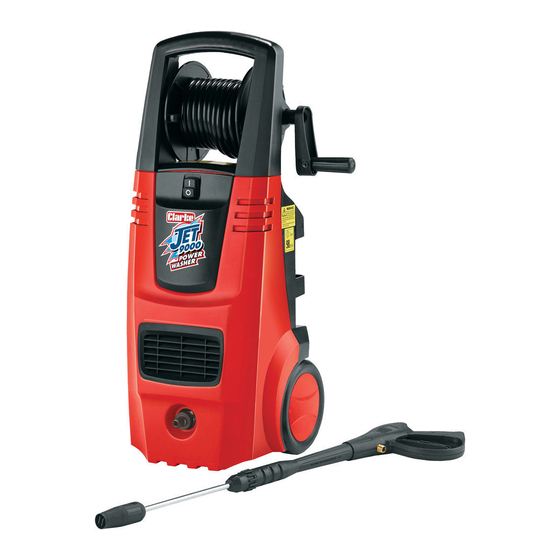
ELECTRICAL CONNECTIONS WARNING: READ THESE ELECTRICAL SAFETY INSTRUCTIONS THOROUGHLY BEFORE CONNECTING THE PRODUCT TO THE MAINS SUPPLY. Before switching the product on, make sure that the voltage of your electricity supply is the same as that indicated on the rating plate. This product is designed to operate on 230VAC 50Hz. - Page 6 OVERVIEW On/OFF Switch Detergent Container Spray Gun Assembly Power Cable Reel Handle Mains Water Inlet Lance Parts & Service: 020 8988 7400 / E-mail: Parts@clarkeinternational.com or Service@clarkeinternational.com...
-
Page 7: Before Use
LIST OF CONTENTS The following items should be supplied in the carton. If any parts are missing or damaged, please see your Clarke dealer where you purchased the machine. 1 x Power Washer 1 x Gun Assembly 1 x Lance c/w fitted Pencil-Jet / Fan - High / Low Nozzle... -
Page 8: Assembling The Lance
• It is recommended to use a reinforced hose with an inner diameter of at least 10 mm available from your CLARKE dealer. • Ensure the water connection is secure. NOTE: The water source must provide a minimum of 6.6 litres per minute... -
Page 9: Filling With Detergent
CLARKE Traffic Film Remover which is a powerful ‘low foaming’ agent for car cleaning, patio cleaning etc., or CLARKE Wash & Wax, both available from your CLARKE dealer. DESCRIPTION SIZE PART NUMBER Car Wash &... -
Page 10: Operation
OPERATION GETTING STARTED 1. Ensure that the water supply is correctly connected and turned on. WARNING: FAILURE TO TURN ON THE WATER FULLY COULD CAUSE DAMAGE TO THE POWER WASHER INTERNAL COMPONENTS. WARNING: DO NOT USE THE POWER WASHER IF THE SUPPLY CABLE OR IMPORTANT PARTS OF THE MACHINE ARE DAMAGED, E.G. -
Page 11: Adjusting The Spray
ADJUSTING THE SPRAY The nozzle is adjustable to allow you to adjust the spray from a narrow jet of water to a wide spray. To adjust the nozzle, proceed as follows: 1. Hold the shaft of the lance in one hand. -
Page 12: Shutting Down
SHUTTING DOWN When you have finished using the power washer, follow the procedure below to switch off and disconnect the unit: 1. Press the stop switch (‘O’). 2. Turn the mains water supply off at the tap. • NEVER turn the water off with the power washer running. -
Page 13: Maintenance
MAINTENANCE WARNING: THE MACHINE SHALL BE DISCONNECTED FROM THE POWER SUPPLY BY REMOVING THE PLUG DURING CLEANING OR MAINTENANCE AND WHEN REPLACING PARTS. CLEANING THE NOZZLE If the nozzle becomes partially clogged with foreign material such as dirt or limescale, excessive pressure may develop and the pump pressure will pulsate. -
Page 14: Storing The Power Washer
Correct use and maintenance is necessary to guarantee the power washer's reliability and best performance. Please only use the correct spare parts as supplied by your Clarke dealer. ANNUALLY LIMESCALE Periodically the pump should be checked for limescale buildup, dependant upon the hardness of the local water supply. -
Page 15: Troubleshooting
PROBLEM POSSIBLE CAUSE SOLUTION No water delivery. Water filter blocked. See cleaning the water filter on page 13. Pump valves jammed. Contact Clarke Service Department. Clogged lance nozzle. Clean the nozzle. Low or irregular Insufficient water supply. Check connections. pressure Pump taking in air. - Page 16 No water due to clogged Clean water inlet filter. inlet filter. Oil leak. Worn seals. Contact your Clarke dealer. Motor does not Plug is not connected Check plug and lead and start when properly. have them replaced by a switched on.
-
Page 17: Product Specifications
PRODUCT SPECIFICATIONS Model Number JET 9000 Part Number 7333502 Voltage 230V/50Hz Motor Input Power 2600 W Duty Cycle Continuous Working pressure 123 bar Maximum pump output pressure 200 bar Maximum output flow rate 7.75 l/min (465 l/hr) Maximum output temperature... - Page 18 PARTS LIST - FRAME & BODY POS DESCRIPTION CODE POS DESCRIPTION CODE Self-tapping Screw TMC9000FB01 Pump Assembly TMC9000FB17 Handle Pin TMC9000FB02 Front Cover TMC9000FB18 Hose Reel TMC9000FB03 Handle TMC9000FB19 Self-tapping Screw TMC9000FB04 Cable Sleeve TMC9000FB20 Cable Hook TMC9000FB05 Switch Holder TMC9000FB21 Cap Screw TMC9000FB06...
-
Page 19: Parts List - Internal Components
PARTS LIST - INTERNAL COMPONENTS Parts & Service: 020 8988 7400 / E-mail: Parts@clarkeinternational.com or Service@clarkeinternational.com... - Page 20 PARTS LIST - INTERNAL COMPONENTS POS DESCRIPTION CODE DESCRIPTION CODE Motor Winding Cover TMC900001 Relief Valve TMC900027 Motor Fan TMC900002 27-1 Sealing Ring TMC9000271 Induction Motor TMC900003 27-2 Relief Valve Piston TMC9000272 Terminal Box TMC900004 27-3 Sealing Ring TMC9000273 Capacitor/wire TMC900005 27-4 Relief Valve Support...
- Page 21 Hex Screw Insert TMC900034 42-2 Main Valve Seat TMC9000422 Pump TMC900035 Hose TMC900043 Spring Washer TMC900036 Nozzle TMC900044 Hex Screw TMC900037 Outlet Connector TMC900045 Hex Screw TMC900038 Hex Screw Insert TMC900046 Sealing Ring TMC900039 Spring TMC900047 One-way Valve TMC900040 Steel Ball TMC900048 40-1 One-way Valve Cover...
-
Page 22: Hose Reel Assembly
HOSE REEL ASSEMBLY No DESCRIPTION CODE No DESCRIPTION CODE Screw TMC9000HOSE01 8 Seal Ring TMC9000HOSE08 Crank Handle TMC9000HOSE02 9 Seal Ring TMC9000HOSE09 Bolt TMC9000HOSE03 10 Hose Spool (L/H) TMC9000HOSE10 Crank Handle TMC9000HOSE04 11 Support Bracket TMC9000HOSE11 Support TMC9000HOSE05 12 HP Hose TMC9000HOSE12 Bracket Connector... -
Page 23: Declaration Of Conformity
DECLARATION OF CONFORMITY Parts & Service: 020 8988 7400 / E-mail: Parts@clarkeinternational.com or Service@clarkeinternational.com...
Need help?
Do you have a question about the JET 9000 and is the answer not in the manual?
Questions and answers