
Subscribe to Our Youtube Channel
Related Manuals for Advantech PCA-6187VE-00A2


Summary of Contents for Advantech PCA-6187VE-00A2
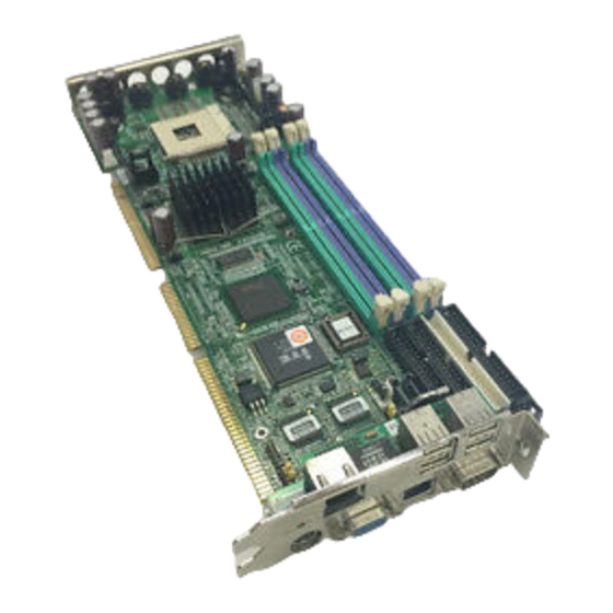
- Page 1 PCA-6187 Full-sized PCI/ISA-bus socket 478 Pentium® 4/Celeron® processor-based CPU card User’s Manual...
-
Page 2: Copyright Notice
Copyright Notice This document is copyrighted, 2004, by Advantech Co., Ltd. All rights are reserved. Advantech Co., Ltd. reserves the right to make improve- ments to the products described in this manual at any time without notice. No part of this manual may be reproduced, copied, translated or transmit- ted in any form or by any means without the prior written permission of Advantech Co., Ltd. - Page 3 Advantech equipment is destined for the laboratory or the factory floor, you can be assured that your product will provide the reliability and ease of operation for which the name Advantech has come to be known. Your satisfaction is our primary concern. Here is a guide to Advantech’s customer services.
- Page 4 PCA-6187 User’s Manual...
-
Page 6: Product Warranty
Advantech assumes no liability under the terms of this warranty as a consequence of such events. If an Advantech product is defective, it will be repaired or replaced at no charge during the warranty period. For out-of-warranty repairs, you will be billed according to the cost of replacement materials, service time and freight. -
Page 7: Initial Inspection
1.0.3 Initial Inspection Before you begin installing your single board computer, please make sure that the following materials have been shipped: 1 PCA-6187 Pentium® 4/Celeron® processor-based single board computer 1 PCA-6187 Startup Manual 1 CD with driver utility and manual (in PDF format) 1 FDD cable P/N: 1700340640 2 Ultra ATA 100 HDD cables... -
Page 8: Important Safety Information
Important Safety Information SAFETY INSTRUCTIONS This device complies with the requirements in part 15 of the FCC rules: Operation is sub- ject to the following two conditions: This device may not cause harmful interference, and This device must accept any interference received, including interference that may cause undesired operation This equipment has been tested and found to comply with the limits for a Class A digital device, pursuant to Part 15 of the FCC Rules. -
Page 9: Table Of Contents
Chapter 1 Hardware Configuration .........2 Introduction ............... 2 Features ................3 Specifications ..............3 1.3.1 System................3 1.3.2 Memory................4 1.3.3 Input/Output..............4 1.3.4 VGA interface..............4 1.3.5 Ethernet LAN..............5 1.3.6 Ultra 160 SCSI..............5 1.3.7 Industrial features ............5 1.3.8 Mechanical and environmental specifications.... - Page 10 Serial Ports (COM1 : CN9; COM2 : CN10 ) ....21 PS/2 Keyboard/Mouse Connector (CN11/CN33) ... 22 2.10 External Keyboard Connector (CN12)......22 2.11 CPU Fan Connector (CN14) ........... 23 2.12 Front Panel Connectors (CN16, 17, 18, 19, 21&29)..23 2.12.1 Power LED (CN16) ............
- Page 11 Advanced Chipset Features..........32 Figure 3.4:Advanced chipset features screen ....33 3.5.1 DRAM Timing Selectable ..........33 3.5.2 CAS Latency Time ............33 3.5.3 Active to Precharge Delay ..........33 3.5.4 DRAM RAS# to CAS# Delay ........33 3.5.5 DRAM RAS# Precharge..........34 3.5.6 Memory Frequency............
- Page 12 Power Management Setup..........40 Figure 3.9:Power management setup screen (1)... 40 3.8.1 Power-Supply Type ............40 3.8.2 ACPI function ............... 40 3.8.3 Video Off Method............40 3.8.4 Video Off In Suspend ..........40 3.8.5 Suspend Type..............40 3.8.6 Modem Use IRQ............40 3.8.7 Soft-Off by PWR-BTTN ..........
- Page 13 Windows XP Driver Setup..........55 Chapter 6 LAN Configuration ........60 Introduction ..............60 Features ................60 Installation............... 61 Win XP Driver Setup (Intel 82547/41/62/51) ....61 Chapter 7 SCSI Setup & Configuration......66 Introduction ..............66 Understanding SCSI............67 SCSI IDs................67 Terminating the SCSI Bus..........
- Page 14 Table B.5:VGA connector (CN7)....... 105 COM1/COM2 RS-232 Serial Port (CN9, CN10)..106 Table B.6:COM1/2 RS-232 serial port (CN9/10)..106 Keyboard and Mouse Connnector (CN11)....106 Table B.7:Keyboard and mouse connector (CN11)..107 External Keyboard Connector (CN12)......107 Table B.8:External keyboard connector (CN12) ..107 CPU Fan Power Connector (CN14) ......
- Page 15 General Information...
-
Page 16: Chapter 1 Hardware Configuration
Chapter 1 Hardware Configuration 1.1 Introduction The PCA-6187 Series all-in-one industrial grade single board computer is a high performance and full-featured computing engine. It follows the PICMG 1.0 specification and meets most requirements for industrial applications. The PCA-6187 uses Intel's 865GV chipset to support Intel's Socket 478 Pentium 4 and Celeron processor with 800/533/400 MHz front side bus. -
Page 17: Features
CPU temperature and system voltages levels are monitored to ensure stable operation. A remote monitoring interface is reserved for remote management through Ethernet by using Advantech's SNMP-1000 system management module. BIOS CMOS backup and restore: When BIOS CMOS setup has been completed, data in the CMOS RAM is automatically backed up to the Flash ROM. -
Page 18: Memory
• SATA/EIDE hard disk drive interface: Supports up to two indepen- dent Serial ATA hard drives (up to 150MB/s) and two IDE hard disk drives or four enhanced IDE devices. Supports PIO mode 4 (16.67 MB/s data transfer rate) and ATA 33/66/100 (33/66/100MB/s data transfer rate.) BIOS enabled/disabled. -
Page 19: Ethernet Lan
1.3.5 Ethernet LAN • Supports single/dual 10/100Base-T networking or single/dual10/100/ 1000Base-T Ethernet networking • Controller: • Single 10/100Base-T: Intel 82562EZ • Single 10/100/1000Base-T: Intel 82547GI (CSA) • Dual 10/100/1000Base-T: Intel 82547GI (CSA) and Intel 82541GI (PCI) 1.3.6 Ultra 160 SCSI •... -
Page 20: Jumpers And Connectors
1.4 Jumpers and Connectors Connectors on the PCA-6187 single board computer link it to external devices such as hard disk drives and a keyboard. In addition, the board has a number of jumpers used to configure your system for your applica- tion. -
Page 21: Table 1.3:Scsi Daughter Board Connectors
Table 1.2: Connectors CN18 Reset connector CN19 HDD LED connector CN20 ATX feature connector CN21 ATX soft power switch (PS_ON) CN22 HW Monitor Alarm Close: Enable OBS Alarm Open: Disable OBS Alarm CN27 Extension I/O board connector CN28 Extension I/O board connector CN29 SM BUS Connector PIN1: SMB_DATA... -
Page 22: Board Layout: Jumper And Connector Locations
1.5 Board Layout: Jumper and Connector Locations Figure 1.1: Jumper and Connector locations PCA-6187 User’s Manual... -
Page 23: Figure 1.2:I/O Connectors
CN 32 CN 9 CN 31 CN 8 CN 7 CN 34 CN 11 Figure 1.2: I/O Connectors 68 Pin for Ultra 160 50 Pin for Ultra wide SCSI Adaptec AIC-7899 68 Pin for Ultra 160 Figure 1.3: SCSI daughter board... -
Page 24: Pca-6187 Block Diagram
1.6 PCA-6187 Block Diagram Processor DDR 266/333/400 Channel A VGA port DDR 266/333/400 Intel 82865GV LAN1 Intel DDR 266/333/400 82547/ Channel B 266MB/s 82562 DDR 266/333/400 LCI Bus PCI to ISA Bridge 2 ATA 100 ITE8888 ports ATA 33/66/100 2 SATA ports Intel 82801EB 150MB/s LAN2 Intel... -
Page 25: Safety Precautions
1.7 Safety Precautions Warning! Always completely disconnect the power cord from your chassis whenever you work with the hardware. Do not make connections while the power is on. Sensitive electronic components can be damaged by sudden power surges. Only experienced electronics personnel should open the PC chassis. -
Page 26: Jumper Settings
1.8 Jumper Settings This section provides instructions on how to configure your single board computer by setting the jumpers. It also includes the single board com- puter's default settings and your options for each jumper. 1.8.1 How to set jumpers You can configure your single board computer to match the needs of your application by setting the jumpers. -
Page 27: Table 1.5:Watchdog Timer Output (J2)
Table 1.5: Watchdog timer output (J2) Function Jumper Setting IRQ11 1-2 closed * Reset 2-3 closed * default setting Note: The interrupt output of the watchdog timer is a low level signal. It will be held low until the watchdog timer is reset. 1.9 System Memory The PCA-6187 has four sockets for 184-pin dual inline memory modules (DIMMs) in two separated memory channels. -
Page 28: Cpu Fsb And Memory Speed
1.9.1 CPU FSB and memory speed The PCA-6187 can accept DDR SDRAM memory chips without parity. Also note: The PCA-6187 accepts PC2100 (DDR266), PC2700 (DDR 333) and PC3200 (DDR 400) DDR SDRAM, depending on the CPU front side bus frequency (FSB). Please refer below table for the relation- ship between the CPU FSB and memory speed. -
Page 29: Memory Installation Procedures
1.10 Memory Installation Procedures To install DIMMs, first make sure the two handles of the DIMM socket are in the "open" position. i.e. The handles lean outward. Slowly slide the DIMM module along the plastic guides on both ends of the socket. Then press the DIMM module right down into the socket, until you hear a click. - Page 30 PCA-6187 User’s Manual...
- Page 31 Connecting Peripherals Chapter 2...
-
Page 32: Chapter 2 Connecting Peripherals
Chapter 2 Connecting Peripherals 2.1 Introduction You can access most of the connectors from the top of the board while it is installed in the chassis. If you have a number of cards installed or have a packed chassis, you may need to partially remove the card to make all the connections. -
Page 33: Floppy Drive Connector (Cn3)
2.3 Floppy Drive Connector (CN3) You can attach up to two floppy disk drives to the PCA-6187's on board controller. You can use 3.5" (720 KB, 1.44 MB) drives. The single board computer comes with a 34-pin daisy-chain drive con- nector cable. -
Page 34: Usb Ports (Cn6)
1 of the cable is red or blue, and the other wires are gray. Make sure that wire 1 corresponds to pin 1 of CN4. Pin 1 is on the upper right side of CN4. 2.5 USB Ports (CN6) The PCA-6187 provides up to six ports of USB (Universal Serial Bus) interface, which gives complete Plug &... -
Page 35: Ethernet Connector (Cn8 And Cn34)
2.7 Ethernet Connector (CN8 and CN34) The PCA-6187 is equipped with single/dual high-performance 32-bit PCI-bus Ethernet interface, which is fully compliant with IEEE 802.3/u 10/100Mbps CSMA/CD and IEEE 802.3ab 1000Base-T standards. It is supported by all major network operating systems and is 100% Novell NE-2000 compatible. -
Page 36: Ps/2 Keyboard/Mouse Connector (Cn11/Cn33)
PS/2 keyboard and a PS/2 mouse, respec- tively. CN11 can also be connected to an adapter cable (P/N: 1700060202, available from Advantech) for connecting to both a PS/2 keyboard and a PS/2 mouse. 2.10 External Keyboard Connector (CN12) -
Page 37: Cpu Fan Connector (Cn14)
2.11 CPU Fan Connector (CN14) CN14 If fan is used, this connector supports cooling fans of 500mA (6W) or less. 2.12 Front Panel Connectors (CN16, 17, 18, 19, 21&29) There are several external switches to monitor and control the PCA-6187 C N 18 C N 21 C N 29... -
Page 38: Reset (Cn18)
2.12.6 SM Bus Connector (CN29) This connector is reserved for Advantech's SNMP-1000 HTTP/SNMP Remote System Manager. The SNMP-1000 allows users to monitor the internal voltages, temperature and fans from a remote computer through an Ethernet network. -
Page 39: Atx Feature Connector (Cn20)
2.13 ATX feature connector (CN20) CN20 Connect to the CN1 on the Advantech backplane to enable the ATX func- tion, 5V stand-by. 2.14 AC-97 Audio interface (CN43) CN43 The PCA-6187 provides AC-97 audio through PCA-AUDIO-00A1 module from Advantech. 2.15 Serial ATA interface (SA0 and SA1) SA0 &... -
Page 40: Connecting To Snmp-1000 Remote Manager
In addition to the two EIDE interfaces (up to four devices), the PCA-6187 features high performance serial ATA interface (up to 150MB/s) which eases cabling to hard drives with thin and long cables. 2.16 Connecting to SNMP-1000 remote manager Use the 6-pin to 8-pin cable to connect the single board computer to SNMP-1000. - Page 41 Award BIOS Setup Chapter 3...
-
Page 42: Chapter 3 Award Bios Setup
Chapter 3 Award BIOS Setup 3.1 Introduction Award’s BIOS ROM has a built-in setup program that allows users to modify the basic system configuration. This type of information is stored in battery-backed memory (CMOS RAM) so that it retains the setup information when the power is turned off. -
Page 43: Entering Setup
3.2 Entering Setup Turn on the computer and press <Del> to allow you to enter the BIOS setup. Figure 3.1: Award BIOS Setup initial screen 3.3 Standard CMOS Setup Choose the “Standard CMOS Features” option from the “Initial Setup Screen” menu, and the screen below will be displayed. This menu allows users to configure system components such as date, time, hard disk drive, floppy drive, display, and memory. -
Page 44: Advanced Bios Features
3.4 Advanced BIOS Features The “Advanced BIOS Features” screen appears when choosing the “Advanced BIOS Features” item from the “Initial Setup Screen” menu. It allows the user to configure the PCA-6187 according to his particular requirements. Below are some major items that are provided in the Advanced BIOS Features screen. -
Page 45: Hyper-Threading Technology
Enabling this feature speeds up memory access. The commands are “Enabled” or “Disabled.” 3.4.5 Hyper-Threading Technology While using CPU with Hyper-Threading technology, you can select "Enabled" to enable Hyper Threading Technology in OS which supports Hyper-Threading Technology or select "Disabled" for other OS which do not support HT technology. -
Page 46: Typematic Delay (Msec)
BIOS accepts the following input values (characters/second) for type- matic rate: 6, 8, 10, 12, 15, 20, 24, 30. 3.4.15 Typematic Delay (msec) Typematic delay is the time interval between the appearance of two con- secutive characters, when holding down a key. The input values for this category are: 250, 500, 750, 1000 (msec). -
Page 47: Figure 3.4:Advanced Chipset Features Screen
screen contains the manufacturer’s default values for the PCA-6187, as shown in Figure 3-4: Note: DRAM default timings have been carefully cho- sen and should ONLY be changed if data is being lost. Please first contact technical sup- port. Figure 3.4: Advanced chipset features screen 3.5.1 DRAM Timing Selectable This item allows you to control the DRAM speed. -
Page 48: Dram Ras# Precharge
In order to improve performance, certain space in memory is reserved for ISA cards. This memory must be mapped into the memory space below 16MB. The Choice: "4", "3" and ''2". 3.5.5 DRAM RAS# Precharge This controls the idle clocks after issuing a precharge command to DRAM. -
Page 49: Integrated Peripherals
3.6 Integrated Peripherals Figure 3.5: Integrated peripherals Figure 3.6: On-Chip IDE Device Chapter 3... -
Page 50: Ide Hdd Block Mode
3.6.1 IDE HDD Block Mode If your IDE hard drive supports block mode select Enabled for automatic detection of the optimal number of block read/writes per sector the drive can support. 3.6.2 On-Chip IDE Device IDE Primary (Secondary) Master/Slave PIO/UDMA Mode (Auto) Each channel (Primary and Secondary) has both a master and a slave, making four IDE devices possible. -
Page 51: Usb Controller
3.6.5 USB Controller Select Enabled if your system contains a Universal Serial Bus (USB) con- troller and you have USB peripherals. The choices: "Enabled", "Dis- abled". 3.6.6 USB 2.0 Controller This entry is for disable/enable USB2.0 controller only. The BIOS itself may/may not have high speed USB support. -
Page 52: Superio Device
3.7 SuperIO Device Figure 3.8: SuperIO Device 3.7.1 Onboard FDC Controller When enabled, this field allows you to connect your floppy disk drives to the onboard floppy disk drive connector instead of a separate controller card. If you want to use a different controller card to connect the floppy disk drives, set this field to Disabled. -
Page 53: Ur2 Duplex Mode
3.7.7 UR2 Duplex Mode This item allows you to select the IR half/full duplex function. The choices: "Half", "Full". 3.7.8 Use IR Pins The Choice : "RxD2, TxD2", "IR-Rx2Tx2". 3.7.9 Onboard Parallel Port This field sets the address of the on-board parallel port connector. You can select either "378/IRQ7", "278/IRQ5", "3BC/IRQ7", or "Disabled". -
Page 54: Power Management Setup
3.8 Power Management Setup The power management setup controls the single board computer's “green” features to save power. The following screen shows the manufac- turer’s defaults. Figure 3.9: Power management setup screen (1) 3.8.1 Power-Supply Type Choose the power-supply type, the choices are "AT" and "ATX". 3.8.2 ACPI function The choice: "Enabled", "Disabled". -
Page 55: Soft-Off By Pwr-Bttn
This determines the IRQ in which the MODEM can use.The choices: "3", "4", "5", "7", "9", "10", "11", "NA". 3.8.7 Soft-Off by PWR-BTTN If you choose “Instant-Off”, then pushing the ATX soft power switch but- ton once will switch the system to “system off” power mode. You can choose “Delay 4 sec.”... -
Page 56: Pnp/Pci Configurations
When Enabled, the system will resume from suspend mode if interrupt occurs. The choice: "Enabled", "Disabled". 3.9 PnP/PCI Configurations Figure 3.10: PnP/PCI configurations screen 3.9.1 Reset Configuration Data Default is Disable. Select Enable to reset Extended System Configuration Data (ESCD) if you have installed a new add-on and system configura- tion has caused such a conflict that OS cannot boot. -
Page 57: Figure 3.11:Pc Health Status Screen
This item will prevent the CPU from overheating. The choices are: "Dis- abled", "50C/122F", "53C/127F", "56C/133F", "60C/140F", "63C/145F", "66C/151F", "70C/158F". Figure 3.11: PC health status screen 3.10.2 Current System Temp This shows you the current temperature of system. 3.10.3 Current CPU Temperature This shows you the current CPU temperature. -
Page 58: Spread Spectrum Control
3.11 Spread Spectrum Control Figure 3.12: Spread Spectrum Control screen 3.11.1 CPU Clock Ratio Key in a DEC number to setup the CPU Clodk Ratio. (Min=8; Max=50). This item only shows up under some special situations. 3.11.2 Spread Spectrum To enable/disable the spread spectrum. The Choice : "Disabled", "- 0.40%", "- 0.50%", "- 0.60%"... -
Page 59: Save & Exit Setup
Please Confirm Your Password Enter the current password and press <Enter>. After pressing <Enter> (ROM password) or the current password (user-defined), you can change the password stored in the CMOS. The password must be no longer than eight (8) characters. Remember, to enable the password setting feature, you must first select either “Setup”... - Page 60 PCA-6187 User’s Manual...
- Page 61 Chipset Software Installation Utility Chapter 4...
-
Page 62: Chapter 4 Chipset Software Install Utility
Chapter 4 Chipset Software Install Utility 4.1 Before you begin To facilitate the installation of the enhanced display device drivers and utility software, you should read the instructions in this chapter carefully before you attempt installation. The device drivers for the PCA-6187 board are located on the software installation CD. -
Page 63: Windows Xp Driver Setup
• Identification of Intel ® chipset components in the Device Manager. • Integrates superior video features. These include filtered sealing of 720 pixel DVD content, and MPEG-2 motion compensation for soft- ware DVD Note: This utility is used for the following versions of Windows system, and it has to be installed before installing all the other drivers: Windows 98SE... - Page 64 Click "Next" when you see the following message. Click "Yes" when you see the following message. PCA-6187 User’s Manual...
- Page 65 Click "Next" when you see the following message. When the following message appears, click "Finish" to complete the installation and restart Windows. Chapter 4...
- Page 66 PCA-6187 User’s Manual...
- Page 67 VGA Setup Chapter 5...
-
Page 68: Chapter 5 Vga Setup
Chapter 5 VGA Setup 5.1 Introduction The PCA-6187 has VGA onboard, you need to install the VGA driver to enable the function. The Intel® 865GV Graphics Memory Controller Hub (the 865GV GMCH) provides an integrated graphics accelerator delivering cost com- petitive 3D, 2D, and video capabilities. -
Page 69: Windows Xp Driver Setup
DVMT dynamically responds to system requirements, and application demands, by allocating the proper amount of display, texturing and buffer memory after the operating system has booted. For example, a 3D appli- cation when launched may require more vertex buffer memory to enhance the complexity of objects, or more texture memory to enhance the richness of the 3D environment. - Page 70 installation procedure is for Windows XP. For other operating systems, please follow the on-screen installation guide Please click on "Next" to continue the installation PCA-6187 User’s Manual...
- Page 71 You will see a welcome window. Please chick on "Next" to con- tinue the installation. Click "Yes" when you see the following message. Chapter 5...
- Page 72 Click on "Yes" to continue the installation Click "Finish" to complete the installation and restart the computer now or later. PCA-6187 User’s Manual...
- Page 73 LAN Configuration Chapter 6...
-
Page 74: Chapter 6 Lan Configuration
Chapter 6 LAN Configuration 6.1 Introduction The PCA-6187 features the 32-bit 10/100/1000 Mbps Ethernet network interface. This interface supports bus mastering architecture and auto- negotiation features. Therefore standard twisted-pair cabling with RJ-45 connectors for 10 Mbps, 100 Mbps and 1000 Mbps connections can be used. -
Page 75: Installation
6.3 Installation Note: Before installing the LAN drivers, make sure the CSI utility has been installed in your system. See Chapter 4 for information on installing the CSI utility. The PCA-6187's onboard Ethernet interface supports all major network operating systems. However, the installation procedure varies with differ- ent operating systems. - Page 76 Select "I accept the terms in the license agreement" and click "Next" to continue. Click "Next" to continue. PCA-6187 User’s Manual...
- Page 77 Click "Install Software" to start the installation procedure. The driver will be installed automatically and the LAN function will be enabled after the installation. Chapter 6...
- Page 78 PCA-6187 User’s Manual...
- Page 79 SCSI Setup & Configuration Chapter 7...
-
Page 80: Chapter 7 Scsi Setup & Configuration
Chapter 7 SCSI Setup & Configuration 7.1 Introduction The PCA-6187 is equipped with an Adaptec AIC-7899 single-chip PCI- to-SCSI host adapter which provides a dual channel Ultra 160 multi- tasking interface between your computer.s PCI bus and SCSI devices (disk drives, CD-ROM drives, scanners, tape backups, removable media drives, etc.). -
Page 81: Understanding Scsi
7.2 Understanding SCSI SCSI (pronounced .scuzzy.) stands for Small Computer Systems Inter- face. SCSI is an industry standard computer interface for connecting SCSI devices to a common SCSI bus. A SCSI bus is an electrical pathway that consists of a SCSI interface installed in a computer and one or more SCSI devices. -
Page 82: Terminating The Scsi Bus
• If you are booting your computer from a SCSI hard disk drive con- nected to the SCSI bus, the Boot SCSI ID setting in the SCSISelect utility must correspond to the SCSI ID of the device from which you are booting. -
Page 83: Configuring The Scsi Interface With Scsiselect
7.5 Configuring the SCSI interface with SCSISelect SCSISelect, included with the CPU card, enables you to change SCSI set- tings without opening the computer. SCSISelect also enables you to low- level format or verify the disk media of your SCSI hard disk drives. The following table lists the available and default settings for each SCSISelect option. - Page 84 Sync Transfer Rate (MBytes/sec) 160, 80.0, 53.4, 40.0, 32.0, 26.8, 20.0, 16.0, 13.4, 10.0 ASYN Initiate Wide Yes, No Yes (enabled) Negotiation Enable Yes, No Yes (enabled) Disconnection Send Start Unit Yes, No Yes (enabled) Command Enable Write Back N/C (No Change) N/C (No Change) Cache2 Yes, No...
-
Page 85: Starting Scsiselect
BIOS Support for Enabled, Disabled Enabled Int 13 Extensions2 1 Setting is valid only if Multiple LUN Support is enabled. 2 Settings are valid only if host adapter BIOS is enabled. 7.6 Starting SCSISelect Follow these steps to start SCSISelect: Turn on or restart your system. - Page 86 SCSI Bus Interface Definitions • Host Adapter SCSI ID-(Default: 7) Sets the SCSI ID for the SCSI controller. The Adaptec SCSI controller AIC-7899 is set at 7, which gives the highest priority on the SCSI bus. We recommend that you do not change this setting.
- Page 87 Note: Set Initiate Wide Negotiation to NO if you are using an 8-bit SCSI device that hangs or exhib- its other performance problems with 16-bit data transfer rate enabled. • Enable Disconnection-(Default: Yes) When set to Yes, allows the SCSI device to disconnect from the SCSI bus. Leave the setting at Yes if two or more SCSI device is connected, changing the setting to No results in slightly better performance.
- Page 88 SCSISelect Utility by pressing <Ctrl> <A> after the SCSI card BIOS banner appears. • Extended BIOS Translation for DOS Drives > 1 GByte-(Default: Enabled) When set to Enabled, provides an extended translation scheme for SCSI hard disks with capacities greater than 1 GByte. This setting is necessary only for MS-DOS 5.0 or above;...
-
Page 89: Using Scsi Disk Utilities
• Disabled. No removable-media drives are treated as hard disk drives. Software drivers are required because the drives are not controlled by the BIOS. • Boot Only.Only the removable-media drive designated as the boot device is treated as a hard disk drive. •... -
Page 90: Installation Under Windows 2000
7.8 Installation under Windows 2000 If you are only using SCSI hard drives without any IDE HDD drive installed. Please follow these steps: Insert Windows 2000 CD Disk. Press F6 immediately when it displays: “Set up is inspecting your computer’s hardware configuration.” Then it enter SCSI installation. - Page 91 In the “System properties”, choose “PCI SCSI Bus Controller.” Then click on “Properties.” Click on "Update Driver" Chapter 7...
- Page 92 Click on “Next” Recommend to search for a better driver PCA-6187 User’s Manual...
- Page 93 If the SCSI driver is supplied in floppy disk, click on “Floppy disk drives.” Then, click on “Next.” If the SCSI driver is supplied in CD-ROM disk, click on “Specify a location:" then enter "E:\Drv_SCSI\AIC7899\Windows\Win9X" In the "Update Device Driver Wizard" click on "Next." Chapter 7...
- Page 94 The installation is completed. Click on "Finish." Click on "Yes" to restart the system. PCA-6187 User’s Manual...
- Page 95 USB 2.0 Configuration Chapter 8...
-
Page 96: Chapter 8 Usb 2.0 Configuration
Chapter 8 USB 2.0 Configuration 8.1 Introduction The PCA-6187 is designed with Intel ICH5 which supports both USB1.1 and USB 2.0 high-speed transmission. It still remains the compatibility with today's USB device. High-speed USB 2.0 provides data transfer up to 480Mb/s which is 40 times faster than USB 1.1. It is ideal for today's speed-demanding I/O peripherals. - Page 97 Onboard Security Setup Chapter 9...
-
Page 98: Chapter 9 Onboard Security Setup
Chapter 9 Onboard Security Setup 9.1 Introduction The PCA-6187's hardware monitor is designed with Winbond W83627HF. Onboard security (OBS) functions monitor key hardware. They help you maintain your system's stability and durability. The PCA-6187 can monitor 5 sets of system positive voltages, 2 sets of system negative voltages, CPU cooling fan speed, and CPU temperature. -
Page 99: Windows Xp Driver Setup
9.2 Windows XP Driver Setup Insert the driver CD into your system's CD-ROM drive. In a few seconds, the software installation main menu appears, as shown in the following figure. Click on the "Install" button under the "OBS DRIVERS" heading. Click "Next"... - Page 100 Click "Next" when you see the following message. Click "Next" when you see the following message. PCA-6187 User’s Manual...
- Page 101 Click "Next" to continue. Click "Finish" when you see the following message. Chapter 9...
-
Page 102: Using The Obs Hardware Doctor Utility
9.3 Using the OBS Hardware Doctor Utility After completing the setup, all the OBS functions are permanently enabled. When a monitored reading exceeds safe limits, a warning mes- sage will be displayed and an error beep tone will activate to attract your attention. - Page 103 Chapter 9...
- Page 104 PCA-6187 User’s Manual...
- Page 105 Programming the Watchdog Timer Appendix A...
-
Page 106: Appendix A Programming The Watchdog
Appendix A Programming the watchdog A.1 Programming the Watchdog Timer The PCA-6187's watchdog timer can be used to monitor system software operation and take corrective action if the software fails to function after the programmed period. This section describes the operation of the watchdog timer and how to program it. - Page 107 Unlock W83627H Select register of watchdog timer Enable the function of the watchdog timer Use the function of the watchdog time Lock W83627HF Appendix A...
- Page 108 Watchdog Timer Registers Address of register (2E) Attribute Read/Write Value (2F) and description 87 (hex) ----- Write this address to I/O address port 2E (hex) twice to unlock theW83627HF 07 (hex) write Write 08 (hex) to select reg- ister of watchdog timer. 30 (hex) write Write 01 (hex) to enable...
-
Page 109: Example Program
F7 (hex) read/write Bit 6: Write 1 to enable key- board to reset the timer, 0 to disable.[default] Bit 5: Write 1 to generate a timeout signal immediately and automatically return to 0. [default=0] Bit 4: Read status of watch- dog timer, 1 means timer is ""time out""."... - Page 110 ;----------------------------------------------------------- Dec dx ; Set second as counting unit Mov al,0f5h Out dx,al al,dx And al,not 08h Out dx,al ;----------------------------------------------------------- Dec dx ; Set timeout interval as 10 seconds and start counting Mov al,0f6h Out dx,al Mov al,10 Out dx,al ;----------------------------------------------------------- Dec dx ;...
- Page 111 ;----------------------------------------------------------- Dec dx ; Enable the function of watchdog timer Mov al,30h Out dx,al Mov al,01h Out dx,al ;----------------------------------------------------------- Dec dx ; Set minute as counting unit Mov al,0f5h Out dx,al al,dx Or al,08h Out dx,al ;----------------------------------------------------------- Dec dx ; Set timeout interval as 5 minutes and start counting Mov al,0f6h Out dx,al Mov al,5...
- Page 112 Out dx,al ;----------------------------------------------------------- Mov al,07h ; Select registers of watchdog timer Out dx,al Mov al,08h Out dx,al ;----------------------------------------------------------- Dec dx ; Enable the function of watchdog timer Mov al,30h Out dx,al Mov al,01h Out dx,al ;----------------------------------------------------------- Dec dx ; Enable watchdog timer to be reset by mouse Mov al,0f7h Out dx,al al,dx...
- Page 113 Out dx,al ;----------------------------------------------------------- Mov al,07h ; Select registers of watchdog timer Out dx,al Mov al,08h Out dx,al ;----------------------------------------------------------- Dec dx ; Enable the function of watchdog timer Mov al,30h Out dx,al Mov al,01h Out dx,al ;----------------------------------------------------------- Dec dx ; Enable watchdog timer to be strobed reset by keyboard Mov al,0f7h Out dx,al al,dx...
- Page 114 Out dx,al ;----------------------------------------------------------- Mov al,07h ; Select registers of watchdog timer Out dx,al Mov al,08h Out dx,al ;----------------------------------------------------------- Dec dx ; Enable the function of watchdog timer Mov al,30h Out dx,al Mov al,01h Out dx,al ;----------------------------------------------------------- Dec dx ; Generate a time-out signal Mov al,0f7h Out dx,al ;Write 1 to bit 5 of F7 register...
- Page 115 I/O Pin Assignments Appendix B...
-
Page 116: Appendix B Pin Assignments
Appendix B Pin Assignments B.1 IDE Hard Drive Connector (CN1, CN2) Table B.1: IDE hard drive connector (CN1, CN2) Signal Signal IDE RESET* DATA 7 DATA 8 DATA 6 DATA 9 DATA 5 DATA 10 DATA 4 DATA 11 DATA 3 DATA 12 DATA 2 DATA 13... -
Page 117: Floppy Drive Connector (Cn3)
B.2 Floppy Drive Connector (CN3) Table B.2: Floppy drive connector (CN3) Signal Signal FDHDIN* FDEDIN* INDEX* MOTOR 0* DRIVE SELECT 1* DRIVE SELECT 0* MOTOR 1* DIRECTION* STEP* WRITE DATA* WRITE GATE* TRACK 0* WRITE PROTECT* READ DATA* HEAD SELECT* DISK CHANGE* * low active Appendix B... -
Page 118: Parallel Port Connector (Cn4)
B.3 Parallel Port Connector (CN4) Table B.3: Parallel port connector (CN4) Signal Signal STROBE* AUTOFD* INIT* SLCTINI* ACK* BUSY SLCT * low active PCA-6187 User’s Manual... -
Page 119: Usb Connector (Cn6)
B.4 USB Connector (CN6) Table B.4: USB1/USB2 connector (CN6) USB1 Signal USB2 Signal +5 V +5 V Chassis GND N/CA B.5 VGA Connector (CN7) Table B.5: VGA connector (CN7) Signal Signal GREEN BLUE H-SYNC V-SYNC Appendix B... -
Page 120: Com1/Com2 Rs-232 Serial Port (Cn9, Cn10)
B.6 COM1/COM2 RS-232 Serial Port (CN9, CN10) Table B.6: COM1/2 RS-232 serial port (CN9/10) Signal B.7 Keyboard and Mouse Connnector (CN11) PCA-6187 User’s Manual... -
Page 121: Table B.7:Keyboard And Mouse Connector (Cn11)
Table B.7: Keyboard and mouse connector (CN11) Signal KB DATA MS DATA KB CLOCK MS CLOCK B.8 External Keyboard Connector (CN12) Table B.8: External keyboard connector (CN12) Signal DATA Appendix B... -
Page 122: Cpu Fan Power Connector (Cn14)
B.9 CPU Fan Power Connector (CN14) Table B.9: CPU Fan Power Connector (CN14) Signal +12V Detect B.10 Power LED (CN16) You can use an LED to indicate when the single board computer is on. Pin 1 of CN16 supplies the LED's power, and Pin 3 is the ground. Table B.10: Power LED and keylock conn (CN16) Function LED power (+5 V) -
Page 123: External Speaker Connector (Cn17)
B.11 External Speaker Connector (CN17) The single board computer has its own buzzer. You can also connect it to the external speaker on your computer chassis. Table B.11: External Speaker Connector (CN17) Function Internal buzzer Internal buzzer Speaker out B.12 Reset Connector (CN18) Table B.12: Reset connector (CN18) Signal RESET... -
Page 124: Hdd Led Connector (Cn19)
B.13 HDD LED Connector (CN19) Table B.13: HDD LED connector (CN19) Signal VCC (LED+) IDE LED (LED-) B.14 ATX Feature Connector (CN20) Table B.14: ATX feature connector (CN20) Signal PS-ON VCCSB PCA-6187 User’s Manual... -
Page 125: Atx Soft Power Switch (Cn21))
B.15 ATX Soft Power Switch (CN21)) Table B.15: ATX soft power switch (CN21) Signal 5VSB PWR-BTN B.16 H/W Monitor Alarm (CN22) Table B.16: H/W monitor alarm (CN22) Signal Enable OBS alarm Disable OBS alarm B.17 AC-97 Audio Interface (CN43) Appendix B... -
Page 126: Sm Bus Connector (Cn29)
Table B.17: AC-97 Audio Interface (CN43) 1 VCC 2 GND 3 SYNC 4 BITCLK 5 SDOUT 6 SDIN0 7 SDIN1 8 AC-RST 9 +12V 10 GND 11 GND 12 N/C B.18 SM Bus Connector (CN29) Table B.18: SM Bus Connector (CN 29) Signal SMB_DATA SMB_CLK... -
Page 127: System I/O Ports
B.19 System I/O Ports Table B.19: System I/O ports Addr. range (Hex) Device 000-01F DMA controller 020-021 Interrupt controller 1, master 022-023 Chipset address 040-05F 8254 timer 060-06F 8042 (keyboard controller) 070-07F Real-time clock, non-maskable interrupt (NMI) mask 080-09F DMA page register 0A0-0BF Interrupt controller 2 0C0-0DF... -
Page 128: Dma Channel Assignments
B.20 DMA Channel Assignments Table B.20: DMA channel assignments Channel Function Available Available Floppy disk (8-bit transfer) Available Cascade for DMA controller 1 Available Available Available B.21 Interrupt Assignments Table B.21: Interrupt assignments Priority Interrupt# Interrupt source Parity error detected IRQ0 Interval timer IRQ1... -
Page 129: 1St Mb Memory Map
B.22 1st MB Memory Map Table B.22: 1st MB memory map Addr. range (Hex) Device E0000h - FFFFFh BIOS CC000h - DFFFFh Unused C0000h - CBFFFh VGA BIOS A0000h - BFFFFh Video Memory 00000h - 9FFFFh Base memory B.23 PCI Bus Map Table B.23: PCI bus map Function Signals Device ID... - Page 130 PCA-6187 User’s Manual...
Need help?
Do you have a question about the PCA-6187VE-00A2 and is the answer not in the manual?
Questions and answers