FLIR DNR100 SERIES Instruction Manual
Hide thumbs
Also See for DNR100 SERIES:
- Instruction manual (172 pages) ,
- Quick networking manual (2 pages)
Table of Contents
Advertisement
Quick Links
Advertisement
Table of Contents
Troubleshooting

Related Manuals for FLIR DNR100 SERIES


Summary of Contents for FLIR DNR100 SERIES
- Page 1 Instruction Manual DNR100 SERIES...
- Page 3 Instruction Manual DNR100 SERIES #; r. 1.0/12560/12560; en-US...
- Page 4 Thank you for purchasing this product. FLIR is committed to providing our customers with a high quality, reliable security solution. This manual refers to the following models: DNR100 Series For the latest online manual, downloads and product updates, and to learn about our complete line of accessory products, please visit our website at: www.flirsecurity.com/pro...
-
Page 5: Table Of Contents
General Precautions..............1 Installation................. 1 Service ..................3 Use..................3 DNR100 Series Features...............4 DNR100 Series Getting Started .............5 DNR100 Series Basic Setup ..............6 DNR100 Series Front Panel..............8 DNR100 Series Rear Panel..............9 Mouse Control .................. 10 Using the System ................11 On-Screen Display .............. - Page 6 13.4.12 Deleting Groups............. 49 13.4.13 Modifying Groups............49 13.4.14 Auto Maintain ..............50 13.4.15 Config Backup............... 50 13.5 Shutdown................52 FLIR SyncroIP NVR CMS Central Management Software......53 14.1 System Requirements..............53 14.2 Prerequisites ................53 14.3 Installing FLIR SyncroIP NVR CMS..........53 14.4...
- Page 7 Table of contents 14.11 Adding User Accounts to the CMS..........69 14.12 Multi-Monitor Support ..............69 14.12.1 Opening Cameras in Secondary Monitors......70 14.12.2 Managing Secondary Monitors.......... 70 Remote Viewing On Internet Explorer ..........72 15.1 Prerequisites ................72 15.1.1 IE Live Display Overview..........73 15.1.2 Using Search Mode in IE (Playback)........
- Page 8 Remote Firmware Upgrade ............... 114 20.1 Installing a Firmware Upgrade Over the LAN......... 114 20.2 Installing a Firmware Upgrade Over the Internet......115 DNR100 Series Hard Drive Installation ..........117 21.1 Installing a Hard Drive.............. 117 21.2 Removing the Hard Drive............119 21.3...
-
Page 9: Important Safeguards
Important Safeguards In addition to the careful attention devoted to quality standards in the manufacturing proc- ess of your product, safety is a major factor in the design of every instrument. However, safety is your responsibility too. This sheet lists important information that will help to en- sure your enjoyment and proper use of the product and accessory equipment. - Page 10 Important Safeguards 5. Power Sources - This product should be operated only from the type of power source indicated on the marking label. If you are not sure of the type of power supplied to your location, consult your video dealer or local power company. For products intended to operate from battery power, or other sources, refer to the operating instructions.
-
Page 11: Service
Important Safeguards 17. Camera Installation - Cameras are not intended for submersion in water. Not all cam- eras can be installed outdoors. Check your camera environmental rating to confirm if they can be installed outdoors. When installing cameras outdoors, installation in a sheltered area is required. -
Page 12: Dnr100 Series Features
• Advanced mobile app features: remote playback, push notifications for motion/alarm, E-map, manual record/snapshot to device. • HDMI & VGA simultaneous video output. • Free DDNS service by FLIR with secure and redundant servers. • Supports 1x SATA HDD up to 3TB. • 2 x USB 2.0 ports. -
Page 13: Dnr100 Series Getting Started
DNR100 Series Getting Started The system comes with the following components: Power adapter x 2 Network Video Recorder Mouse (1 x for PoE switch, 1 x for NVR) Quick start guides & software Ethernet cable Hard drive size, number of channels, and camera configuration may vary by model. Please refer to your package for specific content details. -
Page 14: Dnr100 Series Basic Setup
DNR100 Series Basic Setup 1. Connect the Cameras • Connect IP cameras to PoE (Power over Ethernet) Ports. • Connect IP cameras to the same LAN as the NVR. For details on connecting IP cameras over the LAN, see 13.3 Device Search, page 40. - Page 15 DNR100 Series Basic Setup 5. Connect the Power Adapters 5.1. Connect the DC 48V power adapter to the DC 48V port on the rear panel of the system. Connect the power cable to an outlet, power strip, or surge protector.
-
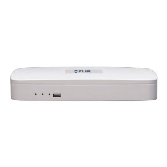
Page 16: Dnr100 Series Front Panel
DNR100 Series Front Panel 1. NET: Glows when network is in normal state. Turns off for network error. 2. Power Indicator: Glows to indicate the system is on. 3. HDD: Glows to indicate hard drive is in normal state. Turns off when there is a hard drive error. -
Page 17: Dnr100 Series Rear Panel
DNR100 Series Rear Panel 1. DC 48V: Port for 48V DC power adapter (included) that supplies power to the cameras connected to the integrated PoE ports. 2. DC 12V: Port for 12V DC power adapter (included) that supplies power to the NVR. -
Page 18: Mouse Control
Mouse Control The mouse is the primary control device for the system. To connect a USB mouse: Connect a USB mouse to the USB port on the front or rear panel. 1. Left-Button: • In live view, click to open the Navigation Bar. •... -
Page 19: Using The System
Using the System Note The default system user name is admin and password is 000000. 8.1 On-Screen Display The system shows the following for all display views: 1. Display Area: • Double-click on a channel to view in full-screen; double-click again to return to split screen. -
Page 20: Adjusting Color Settings
Using the System The Quick Menu has the following options: • View: Select a camera in full-screen or select a multi-channel display. • Pan/Tilt/Zoom: Access controls for PTZ cameras (not included). • AutoFocus: If your camera has a mechanical focus lens, click to configure the zoom/fo- cus levels or activate auto focus. -
Page 21: Using The Navigation Bar
Using the System 3. Click OK to save changes. 8.4 Using the Navigation Bar The Navigation Bar gives quick access to certain functions and menus. To open the Navigation bar: • Left click on the screen to open the Navigation Bar. The Navigation Bar has the follow- ing options: 4 5 6 7 8 9 Main Menu. -
Page 22: Using Digital Zoom In Live Display
Using the System 2. Right-click to exit Quick Playback. 8.5.2 Using Digital Zoom in Live Display 1. Move your mouse to the top of the channel display and click to activate digital zoom. The icon will change to , indicating digital zoom is activated. Note You may activate digital zoom in multiple channels at the same time. -
Page 23: Adjusting Camera Zoom & Focus
Using the System 8.7 Adjusting Camera Zoom & Focus If your camera has a motorized lens, you can control the zoom/focus level or activate auto focus from the NVR. To adjust the camera’s zoom focus: 1. Double-click on the channel where the motorized lens camera is connected. 2. -
Page 24: Setting The Time
Setting The Time CAUTION It is highly recommended to set the time on the system prior to doing any recording. To set the date and time: 1. In the main viewing mode, right-click and click Main Menu. Log into the system using the admin account (default user name is admin and password is 000000). -
Page 25: Recording
Recording By default, the system is set to immediately record at startup from connected cameras. This is called Continuous Recording. It is highly recommended to keep Continuous Re- cording on at all times. The system supports the following recording types: •... -
Page 26: Search (Playback)
Search (Playback) Search mode is used to navigate and playback recorded video files on the NVR. 11.1 Playing Back Video from the Hard Drive 1. From live view, right-click and then click Search. If needed, log in using the admin ac- count (default user name is admin and default password is 000000). -
Page 27: Playback Controls
Search (Playback) 11.2 Playback Controls Select playback device. Calendar: Select the day to playback. Channel select: Select channels to playback. Video clip backup: Select video clip start and end times. Backup video clip: Click to save selected clip. Playback Bar: Click inside the bar to select a playback time. Zoom Playback Bar: Select scope of time bar. -
Page 28: Backup
Backup Backup video files to external USB flash drive (not included) or self-powered USB external hard drive (not included). 12.1 Formatting the USB Device It is recommended to format your USB device before using it with the system. CAUTION Formatting the USB device will permanently erase all data. To format a USB device: 1. - Page 29 VLC Media Player is a free software available from www.videolan.org. VLC Media Player is not supported by FLIR. • Start Time/End Time: Select the start and end time for your search. 7. Click Add. A list of files that match your search criteria appears.
-
Page 30: Using Video Clip Backup
ASF under File Format). You can playback .asf backup video files in VLC Media Player (free download from www.videolan.org) on PC or Mac. VLC Media Player is not supported by FLIR. To view backup video files using the Player (PC only): 1. Insert the USB device into your computer. Open the USB device in Windows Explorer. - Page 31 Backup Video Player Controls 10 11 12 Select playback time. Open files. Play/pause. Stop/Stop recording. Start recording. Previous file. Slow. Back one frame. Forward one frame. 10. Fast. 11. Next file. 12. Snapshot. 13. Shuffle/repeat. 14. Full-screen. #; r. 1.0/12560/12560; en-US...
- Page 32 Backup Note To view or change where manual recordings or snapshots are saved, right click in the video area and se- lect Parameter Setting. #; r. 1.0/12560/12560; en-US...
-
Page 33: Using The Main Menu
Using the Main Menu To open the Main Menu: • Using the Mouse: Right-click and click Main Menu. Note The system password may be required to access the Main Menu. By default the user name is admin and the password is 000000. 1. -
Page 34: Info
Using the Main Menu 13.1 Info The Info menu contains the following sub-menus showing system information. 13.1.1 HDD Info The HDD Info sub-menu shows information related to the hard drives installed in the sys- tem, including capacity, status, and type. Click View recording time to see the start and end times of recordings saved on the hard drives. -
Page 35: Version (Updating Firmware)
Using the Main Menu To search for system logs: 1. Under Type, select the log type to search for. 2. Under Start Time and End Time, select the start and end time for your search. 3. Click Search. 4. (Optional) Click Backup to export logs to a USB flash drive connected to the system. 13.1.4 Version (Updating Firmware) The Version sub-menu allows you to view information about the current firmware. -
Page 36: Remote Device Info
Using the Main Menu The Online Users sub-menu shows a list of users connected to the system using remote devices. You may click Disconnect to disconnect a user for up to 18 hours or click Block to block a user from the system. 13.1.6 Remote Device Info The Remote Device Info sub-menu shows information about IP cameras connected to the system, it contains the following tabs:... -
Page 37: Setting
Using the Main Menu 13.2 Setting The Setting menu allows you to configure general system, schedule, network, recording, display, and motion settings. It also allows you to restore the system to factory defaults. 13.2.1 General The General sub-menu allows you to configure the time and general system settings. The General sub-menu contains the following options: •... -
Page 38: Recording
Using the Main Menu 13.2.2 Recording The Recording sub-menu allows you to configure image quality settings for the recording stream and sub-stream (used during remote connection). Settings for the recording stream are shown on the left, and sub-stream settings are shown on the right. To configure recording quality settings: 1. -
Page 39: Configuring Pre-Recording
Using the Main Menu The Schedule sub-menu allows you to configure the recording schedule for continuous and motion recording. It also allows you to configure holiday and pre-recording settings. Note To use motion recording, motion detection must be enabled for the channel. For details, see 13.2.14 Mo- tion, page 36. -
Page 40: Network
Using the Main Menu 13.2.6 Network The Network sub-menu allows you to configure network settings. 13.2.7 Configuring DHCP or Fixed IP Address 1. From live view, right-click and select Main Menu. Login if prompted. 2. Click Setting>Network. 3. Check DHCP to use DHCP or un-check to use a static IP address. If you un-check DHCP, configure the following: •... -
Page 41: Configuring Ntp
6. Click OK. Click Save to save your changes. 13.2.10 Configuring DDNS The DDNS Setup window allows you to enter your FLIR DDNS settings in the NVR. This step is required for remote access. Prerequisites: • Create a DDNS account. For details, “Appendix D: Setting Up DDNS Service” on page 98. -
Page 42: Connecting To Your System
The DDNS URL must include http:// , the name of your DDNS URL, followed by a colon, then the HTTP port of your NVR. For example: http://tomsmith.myddns-flir.com:80 Note If you change your HTTP port number (port 80) to a different port, you must enter your port number after the DDNS address 13.2.12 Configuring Email Alerts... - Page 43 Using the Main Menu 4. Check Email. Double-click Email. 5. Configure the following: • SMTP Server: Enter the SMTP server address. • Port: Enter the port used by the SMTP server. • Anonymous: Check if your server supports anonymous log ins. Otherwise, leave this unchecked.
-
Page 44: Configuring Switch Settings
Using the Main Menu 13.2.13 Configuring Switch Settings You can configure the networking settings for the internal PoE switch. CAUTION Changing this information from the default values may disrupt the connection to the cameras. Make sure your IP cameras are using DHCP or IP addresses that are compatible with your selected settings. To configure switch settings: 1. - Page 45 Using the Main Menu 4. Click Select next to Region to configure which areas of the image will be enabled for motion detection. A grid will appear over the camera’s live view. Motion Grid Areas enabled for motion detection are shown in red and areas that are disabled are transparent. Click and drag to enable or disable areas for motion detection.
-
Page 46: Display
Using the Main Menu 13.2.16 Display The Display sub-menu allows you to configure the system’s display settings, such as the monitor resolution. To configure display settings: 1. Configure the following, as needed: • Transparency: Select the menu transparency between 128 (lowest) and 255 (highest). -
Page 47: Default
Using the Main Menu 13.2.17 Default The Default sub-menu allows you to reset the system to factory default settings. Note Resetting to factory defaults does not reset user accounts or passwords. To reset the system to factory default settings: 1. Check the menus you would like to reset to default settings. 2. -
Page 48: Device Search
Using the Main Menu 13.3 Device Search The Device Search menu allows you to manage connections to your IP cameras. SyncroIP cameras connected to the PoE (Power over Ethernet) Ports will automatically be detected by your NVR. Device Search also allows you to search for IP cameras connected to the LAN. -
Page 49: Manual Add
Using the Main Menu 6. If the Status indicator is red, click . Update the following information, as needed. • Manufacturer: Select the manufacturer of your IP camera. • User: Enter the camera’s user name. • Password: Enter the camera’s password. •... -
Page 50: Editing Cameras
Using the Main Menu To manually add a camera to the NVR: 1. Click Manual Add. Configure the following: • IP Address: Enter the IP address of your IP camera. • Manufacturer: Select the manufacturer of your IP camera. • User: Enter the camera’s user name. •... -
Page 51: Advanced
Using the Main Menu 13.4 Advanced Configure HDD, user accounts, and error functions. Configure auto-restart. Save/restore system configuration. Access Recording Menu. 13.4.1 HDD Management HDD Management allows you to format hard drives and manage hard drive settings. The top right corner shows hard drive status. •... -
Page 52: Selecting Hard Drive Types
Using the Main Menu 2. Configure the following: 2.1. Under HDD No., select the hard drive you would like to format. Information about the hard drive appears in the lower section of the menu. 2.2. Under Set to, select Format. 2.3. -
Page 53: Warning
Using the Main Menu 2. Under HDD Group select the group number you would like to assign to each hard drive. 3. Click OK. The system will restart. 4. Return to the HDD Manage menu (right-click>Main Menu>Advanced>HDD Manage). Click HDD Channel. 5. -
Page 54: Record
Using the Main Menu To configure system error actions: 1. Under Event Type, select one of the following system errors to configure: No Disk, Disk Error, Disk No Space, Net Disconnection, IP Conflicted, or MAC Conflicted. 2. Check Enable to enable warnings for the selected Event Type. 3. -
Page 55: Account
Using the Main Menu 13.4.7 Account The Account sub-menu allows you to configure user accounts. Accounts are organized in- to groups, and receive permission to access system functions based on their group’s set- tings. By default, the following user groups are configured on the system: •... -
Page 56: Modifying Accounts
Using the Main Menu 3. In the bottom portion of the screen, select the permissions that will apply to the user. By default the account will have all permissions that are enabled for its group. An ac- count cannot have more permissions than its group. 4. -
Page 57: Adding Groups
Using the Main Menu 2. Click Modify User. 3. Under User, select the account you would like to delete. 4. Click Delete then click OK to confirm. 13.4.11 Adding Groups Groups allow you to easily manage permissions for multiple user accounts. A user account by default has all permissions available to the group it is in, and it cannot be given permis- sions the group does not have. -
Page 58: Auto Maintain
Using the Main Menu 3. Update group settings as needed and then click Save. 13.4.14 Auto Maintain The Auto-Maintain sub-menu allows you to configure your system to automatically reboot once a day or once a week. For system stability, it is recommended to enable auto- rebooting. - Page 59 Using the Main Menu To export the system configuration to a USB flash drive: 1. Insert a USB flash drive into one of the USB ports on the system. 2. Right-click and select Main Menu>Advanced>Config Backup. 3. Check the USB flash drive you would like to export to in the list. 4.
-
Page 60: Shutdown
Using the Main Menu 13.5 Shutdown Use the Shutdown menu to shutdown, restart, or log out of the system. To access the Shutdown menu: 1. From live view, right-click and select Main Menu. Login if prompted. 2. Click Shutdown. 3. Select one of the following: •... -
Page 61: Flir Syncroip Nvr Cms Central Management Software
FLIR SyncroIP NVR CMS Central Management Software FLIR SyncroIP NVR CMS is a central management software that allows you to view and manage multiple NVRs and IP cameras. 14.1 System Requirements Your system must meet or exceed the system requirements below:... -
Page 62: Adding A Nvr Or Ip Camera From The Local Area Network (Lan)
FLIR SyncroIP NVR CMS Central Management Software Note The CMS default User Name is admin and the Password is admin. 14.4 Adding a NVR or IP Camera from the Local Area Network (LAN) Once you open the software, you can add a NVR or IP camera. -
Page 63: Adding A Nvr Or Ip Camera Using A Ddns Address
FLIR SyncroIP NVR CMS Central Management Software 4. Enter the system’s user name and password (default user name for this system is ad- minand default password is 000000) and click OK. 5. Click OK. 6. Click Device List. 7. Perform the following steps to open the NVR or IP camera: 7.1. - Page 64 FLIR SyncroIP NVR CMS Central Management Software To add a system using a DDNS address: 1. Click Config Manager>Device Manage. 2. Click Manual Add. #; r. 1.0/12560/12560; en-US...
- Page 65 FLIR SyncroIP NVR CMS Central Management Software 3. Configure the following: 3.1. Title: Enter a name for your system of your choice (e.g. home or office). 3.2. Type: Select NVR for NVRs or IP Camera for IP cameras. 3.3. Add Type: Select Domain Name for NVRs or Single Device for IP cameras.
-
Page 66: Cms Live Viewing Overview
FLIR SyncroIP NVR CMS Central Management Software 14.5.1 CMS Live Viewing Overview 1. Camera Controls: 1.1. Digital zoom: Click and drag to zoom. 1.2. Change display mode. 1.3. Manual record. 1.4. Snapshot. 1.5. Mute. 1.6. Disconnect. 2. Live View Toolbar: 2.1. -
Page 67: Using Alarm Rec (Event Search)
FLIR SyncroIP NVR CMS Central Management Software 4. CMS Window Controls: 4.1. Lock CMS. 4.2. Full menu. 4.3. Minimize. 4.4. Maximize/restore. 4.5. Quit. 5. Device List: Open NVRs and IP cameras in live display. • Click + next to NVRs or Groups to expand. -
Page 68: Using Playback Mode
FLIR SyncroIP NVR CMS Central Management Software 3. Configure the following: • Check Search • Under Device, select the system and channel you would like to search. • Enter the Start time and the End time for the search. • Click Search. -
Page 69: Playback Controls
FLIR SyncroIP NVR CMS Central Management Software 5. Select one of the following: • Check video files to select and click Play to open. • Click Download to download the video files to the local computer. • Click To AVI to convert the video files to AVI and save to your local computer. - Page 70 FLIR SyncroIP NVR CMS Central Management Software 2. Select the Monitor Task tab. 3. Click New. 4. Enter a Task Name of your choice. 5. Under Window, select the split-screen mode you would like to show in the task. #; r. 1.0/12560/12560; en-US...
-
Page 71: Configuring Projects
FLIR SyncroIP NVR CMS Central Management Software 6. Under Monitor Item, configure the following: • Window: Select the display window you would like to configure. • Stream Type: Select Main Stream or Extra Stream to view the substream. • Device: Click and drag the camera from the Device List in the main CMS window to the field to add it. - Page 72 FLIR SyncroIP NVR CMS Central Management Software 2. Click Monitor Project. 3. Click New. 4. Enter a Name for the project. CAUTION You may not change the name after the project is created. 5. Under Mode, select Tour Mode or Schedule Mode. Tour Mode will cycle through tasks on a fixed interval.
-
Page 73: Running Tasks And Projects
FLIR SyncroIP NVR CMS Central Management Software 14.8.3 Running Tasks and Projects • Once you have configured tasks or projects, you may run them by clicking Task ( and then selecting the task or project you would like to run. -
Page 74: Opening Cameras From E-Map
FLIR SyncroIP NVR CMS Central Management Software 5. Enter a Name and Title for your E-Map of your choice. 6. Click OK. 7. Click Pic. 8. Click-and-drag the picture to the window to use it for the E-Map. 9. Click Device to view a list of connected NVR’s. -
Page 75: Configuring The Cms
FLIR SyncroIP NVR CMS Central Management Software To open cameras from E-Map: 1. Click E-Map ( ). Click on a display area in the main CMS window. 2. Double-click on the camera to open it in the selected display area. -
Page 76: Changing The Cms Admin Password
FLIR SyncroIP NVR CMS Central Management Software • Auto Login FLIR SyncroIP NVR CMS: Check for the CMS to automatically log in the admin account when it is opened. • Hotkey Setup: Configure hotkeys for the CMS. Use the drop-down menu to select the command, and then click inside the box on the right and enter the hotkey. -
Page 77: Adding User Accounts To The Cms
FLIR SyncroIP NVR CMS Central Management Software 3. Under New Password and Confirm Password, enter the new password. 4. Click OK. 14.11 Adding User Accounts to the CMS You can create multiple user accounts to the CMS with varying levels of access to the sys- tem. -
Page 78: Opening Cameras In Secondary Monitors
FLIR SyncroIP NVR CMS Central Management Software Minimum system recommendations to run the CMS on multiple monitors: • Intel Core i5 or i7 processor. • 6 GB of RAM. • Geforce 9500GT video card, 1GB or greater. 14.12.1 Opening Cameras in Secondary Monitors •... - Page 79 FLIR SyncroIP NVR CMS Central Management Software 3. Check monitors to open them when the CMS software opens or uncheck to disable. 4. Click OK to save changes. Restart the CMS software to open the new monitor configuration. #; r. 1.0/12560/12560; en-US...
-
Page 80: Remote Viewing On Internet Explorer
Internet Explorer to ensure full functionality. 2. In the address bar, enter your system’s IP address or DDNS address followed by the HTTP Port (default: 80). For example, http://192.168.1.1:80 or http://tomsmith.myddns-flir.com:80. Note You MUST include http:// in order to access your system. -
Page 81: Ie Live Display Overview
Remote Viewing On Internet Explorer 7. Click and drag cameras to the display window to view them live. 15.1.1 IE Live Display Overview Note Some options are not available in WAN mode. 1. Cameras: Click and drag to the display area to view. 2. -
Page 82: Using Search Mode In Ie (Playback)
Remote Viewing On Internet Explorer 3. Camera Controls: 3.1. Digital zoom: Click and drag to select the zoom area. 3.2. Manual record. 3.3. Snapshot. 3.4. Close. Note Manual Recordings are saved to C:\RecordDownload. Snapshots are saved to C:\PictureDownload. You must select Run as Administrator when you open Internet Explorer to use these functions. 4. - Page 83 Remote Viewing On Internet Explorer 2. Configure the following search options: • Type: Select the type of recording to search for. • Begin Time/End Time: Select the start and end for your search. • Channel: Select the channel you would like to search or select All. •...
-
Page 84: Mobile Connectivity
FLIR SyncroIP NVR HD www.flirsecurity.com/pro for the latest compatibility list. 16.1 iPhone FLIR SyncroIP NVR is an iPhone app that allows you to remotely view your system. 16.1.1 System Requirements • iOS 4.3 or later. 16.1.2 Prerequisites • Port 80 and 35000 (or your HTTP and Client Ports, if you have changed them) must be port forwarded to your router. - Page 85 6. Configure the following: 6.1. Name: Enter a name for your system of your choice. 6.2. Address: Enter your DDNS address (e.g. tomsmith..myddns-flir.com). 6.3. Port: Enter the Client Port (default: 35000). 6.4. Username: Enter the system’s User Name (default: admin).
-
Page 86: Live View Interface
11. Repeat to view additional cameras. 16.1.4 Live View Interface You can use FLIR SyncroIP NVR in portrait and landscape mode. Back: Return to Main Menu. Display area: Double-tap to open a channel in full screen. Disconnect: Disconnect from camera. -
Page 87: Viewing Videos With Local File
Mobile Connectivity 16.1.5 Viewing Videos with Local File If you have saved videos using the app, you may open them with Local File. Note You may open screenshots using the Photos app. To access Local File: • From the Main Menu, tap Local File. Local File Controls Back: Return to Main Menu. - Page 88 Mobile Connectivity 2. Tap +. 3. Select the start and end times to playback. 4. Select a channel to playback. 5. Use the on-screen controls to control playback. #; r. 1.0/12560/12560; en-US...
-
Page 89: Enabling Push Notifications
Mobile Connectivity Playback Controls Display area: Double-tap to open in full-screen. Play/pause. Next: Select next video file. Previous: Select previous video file. Slow. Fast. Next frame. 16.1.7 Enabling Push Notifications You can have the app send push notifications to the notifications area on your device when one of your cameras detects motion. - Page 90 Mobile Connectivity To enable Push Notifications: 1. From the Main menu, tap Push Config. Note If Push Config is not shown, tap Add, check Push Config, and then return to the Main Menu. 2. For the system you would like to configure, set the slider to ON. 3.
-
Page 91: Device Manager
1. Swipe right on the system you would like to delete. 2. Tap Delete. Tap OK to confirm. 16.2 iPad FLIR SyncroIP NVR HD is an iPad app that allows you to remotely view your system. 16.2.1 System Requirements • iOS 4.3 or later. - Page 92 6. Configure the following: 6.1. Name: Enter a name for your system of your choice. 6.2. Address: Enter your DDNS address (e.g. tomsmith.myddns-flir.com). 6.3. Port: Enter the Client Port (default: 35000). 6.4. Username: Enter the system’s User Name (default: admin).
-
Page 93: Live View Interface
In portrait mode: tap + on one of the display areas and select the camera you would like to open. 16.2.4 Live View Interface You can use FLIR SyncroIP NVR HD in landscape or portrait mode. Display area: Double-tap to open camera in full screen. Favorites: Slide to select favorites. -
Page 94: Device Manager
Mobile Connectivity 16.2.5 Device Manager Device Manager allows you to manage your systems. To access Device Manager: 1. From live view, tap then 2. Tap Device Manager. To delete a system: 1. Tap the system to select it. 2. Tap . -
Page 95: Enabling Push Notifications
Mobile Connectivity 2. In Portrait Mode: Tap +, select the start time and end time for your search, and select the camera you would like to playback. In Landscape Mode: Select the start time and end time for your search, and select the camera you would like to playback. - Page 96 Mobile Connectivity Note Your cameras must have motion detection activated to receive push notifications. For details on enabling motion detection, see 13.2.14 Motion, page 36. To enable Push Notifications: 1. From live view, tap then 2. Tap Alarm Push. 3. Set the slider to ON next to the system you would like to configure. 4.
-
Page 97: Android Phones
16.3 Android Phones FLIR SyncroIP NVR allows you to remotely view your system on Android smartphones. A separate app is available for remote viewing on Android tablets, to make better use of the larger screen size. For details, 16.4 Android Tablets, page 95. - Page 98 4. Configure the following: 4.1. Name: Enter a name for your system of your choice. 4.2. Address: Enter your DDNS address (e.g. tomsmith.myddns-flir.com). 4.3. Port: Enter the Client Port (default: 35000). 4.4. Username: Enter the system’s User Name (default: admin).
-
Page 99: Live View Interface
9. Repeat to view additional cameras. 16.3.4 Live View Interface You can use FLIR SyncroIP NVR in portrait and landscape mode. Back: Return to Main Menu. Display area: Double-tap to open a channel in full screen. Disconnect: Disconnect from camera. -
Page 100: Viewing Snapshots And Videos With Local Files
Mobile Connectivity 16.3.5 Viewing Snapshots and Videos with Local Files If you have saved snapshots or videos using the app, you may open them with Local Files. To access Local Files: • From the Main Menu, tap Local Files. Back: Return to Main Menu. Files: Tap to open files. -
Page 101: Enabling Push Notifications
Mobile Connectivity 4. Select the date then the start and end times to playback. 5. Use the on-screen controls to control playback. Playback Controls 5.1. Display area: Double-tap to open in full-screen. 5.2. Play/pause. 5.3. Next: Select next video file. 5.4. - Page 102 Mobile Connectivity To enable Push Notifications: 1. From the Main menu, tap Push Config. Note If Push Config is not shown, tap Add, check Push Config, and then return to the Main Menu. 2. Tap the system you would like to configure. 3.
-
Page 103: Device Manager
1. Swipe the system you would like to delete to the right. 2. Tap Delete. Tap OK to confirm. 16.4 Android Tablets FLIR SyncroIP NVR HD is an app that allows you to remotely view your system on an An- droid tablet. 16.4.1 System Requirements •... - Page 104 6. Configure the following: 6.1. Name: Enter a name for your system of your choice. 6.2. Address: Enter your DDNS address (e.g. tomsmith.myddns-flir.com). 6.3. Port: Enter the Client Port (default: 35000). 6.4. Username: Enter the NVR’s User Name (default: admin).
-
Page 105: Live View Interface
Mobile Connectivity 16.4.4 Live View Interface You can use FLIR SyncroIP NVR HD in landscape or portrait mode. Display area: Double-tap to open camera in full screen. Favorites: Slide to select favorites. Disconnect all: Disconnect all cameras. Add to favorites: Add the current view to favorites. -
Page 106: Using Playback Mode On Android Tablets
Mobile Connectivity To modify a system: 1. Tap a system to select. 2. Tap the system again to open the edit screen. 3. Update the connection details as needed and then tap Save. 16.4.6 Using Playback Mode on Android Tablets You can access recorded video on your system using your Android tablet. -
Page 107: Enabling Push Notifications
Mobile Connectivity Playback Controls Play/pause. Previous file. Next file. Note Playback controls are only shown in portrait mode. 16.4.7 Enabling Push Notifications You can have the app send push notifications to the notifications area on your device when one of your cameras detects motion. Once you have received a push notification, you can select it to open live video from the camera that detected motion. - Page 108 Mobile Connectivity 2. Tap Alarm Push. 3. Select the system you would like to configure. 4. Tap MotionDetect then check each channel you would like to receive push notifica- tions from. 5. Tap OK. A test notification will be sent to your device. After this, whenever the selected cameras detect motion, you will receive a notification.
-
Page 109: Setting Up Remote Viewing
NVR’s IP address. To set up port forwarding, use the included Auto Port For- warding Wizard software (18 Auto Port Forwarding Wizard, page 104) or refer to your router manufacturer’s instruction 5. Setup an account at http://ddns.myddns-flir.com. For details, 19 Setting Up DDNS Service, page 111. #; r. 1.0/12560/12560; en-US... -
Page 110: Finding Your Ip Address And Mac Address
Setting up Remote Viewing 17.3 Finding your IP Address and MAC Address The IP and MAC address of your system are necessary for DDNS setup. DDNS allows you to view and control your system from a remote location. To find your IP and MAC address: •... - Page 111 Setting up Remote Viewing Port Forwarding tells the router which device on the internal network to send the data to. When you set up port forwarding on your Router, it takes the data from the external IP ad- dress:port number and sends that data to an internal IP address:port number (i.e. Router External IP 216.13.154.34:80 to NVR Internal IP 192.168.0.3:80).
-
Page 112: Auto Port Forwarding Wizard
Auto Port Forwarding Wizard The Auto Port Forwarding Wizard is an exclusive software that easily automates router port forwarding. Before setting up a DDNS account, it is recommended to run the Auto Port Forwarding Wizard to port forward the required ports. 18.1 Installation To install the Auto Port Forwarding Wizard: 1. - Page 113 Auto Port Forwarding Wizard 4. Select the users who can see the Auto Port Forwarding shortcut (Optional). Click the Next button to continue. 5. Click the Next button and then click Finish to complete the software installation. 6. Double-click the Auto Port Forwarding shortcut ( ) from your desktop to start the program.
-
Page 114: Configuration
Auto Port Forwarding Wizard 18.2 Configuration You must have the following before you configure the software: Your router’s model number and version number Your router’s user name and password. Your device’s IP address. Your device’s port numbers that require port forwarding. 18.2.1 Obtaining Your Router Model Number and Version On most routers, the model and version number can be found underneath the router, printed on a sticker. -
Page 115: Step 1: Populate The Router Database
Auto Port Forwarding Wizard 2. If software updates are available, click the Download Now button in the top-right cor- ner. A software update includes an updated list of routers compatible with the Auto Port forwarding Wizard. • Run the update file and install the latest version of the software. 18.2.3 Step 1: Populate the Router Database The Auto Port Forwarding Wizard automatically populates a list of current routers, and de- tects the number of connected routers. -
Page 116: Step 2: Enter Your Router Settings
Auto Port Forwarding Wizard 18.2.4 Step 2: Enter your Router Settings 1. Under the Router drop-down list, select the model of your router. • Click the Search button ( ) to enter the name of your router model. Note You can click the Auto Detect button ( ) if you have a Linksys or Netgear router (works with most Linksys or Netgear models). -
Page 117: Step 3: Update The Router Settings
Auto Port Forwarding Wizard 18.2.5 Step 3: Update the Router Settings 1. Click the Update Router button. • You will see your router window open. The Auto Port Forwarding Wizard automati- cally populates your router with the relevant information. This will take a few moments. - Page 118 Router 1 Router 2 FLIR Sys tem Find the public IP address of Router 1: Connect to "Router 1" on your network (referred to as "Possible 1st Router" in the Auto Port Forwarding Wizard). Obtain the IP address of Router 1. Usually this can be found in the "Status"...
-
Page 119: Setting Up Ddns Service
Setting Up DDNS Service FLIR offers a free DDNS service for use with your system. A DDNS account allows you to set up a web site address that points back to your local network. The following outlines how to set up your free DDNS account. -
Page 120: How Do I Enable Ddns On My System
Setting Up DDNS Service 19.2 How Do I Enable DDNS On My System? Once you have registered for free DDNS service, use the information in the confirmation email to configure DDNS settings on your system. To enable DDNS on your system: 1. -
Page 121: Connecting To Your System Using Ddns
19.3.1 CMS Software or Mobile Apps Example DDNS address to connect using CMS or app tomsmith.myddns-flir.com • For details on the CMS Software, 14 FLIR SyncroIP NVR CMS Central Management Software, page 53. • For details on mobile apps, 16 Mobile Connectivity, page 76. -
Page 122: Remote Firmware Upgrade
Remote Firmware Upgrade To perform a firmware upgrade over the LAN or Internet, a Config Tool is provided on the CD or www.flirsecurity.com/pro. In an effort to continuously improve the functionality of our products, firmware upgrades are available as a free download on our website, as they are released. -
Page 123: Installing A Firmware Upgrade Over The Internet
Remote Firmware Upgrade 5. Configure the following: 5.1. Check any NVRs or IP cameras you would like to upgrade. 5.2. Click Open. Select the upgrade firmware file (.bin). 5.3. Click Upgrade. Wait for the upgrade to complete. Do not power off the system or disconnect the power cable during upgrade. - Page 124 Remote Firmware Upgrade 7. Configure the following: 7.1. Click System Upgrade. 7.2. Click Open. Select the firmware file (.bin). 7.3. Click Upgrade. Wait for the upgrade to complete. Do not power off the system or disconnect the power cable during upgrade. The system will restart when the upgrade is complete. #;...
-
Page 125: Dnr100 Series Hard Drive Installation
DNR100 Series Hard Drive Installation The system comes with a pre-installed 3.5" SATA hard drive. You can replace the hard drive with one up to a maximum size of 4TB. 21.1 Installing a Hard Drive CAUTION Make sure that the system is OFF and ALL power adapters have been disconnected before removing/in- stalling the hard drive. - Page 126 DNR100 Series Hard Drive Installation 4. Turn the NVR back over and remove the cover. The easiest way to do this is to pull up on the edge that hangs over the rear panel of the unit. 5. Place the hard drive over the screw slots on the bottom of the NVR and then slide the hard drive into place.
-
Page 127: Removing The Hard Drive
DNR100 Series Hard Drive Installation 7. Turn the NVR over carefully. Tighten the hard drive screws (4x) to secure the hard drive. CAUTION Hold the hard drive in place when turning the NVR over to prevent damage to the NVR. - Page 128 DNR100 Series Hard Drive Installation 3. Loosen the hard drive screws (4x), but do not remove them. 4. Carefully turn the NVR over and remove the cover. The easiest way to do this is to pull up on the edge that hangs over the rear panel of the unit.
-
Page 129: Formatting Hard Drives
DNR100 Series Hard Drive Installation 21.3 Formatting Hard Drives You must format hard drives before you may use them with the system. CAUTION Formatting the HDD erases all data on the hard disk. This step cannot be undone. System settings will not be erased. -
Page 130: Dnr100 Series Troubleshooting
DNR100 Series Troubleshooting When a malfunction occurs, it may not be serious and can be corrected easily. The follow- ing describes the most common problems and solutions. Please refer to the following be- fore calling FLIR Technical Support: Error Possible Causes Solutions •... -
Page 131: Remote Connectivity Troubleshooting
DNR100 Series Troubleshooting Error Possible Causes Solutions • Mouse not detected by • Mouse cable is not • Firmly connect the mouse cable to the system. firmly connected to the system. system. • Mouse is not con- nected to the system. -
Page 132: Dnr100 Series System Specifications
DNR100 Series System Specifications 23.1 System Main Processor Dual-core embedded processor Operating Embedded LINUX System Pentaplex Simultaneous View, Record, Playback, Backup, and Remote Monitoring Operation 23.2 Inputs/Outputs IP Camera Input 4 channel / 8 channel Power over 4 integrated PoE ports... -
Page 133: Storage
Power Supply 1x 12V DC 2A (for NVR); 1x 48V DC 1.04A (for PoE) As our products are subject to continuous improvement, FLIR Systems, Inc. and its sub- sidiaries reserve the right to modify product design, specifications, and prices without no- tice and without incurring any obligation. -
Page 134: Notices
Notices This equipment has been certified and found to comply with the limits regulated by FCC, EMC, and LVD. Therefore, it is designated to provide reasonable protection against inter- ference and will not cause interference with other appliance usage. However, it is imperative that the user follows the guidelines in this manual to avoid im- proper usage which may result in damage to the unit, electrical shock and fire hazard injury. - Page 136 © 2014, FLIR Systems, Inc. All rights reserved worldwide. Names and marks appearing herein are either registered trademarks or trademarks of FLIR Systems and/or its subsidiaries. All other trademarks, trade names or company names referenced herein are used for identification only and are the property of their respective owners.
Need help?
Do you have a question about the DNR100 SERIES and is the answer not in the manual?
Questions and answers