Table of Contents
Advertisement
Quick Links
Advertisement
Table of Contents
Troubleshooting

Related Manuals for Xerox Phaser 3425


Summary of Contents for Xerox Phaser 3425
- Page 1 3425 P h a s e r ™ L a s e r P r i n t e r Service Manual...
-
Page 3: Service Manual
Phaser 3425 Laser Printer Service Manual Warning The following servicing instructions are for use by qualified service personnel only. To avoid personal injury, do not perform any servicing other than that contained in the operating instructions, unless you are qualified to do so. - Page 4 Other marks are trademarks or registered trademarks of the companies with which they are associated. As an Energy Star® partner, Xerox Corporation has determined that this product meets the Energy Star guidelines for energy efficiency. The Energy Star name and logo are registered U.S. marks.
-
Page 5: Service Terms
Service Terms Manual Terms Various terms are used throughout this manual to either provide additional information on a specific topic or to warn of possible danger present during a procedure or action. Be aware of all symbols and terms when they are used, and always read NOTE, CAUTION, and WARNING statements. -
Page 6: Symbols Marked On The Product
The surface is hot while the printer is running. After turning off the power, wait 30 minutes. 30 min. Avoid pinching fingers in the printer. Use caution to avoid personal injury. Use caution (or draws attention to a particular component). Refer to the manual(s) for information. Phaser 3425 Laser Printer... -
Page 7: Power Safety Precautions
Power Safety Precautions Power Source For 110 VAC printers, do not apply more than 140 volts RMS between the supply conductors or between either supply conductor and ground. Use only the specified power cord and connector. For 220 VAC printers, do not apply more than 264 volts RMS between the supply conductors or between either supply conductor and ground. -
Page 8: Electrostatic Discharge (Esd) Precautions
■ Handle IC’s and EPROM’s carefully to avoid bending pins. ■ Pay attention to the direction of parts when mounting or inserting them on Printed Circuit Boards (PCB’s). Phaser 3425 Laser Printer... -
Page 9: Service Safety Summary
Service Safety Summary General Guidelines Note The material presented here is intended as a safety reminder for qualified service personnel. Refer also to the preceding Power Safety Precautions. Avoid servicing alone: Do not perform internal service or adjustment of this product unless another person capable of rendering first aid or resuscitation is present. -
Page 10: Servicing Mechanical Components
This printer uses heat to fuse the toner image to media. The Fuser Assembly is VERY HOT. Turn the printer power off and wait at least 5 minutes for the Fuser to cool before you attempt to service the Fuser Assembly or adjacent components. viii Phaser 3425 Laser Printer... -
Page 11: Regulatory Specifications
The equipment described in this manual generates and uses radio frequency energy. If it is not installed properly in strict accordance with Xerox instructions, it may cause interference with radio and television reception or may not function properly due to interference from another device. -
Page 12: In The European Union
Declaration of Conformity Xerox Corporation, declares, under our sole responsibility that the printer to which this declaration relates, is in conformity with the following standards and other normative documents: In the European Union Following the provisions of the Low Voltage Directive 73/23/EEC and its... - Page 13 >95% dropout for 250 cycles @ 50 Hz This product, if used properly in accordance with the user's instructions is neither dangerous for the consumer nor for the environment. A signed copy of the Declaration of Conformity for this product can be obtained from Xerox. Service Manual...
- Page 14 Phaser 3425 Laser Printer...
-
Page 15: Table Of Contents
Exterior..........1-4 Phaser 3425 Front Panel Configuration ......1-5 Phaser 3425 Laser Printer Rear View . - Page 16 Paper Size Switch Assembly ........4-4 Power Supply Troubleshooting ....... 4-5 Phaser 3425 Laser Printer...
- Page 17 Media Jams and the Paper Path ....... 4-6 Media-based Problems....... . . 4-6 Paper Mis-feed from Tray 1 (MPT).
- Page 18 Using the Parts List ......... 9-3 Phaser 3425 Laser Printer...
- Page 19 Xerox Supplies ........
- Page 20 Phaser 3425 Laser Printer...
-
Page 21: General Information
General Information In this chapter... Printer Introduction and Overview ■ Printer Configurations ■ Parts of the Printer ■ Phaser 3425 Front Panel Configuration ■ Main Board ■ Service Parts ■ Consumables ■ Printer Specifications ■ Chapter... -
Page 22: Printer Introduction And Overview
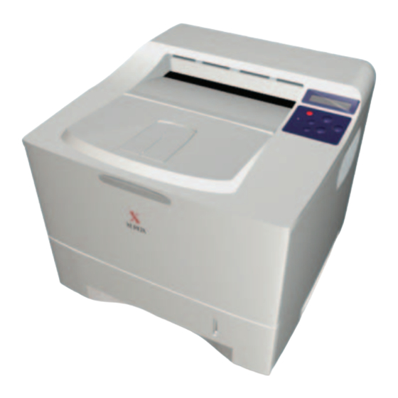
The Xerox Phaser 3425 Laser Printer Service Manual is the primary document used for repairing, maintaining, and troubleshooting the printer. To ensure complete understanding of this product, participation in Xerox Phaser 3425 Laser Printer Service Training is strongly recommended. Phaser 3425 Laser Printer Shown With Optional Tray 3... -
Page 23: Printer Configurations
Printer Configurations The Phaser 3425 Laser Printer combines a 25 page per minute monochrome print engine with an image processor supporting PostScript 3**, PCL6 (Windows), and KSC5843, and KSSM (DOS) page description languages. The printer supports resolutions of 600 and 1200 dots-per-inch (dpi) image quality. -
Page 24: Parts Of The Printer
Exterior Tray 1 (MPT) Output Support Tray 2 (500 Sheet Feeder) Front Panel Tray 3 (Optional 500 Sheet Feeder) Top Output Tray (Facedown) Paper Level Indicator Top Cover Right (Main Board) Cover Print Cartridge Phaser 3425 Laser Printer Service Manual... -
Page 25: Phaser 3425 Front Panel Configuration
Phaser 3425 Front Panel Configuration The front panel consists of a 2 x 16 display, six functional buttons, and an LED. The buttons navigate the menu system, perform functions, and select modes of operation for the printer. LED indicator: Green = Ready to Print or Flashing Green = Receiving, Processing Data, ■... -
Page 26: Phaser 3425 Laser Printer Rear View
Front Panel Shortcuts Mode Press this selection at Power On Enter Service Diagnostics OK (hold the OK button down) Phaser 3425 Laser Printer Rear View Power Switch Power Receptacle Rear Panel Interface Ports Rear Jam Access Door Rear Panel Configuration Interfaces ■... -
Page 27: Main Board
Main Board The following components need to be transferred from the old board when installing a new Main Board in the printer. Note NVRAM parameters are not transferable to the replacement board. These include Serial Number and Copy Count. Serial number can be reinstalled via CentreWare if the NIC Board is installed, or by a downloadable PJL command. -
Page 28: Service Parts
Service Parts Feed Roller Fuser Assembly Transfer Roller Phaser 3425 Laser Printer Service Manual... -
Page 29: Consumables
Consumables Print Cartridge General Information... -
Page 30: Supply Life Counter Behavior
Life ratings are based on 5% coverage and an average 4 page job length. Consumables Print Life High Capacity 10,000 Print Cartridge* Standard Capacity 5,000 Service Parts 125,000 Fuser Assembly 125,000 Transfer Roller 125,000 Feed Roller Kit 1-10 Phaser 3425 Laser Printer Service Manual... -
Page 31: Printer Specifications
Printer Specifications Physical Dimensions and Clearances Print Engine Dimensions Value Height: 326 mm (12.90 inches) (without optional cassette) Width: 386 mm (15.20 inches) Depth: 446 mm (17.56 inches) Weight: 13.7 Kg (30.2 Lbs.) Optional Feeder Cassette Dimensions Value Height: 158 mm (6.22 inches) Width: 380 mm (14.96 inches) Depth:... -
Page 32: Functional Specifications
450 W or less 450 W or less Print Mode Max. 100 W or less 100 W or less Ready Mode Fuser On 15 W or less 15 W or less Sleep Mode Fuser Off 1-12 Phaser 3425 Laser Printer Service Manual... -
Page 33: Environmental Specifications
Environmental Specifications Characteristic Specification Optimal print-quality range: 17º to 26º C (62º to 80º F) Temperature: Operating 10º C to 32º C (50º F to 89º F) Storage Unpacked 5º C to +35º C (41º F to 95º F) Packed 24 month maximum -20º... -
Page 34: Media And Tray Specifications
Other sizes will be handled through Tray 1 with use of the custom Media size option. Tray Universal Tray Tray 1 Capacity 500 Sheets 100 Sheets Standard Paper 100 Sheets 50 Sheets Transparency 10 each Envelopes 1-14 Phaser 3425 Laser Printer Service Manual... -
Page 35: Theory Of Operation
Theory of Operation In this chapter... Overview of the Phaser 3425 Laser Printer ■ Print Modes ■ Printer Controls ■ Paper Path of the Printer ■ Duplex Paper Path ■ Chapter... -
Page 36: Overview Of The Phaser 3425 Laser Printer
Overview of the Phaser 3425 Laser Printer Summary of the Printing Process The Phaser 3425 Laser Printer is a desktop monochrome laser printer, applying the principals of an electrophotographic system. The system, comprising a drum and developing unit, places the toner image onto print media producing a monochrome image. -
Page 37: Print Modes
Sensor 6.Transfer 5.Pre-Transfer Print Modes The Phaser 3425 Laser Printer provides four print modes: draft, 300, 600, and enhanced. Print modes are front panel selectable. ■ Draft mode: Uses a combination of reduced toner output and the lowest resolution (300 x 300 dpi) to extend print cartridge life. -
Page 38: Printer Controls
ON is Tray 2. The tray in the optional Feeder is Tray 3. If the default tray is empty, the printer will automatically switch to any other tray that contains paper unless Tray Chaining is set to OFF. Phaser 3425 Laser Printer Service Manual... -
Page 39: Laser Light Intensity Control
Parameter correction and control over the entire printing process is called “process control”. In the Phaser 3425 Laser Printer, the process is controlled by using feedback circuits to monitor changes in the printing environment for each section (i.e. charging, development, transfer, fixing, etc.) and adjusting the appropriate supply voltages to... -
Page 40: Paper Path Of The Printer
A door at the rear of the printer provides access for jam clearance. The diagram below shows the paper path through the Phaser 3425 Laser Printer and identifies the major components. The simplex paper path is shown in black and the duplex path is shown in grey. -
Page 41: Major Assemblies And Functions
Major Assemblies and Functions The Phaser 3425 Laser Printer contains several subsystems. Each subsystem contains Service Parts identified in the parts list in Chapter 9 of this manual. For information on repairing or replacing sub-assemblies and Service Parts, refer to the Removal and Replacement Procedures in Chapter 8 of this manual. -
Page 42: Power Supply Board
SELI N* ST ROB E* A UT OFD* U ART I NI * H VPS Int er face PAN EL 5Pin Co mputer Power Supply Board L CD Pane l Main Board Wiring Diagram Phaser 3425 Laser Printer Service Manual... - Page 43 Print Engine Control Function The Print Engine Control function is composed of two sections: ■ Power Distribution ■ Engine Control The power distribution section receives AC voltage and creates the required DC outputs (3.3 VDC, 5 VDC, and 24 VDC) to power the printer components. It also supplies AC voltage to the Fuser assembly.
-
Page 44: Print Cartridge
■ Beam Detector: synchronizes the left margin. ■ Optical Lens System: focuses the laser beam onto the surface of the drum. ■ Mirrors: reflect the laser beam onto the surface of the drum. 2-10 Phaser 3425 Laser Printer Service Manual... -
Page 45: Transfer Roller
Transfer Roller The transfer subsystem consists of the Pre-Transfer Lamp (PTL) and the Transfer Roller. The PTL exposes the drum surface after the latent image has been developed to lower surface potential of the drum. This provides enhanced transfer efficiency. The transfer roller provides a high positive potential on the back of the print media. -
Page 46: Paper Feed Sequence
When printing the first side of a duplex print job, the drive direction is reversed when the exit sensor is actuated. Paper is then directed into the Duplex Unit for printing on the second side. 2-12 Phaser 3425 Laser Printer Service Manual... -
Page 47: Fuser Exit Sensor
Fuser Exit Sensor The Exit Sensor monitors the paper movement. If the paper takes too long getting to the sensor, or it stays on the sensor too long, the Main Board will shut down the machine, the Control Panel LED will blink red, and a JAM 2 error message will display on the Control Panel. - Page 48 2-14 Phaser 3425 Laser Printer Service Manual...
-
Page 49: Error Messages And Codes
Error Messages and Codes In this chapter... Introduction ■ Servicing Instructions ■ Service Diagnostics ■ Error Messages and Codes Summary Table ■ Chapter... -
Page 50: Introduction
Introduction This section covers troubleshooting procedures for the Phaser 3425 Laser Printer front panel error messages and codes. Only jams and fatal errors will produce an associated numeric code. Error messages and codes are generally specific, making it important that service personnel and users record errors exactly when reporting problems with the printer. -
Page 51: Accessing Fault History
When an error first occurs, record the error message and code then cycle power to the printer to see if the error recurs. Fault History can be accessed one of two ways: Accessing Fault History View the printer’s fault history on the front panel. Troubleshooting -->... -
Page 52: Servicing Instructions
Use the Wiring Diagrams and Plug/Jack Locator to locate test points. Take voltage readings at various test points as instructed in the appropriate troubleshooting procedure. Use the "Front Panel Test Print" on page 5-3, to isolate problems with the Main Board. Phaser 3425 Laser Printer Service Manual... -
Page 53: Using The Troubleshooting Procedures
Step 4: Correct the Problem Use the Parts List to locate a part number. Use the Removal and Replacement Procedures to replace the part. Step 5: Final Checkout Test the printer to be sure you have corrected the initial problem and there are no additional problems present. -
Page 54: General Notes On Troubleshooting
When a troubleshooting procedure instructs you to replace a non-spared component and that component is part of a parent assembly, you should replace the entire parent assembly. Phaser 3425 Laser Printer Service Manual... -
Page 55: Voltage Measurements
Voltage Measurements Power and signal grounds are connected to the frame ground. All circuit troubleshooting can be performed using the metal frame (chassis) as the grounding point. To locate connectors or test points, refer to "Wiring Diagrams" on page 10-1 for more information. Unless otherwise specified, the following voltage tolerances are used within this section: Stated... -
Page 56: Service Diagnostics
Service Diagnostics The Phaser 3425 Laser Printer has built-in diagnostics to aid in troubleshooting problems with the printer. The Service Diagnostics Menu provides a means to test sensors, motors, switches, clutches, fans and solenoids. Diagnostics also contain built-in test prints, cleaning procedures, printer status and some NVRAM access. -
Page 57: Service Diagnostic Front Panel Button Descriptions
Service Diagnostic Front Panel Button Descriptions Button Function Returns to the prior higher level menu structure, if available. BACK If help text is displayed on the front panel, pressing BACK will restore the current menu item and remove the help text. Terminates the current test. - Page 58 (ON / OFF) Main motor runs 2 sec before clutch is energized to enable checking the clutch state. If Tray 3 not installed, test does not run. “Tray 3 Not Installed” displays. 3-10 Phaser 3425 Laser Printer Service Manual...
- Page 59 Function Function Function Description Display Sensor Paper Size Compares selected media size with Paper size: Sensor size actually loaded. If Tray 3 is Letter installed, both Tray 2 and Tray 3 sizes will display. Tray 1 NP With tray down, touch sensor and Tray 1 W/ Sensor confirm message changes to “Tray 1...
- Page 60 Print Cycle Cycle Cartridge. Ranges are as follows: [XXX] 10K Cartridge: 78,000 = Toner Low ■ 92,000 = Replace Cart. ■ 5K Cartridge: 39,000 = Toner Low ■ 46,000 = Replace Cart. ■ 3-12 Phaser 3425 Laser Printer Service Manual...
-
Page 61: Error Messages And Codes Summary Table
Error Messages and Codes Summary Table Error Messages and Codes Summary Table Error Type Front Panel Message Code Fuser Fuser Failure (open/disconnected Fuser) 0x56 Engine Fuser Low Heat Error 0x57 Engine Fuser Over Heat Error 0x58 Laser Errors Laser Failure (Polygon motor not ready) 0x5A Jam Errors Jam At Tray [1] [2] [3]/ Remove All Paper... -
Page 62: Fuser Failure/Low Heat/Or Overheat/ 0X56/0X57/0X58
Go to Step 3. Is thermostat open? Check resistance of thermistor. Is Replace Fuser. Go to Step 4. thermistor open? Check resistance of heat lamp. Is heat Replace Fuser. Replace Main lamp open? Board. 3-14 Phaser 3425 Laser Printer Service Manual... -
Page 63: Lsu Error Or 0X5A
LSU Error or 0x5A The printer’s front panel displays “Laser Failure”. The LSU has been removed, reseated, and locked into place. Any obstructions, media, or debris has been removed from the paper path. Printer power has been cycled and the error still appears. Troubleshooting Reference Applicable Parts Wiring and Plug/Jack Map References... -
Page 64: Jam At Tray [1] [2] [3] Or 0X01
Check the surface of the pick-up rollers for Clean rollers with Replace Main dirt or damage. Are the rollers dirty or a soft cloth very Board. damaged? slightly dampened with water or replace if damaged. 3-16 Phaser 3425 Laser Printer Service Manual... -
Page 65: Jam At Top(0X02) Or Jam At Exit (0X03)
Jam At Top(0x02) or Jam At Exit (0x03) The printer’s front panel displays “Jam At Top or Jam At Exit”. Any obstructions, media, or debris has been removed from the paper path. Printer power has been cycled and the error still appears. Troubleshooting Reference Applicable Parts Wiring and Plug/Jack Map References... -
Page 66: Jam At Duplex (0X04) Or Jam At Tray (0X05)
If paper jam occurs at the Feed Roller, use Replace the Replace the the embedded diagnostics to check Power Supply Duplex Sensor. operation of the Duplex Sensor. Board. Does the sensor operate correctly? Does problem recur? Replace the Main Complete Board. 3-18 Phaser 3425 Laser Printer Service Manual... -
Page 67: Output Tray Is Full Or 0X44
Output Tray Is Full or 0x44 The printer’s front panel displays “Output Tray Is Full”. The output tray has been emptied of all paper. Printer power has been cycled and the error still appears. Troubleshooting Reference Applicable Parts Wiring and Plug/Jack Map References Tray Full Sensor "Print Engine Interconnect Diagram"... -
Page 68: Replace Print Cartridge (0X53) Or Invalid Print Cartridge (0X55)
Replace Print Cartridge (0x53) or Invalid Print Cartridge (0x55) The printer’s front panel displays “Replace Print Cartridge”. The Print Cartridge has been replaced with the correct Xerox Print Cartridge. Printer power has been cycled and the error still appears. Troubleshooting Reference... -
Page 69: General Troubleshooting
General Troubleshooting In this chapter... Introduction ■ Preliminary Procedures ■ Front Panel Troubleshooting ■ Paper Size Switch Assembly ■ Power Supply Troubleshooting ■ Media Jams and the Paper Path ■ Chapter... -
Page 70: Introduction
Are consumables replaced at the intervals recommended in "Consumables" on page 1-9? Is the Print Cartridge properly installed? Are all of the printer assemblies in place and are all printer covers and doors firmly closed? Phaser 3425 Laser Printer Service Manual... -
Page 71: Front Panel Troubleshooting
Front Panel Troubleshooting No Front Panel Display after Power is Turned ON Verify that power cord is securely plugged into both the printer and the grounded, three prong AC outlet with the appropriate power available. Ensure that all covers are securely closed. Verify that Top Cover, Print Cartridge, and Fuser Gate interlocks are functional. -
Page 72: Front Panel Continually Displays "Output Tray Is Full
Paper size and tray installation is determined by a combination of ON/OFF statuses of the upper, middle, and lower switches of the Switch Paper Size Assembly. Paper size Switches Upper Middle Lower LEGAL14" LEGAL13" EXECUTIVE LETTER A5 (for reference only, supported in Tray 1 only) No Tray Phaser 3425 Laser Printer Service Manual... -
Page 73: Power Supply Troubleshooting
Power Supply Troubleshooting Troubleshooting References Applicable Parts Wiring and Plug/Jack Map References Power Supply Board AC Switch Harness Assembly Procedure Step Action and Questions Check the voltage at the AC wall outlet. Is Go to Step 2. Notify the there approximately 110 VAC (or 220 VAC if customer of the printer is a 220 V model) at the AC wall improper AC... -
Page 74: Media Jams And The Paper Path
Is Tray 1 Solenoid operational? Refer to Go to Step 5. Replace Tray 1 "Service Diagnostics Menu Map" on Solenoid. page 3-9. Are the feed roller or retard/drag pads Clean if dirty. Replace damaged or dirty? damaged parts. Phaser 3425 Laser Printer Service Manual... -
Page 75: Paper Mis-Feed From Tray 2
Paper Mis-feed from Tray 2 Troubleshooting References Applicable Parts Wiring and Plug/Jack Map References Main Board Tray 2 Pick-Up Roller Tray 2 Assembly Procedure Step Action and Questions Is paper loaded correctly? Go to Step 2. Load paper correctly. Is the tray damaged? Replace Tray 2 Go to Step 3. -
Page 76: Paper Mis-Feed From Tray 3 (Optional Feeder)
Replace Tray 3 Solenoid actuates? Refer to "Service Assembly. Diagnostics Menu Map" on page 3-9. Are the feed roller or retard/drag pads dirty ? Clean if dirty. Replace Tray 3 Assembly Replace Main Board. Phaser 3425 Laser Printer Service Manual... -
Page 77: Jam At Tray [1] [2] [3] (Jam 0)
Jam At Tray [1] [2] [3] (Jam 0) Paper jams at or just after the Registration Sensor. Troubleshooting References Applicable Parts Wiring and Plug/Jack Map References Registration/Feed Sensor Actuator Transfer Roller Registration Assembly Print Cartridge Main Board Procedure Step Action and Questions Is the Registration/Feed Sensor Actuator Repair or Go to Step 2. -
Page 78: Jam At Top (Jam 1)
Go to Step 5. Replace Fuser freely when the motor is on? Assembly. Use the embedded diagnostics to check the Replace Power Replace Fuser Fuser Exit Sensor. Is the sensor operational? Supply Board. Exit Sensor. 4-10 Phaser 3425 Laser Printer Service Manual... -
Page 79: Jam At Exit (Jam 2)
Jam At Exit (Jam 2) Paper jams in the Fuser Assembly outlet or the Exit Roller Assembly. Troubleshooting References Applicable Parts Wiring and Plug/Jack Map References Exit Sensor Actuator Fuser Assembly Exit Transport Assembly Main Board Procedure Step Action and Questions Is the Exit Sensor Actuator damaged or binding? Repair or Go to Step 2. -
Page 80: Jam At Duplex (Duplex Jam 1)
Is the Transport Roller Assembly operational Go to Step 5. Replace (rotates freely without binding)? Transport Roller Assembly. Use the embedded diagnostics to check the Replace Main Replace Exit Fuser Exit Sensor. Is the sensor operational? Board. Sensor. 4-12 Phaser 3425 Laser Printer Service Manual... -
Page 81: Jam At Tray/Remove Tray 2 (Duplex Jam 2)
Jam At Tray/Remove Tray 2 (Duplex Jam 2) Paper Jam between the Duplex Feed Rollers and the Registration Rollers. Troubleshooting References Applicable Parts Wiring and Plug/Jack Map References Duplex Exit Sensor Actuator Duplex Assembly Feed Roller Assembly Print Engine Controller Board Procedure Step Action and Questions... -
Page 82: Crum Toner Error
Interconnect Board and CN6 on the Main Board. Harness. Does the harness show continuity? Check Print Cartridge. Does the cartridge Replace Print Replace Print contain toner and appear to be operating Cartridge Cartridge. properly? Interconnect Board. 4-14 Phaser 3425 Laser Printer Service Manual... -
Page 83: Print-Quality Troubleshooting
Print-Quality Troubleshooting In this chapter... Print-Quality Problems Overview ■ Defects Associated with Specific Printer Components ■ Front Panel Test Print ■ Print-Quality Troubleshooting ■ Chapter... -
Page 84: Print-Quality Problems Overview
See the approved media list from, "Xerox Supplies" on page 9-25 for media that has been tested and approved for use in the Phaser 3425 Laser Printer. If the print quality defect is still present when printing on approved media from an unopened ream of paper, then components, software applications, and environmental conditions need to be researched. -
Page 85: Front Panel Test Print
Fuser ■ Hot or Cold Offsetting ■ Repeating Defects ■ Voids Repeating Defects Distance Assembly Component between Defects Typical Defect Print Cartridge Developer Roller 49 mm (1.93 in.) Horizontal image band Drum 95 mm (3.74 in.) White spots on black image or black spots on white Drum Charge Rollers 38 mm (1.50 in.) -
Page 86: Deletions
Deletions Inspect the test print for the presence of deletions or unprinted spots. If these are found go to Spot or Vertical Deletions on page 5-9. Phaser 3425 Laser Printer Service Manual... -
Page 87: Fusing
Fusing Rub the image three times at the indicated points with a soft cloth or tissue. The toner should not lift off of the surface of the print. If the image smears or toner lifts off the image onto the cloth, refer to Unfused Image on page 5-10. Resolution Observe the three resolution check points on several test prints. -
Page 88: Registration And Skew
Check the test print in the indicated areas for loss, stretching, or distortion of the image in bands across the process direction that make the image seem distorted, blurred, or compressed. If these faults are observed refer to Skips/Smears on page 5-10. Phaser 3425 Laser Printer Service Manual... -
Page 89: Print-Quality Troubleshooting
Print-Quality Troubleshooting The following table provides examples or descriptions of various image or printing defects that may be observed in the Phaser 3425 Laser Printer. The table also lists possible causes and solutions. Image Defect Possible Cause Solution Seal tape was not... - Page 90 Ensure that drum contamination. contact is clean and undamaged. Inspect the Transfer Roller spring ■ tension and bearing contacts. Remove Laser assembly, clean ■ window or replace assembly as necessary . Replace Power Supply Board. ■ Phaser 3425 Laser Printer Service Manual...
- Page 91 Image Defect Possible Cause Solution Print Cartridge Replace the Print Cartridge. Black Spots/Marks: ■ ■ There are spots and/or Fuser assembly ■ NOTE: Refer to "Defects marks of toner on the Paper transports ■ Associated with Specific Printer printed side of the page. Transfer Roller ■...
- Page 92 Recommended Media when printing on ■ Verify transparency meets printer Transfer roller voltage ■ transparencies. ■ specifications. Inspect the Transfer Roller spring ■ tension and bearing contacts. Replace Power Supply Board. ■ 5-10 Phaser 3425 Laser Printer Service Manual...
-
Page 93: Adjustments And Calibrations
Adjustments and Calibrations In this chapter... Margin Calibration ■ Resetting NVRAM ■ Chapter... -
Page 94: Margin Calibration
Margin Calibration The Margin Calibration has no effect on the printer’s image registration. Image registration is not adjustable on the Phaser 3425 Laser Printer. Margins - Simplex Top/Left The Simplex Top and Left adjustment provides a method of changing the margin settings when a print driver is not being used. -
Page 95: Cleaning And Maintenance
Cleaning and Maintenance In this chapter... Service Preventive Maintenance Procedure ■ Recommended Tools ■ Cleaning ■ Printing a Cleaning Sheet ■ Chapter... -
Page 96: Service Preventive Maintenance Procedure
Remove any debris or foreign objects. Remove any loose toner from the interior of the printer using a Type II toner vacuum only. Remove and clean the paper trays. Clean pick rollers with a slightly damp, lint-free cloth. Phaser 3425 Laser Printer Service Manual... -
Page 97: Printing A Cleaning Sheet
Printing a Cleaning Sheet If you are experiencing blurred, faded, or smeared printouts, you may be able to correct the problem by printing either or both of the cleaning sheets available in the Troubleshooting/Service Tools Fuser Clean menu. The sheet cleans toner Print Cart Clean debris out of the Fuser, and the sheet cleans the drum in the Print... - Page 98 Phaser 3425 Laser Printer Service Manual...
-
Page 99: Service Parts Disassembly
Service Parts Disassembly In this chapter... Overview ■ General Notes on Disassembly ■ Removing Service Parts and Consumables ■ Print Engine Disassembly ■ Chapter... -
Page 100: Overview
When needed, the orientation of the printer is called out in the procedure for locating printer parts. Refer to the printer orientation graphic for locating the right, left, front and back sides of the printer. Back Left Right Front Phaser 3425 Laser Printer Service Manual... -
Page 101: General Notes On Disassembly
General Notes on Disassembly Preparation Before you begin any Removal and Replacement Procedure: Switch OFF the printer power and disconnect the power cord from the wall outlet. Remove the Imaging Unit and protect it from exposure to light by covering it with a light proof bag or by placing it in a light-tight container. -
Page 102: Removing Service Parts And Consumables
Removing Service Parts and Consumables Routine Maintenance Items for the Phaser 3425 Laser Printer include the Transfer Roller and Fuser Assembly. Consumables consist of the Print Cartridge. Print Cartridge Removal (PL 9.1.8) Power down the printer and disconnect the power cord from the wall outlet. -
Page 103: Fuser Removal Pl 9.3.40)
Lift the lever on the Bearing Clip at each end of the Transfer Roller. Caution The gear on the end of the Transfer Roller shaft is not secured in place. Hold the gear when removing the roller to prevent it from falling into the printer. Note The 2 bearing clips are not interchangeable. - Page 104 If the Fuser is not fully seated, the fins on the inside of the rear cover will hit the Fuser when the cover is closed. Phaser 3425 Laser Printer Service Manual...
-
Page 105: Print Engine Disassembly
Print Engine Disassembly Right Cover Assembly (PL 9.2.2) Power down the printer and remove the power cord from the wall outlet. Remove the 2 screws securing the Right Cover (1) to the back of the printer. Slide the cover toward the back of the printer to disengage the 3 retaining hooks on the lower edge of the cover, then lean the top of the cover outward and remove it from the printer. -
Page 106: Left Cover Assembly (Pl 9.2.4)
Slide the cover toward the back of the printer to disengage the 3 retaining hooks on the lower edge of the cover, then lean the top of the cover outward and remove it from the printer. Phaser 3425 Laser Printer Service Manual... -
Page 107: Top Cover Assembly (Pl 9.2.1)
Top Cover Assembly (PL 9.2.1) Remove the Print Cartridge (page 8-4) and protect it from light. Remove the Right Cover Assembly (page 8-7) and the Left Cover Assembly (page 8-8) from the printer. Open Tray 1, the rear cover, and the front section of the Top Cover. Note If the NIC Card is installed, remove it ( page 8-17) to access the connectors on the Main Board. -
Page 108: Tray 1 Cover Assembly (Pl 9.1.2)
Power down the printer and remove the power cord from the wall outlet. Open Tray 1. Caution Use caution when pushing outward on the top of the slot tracks in the next Step. If you exert too much pressure you can break the track. 8-10 Phaser 3425 Laser Printer Service Manual... - Page 109 Close the Tray 1 cover about half way then push outward on the top of the left slot track that the link pin rides in and disconnect the Tray Link from the left cover slot. Next, flex the top of the right track and release right Tray Link. Tray Link Link Pin Slot Track...
-
Page 110: Retard Assembly (Pl 9.3.7)
Sensor and Actuator from the printer. Front (Inner) Cover (PL 9.2.5) Note Tray 2 must be removed in order to remove the Front Cover. Remove the Print Cartridge (page 8-4) and protect it from light. 8-12 Phaser 3425 Laser Printer Service Manual... -
Page 111: Tray 1 Lift Plate (Pl 9.1.3)
Remove the Tray 1 Cover Assembly (page 8-10). Remove the Top Cover Assembly (page 8-9). Disconnect the Tray 1 Lift Plate Links from the Tray 1 Lift Plate by pulling outward on the end of the Link arms where they connect to the lift plate. Rotate each Link to align the key with the slot in the frame mounting hole and remove the Links. -
Page 112: Rear Cover Assembly (Pl 9.2.3)
You can also pry the cover end of the strap off the retainer and slide it free of the cover while leaving it and the screw attached to the rear of the printer. 8-14 Phaser 3425 Laser Printer Service Manual... -
Page 113: Front Panel Assembly (Pl 9.2.1.8)
Rotate the rear cover until the flat surface of the left hinge pin (refer to standard orientation drawing on page 8-2) aligns with the slot as shown in ➀ below. Pull up on the left side of the cover to free the left hinge pin. Slide the rear cover to the left to free the right hinge pin (see ➁... -
Page 114: Cover Open Interlock Switch (Pl 9.2.1.16)
Remove the Print Cartridge (page 8-4) and protect it from light. Remove the Top Cover Assembly (page 8-9). Open the front section of the Top Cover to access the Interlock Switch cover. 8-16 Phaser 3425 Laser Printer Service Manual... -
Page 115: Nic Board (Pl 9.1.41)
Using a small flat blade screwdriver, pry outward to release the retainers (6) that secure the interlock switch cap, and pull the cap free of the cover. Interlock Switch Switch Cap Remove the Cover Open Interlock Switch NIC Board (PL 9.1.41) Remove the Right Cover Assembly (page 8-7). -
Page 116: Main Board (Pl 9.1.10)
Tray 3 CN14 (Not Used) Remove 6 screws securing the Main Board to the Main Board Bracket (4 on the right side of the printer and 2 from the rear of the printer). 8-18 Phaser 3425 Laser Printer Service Manual... -
Page 117: Main Drive Assembly (Pl 9.1.11)
Position the retainers on the parallel port connector straight out from the connector for removal. Move the board toward the front of the printer so the connectors clear the bracket and remove the Main Board to the right. Note NVRAM parameters are not transferable to the replacement board. These parameters include Serial Number and copy count. - Page 118 Remove the screw securing the Cover Interconnect Board to the Main Drive and move it out of the way. Remove 6 screws that secure the Main Drive to the printer chassis, and remove the Main Drive. 8-20 Phaser 3425 Laser Printer Service Manual...
-
Page 119: Tray 2 Solenoid (Pl 9.1.28)
Replacement Notes Note A ground wire and a discharge capacitor are secured to the Main Drive Assembly by 2 of the mounting screws. Note the position for reassembly. Note Seat the right side of the Main Drive first, then work the left side into position while aligning the gears. -
Page 120: Paper Size Sensor (Pl 9.3.36)
Exit Motor Drive Assembly (PL 9.1.20) Remove the Print Cartridge (page 8-4) and protect it from light. Remove the Top Cover Assembly (page 8-9). Disconnect the Exit Motor Drive harness connector from the Exit Motor. 8-22 Phaser 3425 Laser Printer Service Manual... -
Page 121: Main Fan Assembly (Pl 9.1.19)
Remove 3 screws that secure the Exit Motor Drive Assembly to the printer chassis and remove the drive assembly. Caution Do not lose the thermal insulating washers on each of the mounting screws between the screw head and the motor. Main Fan Assembly (PL 9.1.19) Remove the Top Cover Assembly (page 8-9). -
Page 122: Sub Fan Assembly (Pl 9.3.35)
If you wish, you can loosen the screws securing the Laser Assembly and tilt it to provide additional access to remove the cable. This will be necessary when routing the cable back under the Laser Assembly during reinstallation. 8-24 Phaser 3425 Laser Printer Service Manual... -
Page 123: Exit Roller Assembly (Pl 9.3.21) Transport Roller Assembly (Pl9.3.24)
Remove 1 screw securing the Fan retainer (stopper) and remove the fan to the left while feeding the cable through the printer from the right side. Stopper Sub Fan Reinstallation Notes Note If not already done during removal, loosen the screws securing the Laser Assembly sufficiently to route the fan cable under the laser. - Page 124 Lift the Exit Shaft Assembly out of the exit frame. Caution The Exit Idler Roller Assemblies are not captured in the exit frame and can be dropped. Lift the Exit Idler Roller Assemblies out of the exit frame. 8-26 Phaser 3425 Laser Printer Service Manual...
-
Page 125: Laser Assembly (Pl 9.1.16)
Using a small flat blade screwdriver spread the plastic latch hooks on the bottom of the bearing while pulling the left end of the Transport Roller Shaft Assembly to the rear. Continue pulling the Transport Roller Shaft Assembly to the rear to remove it from the center bearing. - Page 126 Carefully peel back the foam pad securing the laser harness to the bottom of the Laser Assembly and disconnect the 2 harness connectors from the Laser. Note If the foam pad is damaged during removal, it is not critical to unit performance. 8-28 Phaser 3425 Laser Printer Service Manual...
-
Page 127: Print Cartridge Interconnect Assembly (Pl 9.3.53)
Print Cartridge Interconnect Assembly (PL 9.3.53) Remove the Laser Assembly (page 8-27). If the NIC Board is installed, remove it (page 8-17). Disconnect CN 4, CN 7, CN 8, and CN 9 from the Print Cartridge Interconnect Assembly. Disconnect CN 6 from the Main Board. Remove the 3 screws securing the Print Cartridge Interconnect Assembly and remove the Assembly. -
Page 128: Registration Transport Assembly (Pl 9.1.9)
The gear cap is the same color black as the printer frame and can be difficult to see. Look at the right end of the Registration Transport Assembly and you will see the cap just to the right of the bearing. 8-30 Phaser 3425 Laser Printer Service Manual... -
Page 129: Registration Sensor (Pl 9.7.10)
Lift the Registration Transport Assembly out of the printer. Registration Sensor (PL 9.7.10) Remove the Registration Transport Assembly (page 8-30). Remove 1 screw (accessed from the bottom of the Assembly), that secures the Registration Sensor to the Registration Transport Assembly and remove the Sensor Holder and the Sensor. - Page 130 Remove 2 screws securing the Tray 1 Solenoid (item 1) to the chassis and remove the solenoid. Note The ground wire will also be removed at this time. Be sure to replace it when replacing the solenoid. 8-32 Phaser 3425 Laser Printer Service Manual...
- Page 131 Remove 2 screws, one at each end of the Tray 1 Pick Up Rack, and unsnap the rack with the 2 bushings that secure the rack to the Tray 1 Feed Roller Shaft. Bushing Tray 1 Pick Up Rack Remove 1 screw on the right side of the printer that secures the bracket over the right end of the Feed Roller Shaft.
- Page 132 ➀ below. Pull the left end of the shaft forward while sliding the right end of the shaft free as shown by ➁ below. Remove the Pick Up Assembly from the printer. 8-34 Phaser 3425 Laser Printer Service Manual...
-
Page 133: Tray 1 Pick Roller (Pl 9.3.2.4)
Tray 1 Pick Roller (PL 9.3.2.4) Remove the Inner Front Cover (page 8-12). Release the securing tabs and push both idle rollers outward from the sides of the Pick Roller as shown by ➀ below. Note If it is necessary to rotate the Pick Roller for removal, release the solenoid, then rotate the shaft gear clockwise. -
Page 134: Tray 2 Retard Assembly (Pl 9.3.7)
Remove 2 screws and drop the Retard Roller Frame Assembly. Roller Ass'y Tray 2 Paper Pick Assembly (PL 9.3.67) Remove the Front (Inner) Cover Assembly (page 8-12). Remove the Main Drive Assembly (page 8-19). 8-36 Phaser 3425 Laser Printer Service Manual... - Page 135 On the right side of the printer, press down the retaining tab and remove the Feed Roller Shaft Gear Assembly from the Feed Roller Shaft. Service Parts Disassembly 8-37...
- Page 136 Turn the printer upside down, remove 4 screws, and remove the 2 Bottom Cross Bars from the printer. Caution The Tray Full actuator is exposed with the top cover removed. Be careful when you turn the printer over to avoid damaging the actuator. 8-38 Phaser 3425 Laser Printer Service Manual...
- Page 137 With the printer upside down, disconnect 2 springs from the pickup assembly to the front corners of the Duplex Guide Plate. Using a screwdriver, pry up the locking tab and remove the stopper on the left side of the printer. Remove the screw securing the ground wire on the right side of the Duplex Guide Plate.
- Page 138 Remove 4 screws securing the Paper Pick Assembly, slide the assembly to the right side of the printer, lift the left end and slide the assembly up and out to the left side of the printer. 8-40 Phaser 3425 Laser Printer Service Manual...
-
Page 139: Tray 2 Pick Roller (Pl 9.3.67.3)
Reassembly Notes Note When reinstalling the Duplex Guide Plate, make sure the plate is past the flange before you reinstall the springs. Note Be sure that you reinstall the ground wire on the right side of the Duplex Guide Plate. Tray 2 Pick Roller (PL 9.3.67.3) Remove the Tray 2 Paper Pick Assembly (page 8-36). -
Page 140: Power Supply Board (Pl 9.1.13)
Slide the Tray 2 Paper Out Actuator (item 1) to the left ➀ until the end is free of the retainer clip, then lift up ➁ to remove it from the printer. Right Left 8-42 Phaser 3425 Laser Printer Service Manual... - Page 141 Remove 9 screws and slightly lift the Duplex Assembly from its mounting location. Note The screw that secures the ground wire to the back edge of the assembly is the short machine screw. Caution Do not attempt to remove the Power Supply Board Assembly from the printer until you first disconnect all 5 connectors.
- Page 142 Supply Board, then remove the Power Supply Board Assembly to a work surface with the Power Supply up. Reassembly Notes Note CN3 must be dressed correctly for reassembly. If CN3 is pulled too far forward, assembly will be difficult. 8-44 Phaser 3425 Laser Printer Service Manual...
-
Page 143: Duplex Assembly (Pl 8.8.2)
Duplex Assembly (PL 8.8.2) Remove the Power Supply Board (page 8-42). Remove 4 screws securing the Power Supply Board to the Duplex Assembly and remove the board. Power Supply Board RH Guide (Duplex) LH Guide (Duplex) Exit Sensor (PL 9.3.62) Remove the Power Supply Board (page 8-42). - Page 144 8-46 Phaser 3425 Laser Printer Service Manual...
-
Page 145: Parts Lists
Parts Lists In this chapter... ■ Using the Parts List ■ Print Engine Parts ■ Xerox Supplies ■ Chapter... -
Page 146: Using The Parts List
Using the Parts List 1. No.: The callout number from the exploded part diagram. 2. Part Number: The material part number used to order specific parts. 3. Qty: This number represents the parts per printer, not the number of parts supplied in the actual part order. -
Page 147: Print Engine Parts
Print Engine Parts Main Unit Phaser 3425 Laser Printer Service Manual... - Page 148 Service Parts List 9.1 Main Unit Name/Description Part Number Base Housing 2.1 Part # 002N02468 T ray 1 Cover Assy (with 2-1, 2-2) 2.2 Part # 002N02469 T ray 1 Assembly (with 3-1 ~ 3-6) 050K55430 Tray 1 Link (Left) Tray 1 Link (Right) Paper Tray 109R00722...
- Page 149 Reg Clutch 121E19270 PMO Cap TR PBA Sub Cover Joint Bracket-P Shaft MP Bearing Pick Up Gear Pick Up Cam E-Ring CBF Harness SMPS CBF Harness MPF Joint Network Interface Fan DC (Sub) 127N07300 Phaser 3425 Laser Printer Service Manual...
-
Page 150: Covers
Covers 1-3-2 1-3-3 1-3-4 1-3-5 1-3-1 1-3-6 1-3-3 1-3-10 1-3-7 1-3-9 1-1-4 1-1-3 1-3-10 1-1-1 1-3-8 1-1-2 1-2-1 1-2-2 Parts Lists... - Page 151 Top Cover (with 1-3-1 ~ 1-3-10) 002N02470 Right Cover Assembly (with 2-1 and 2-2) 802K69580 Rear Cover Assembly (with 3-1 ~ 3-8) 802K69591 Left Cover 802E66540 Front Inner Cover 802E66550 Output Tray Cover 802E66560 Phaser 3425 Laser Printer Service Manual...
-
Page 152: Frame 1 Assembly
Frame 1 Assembly Parts Lists... - Page 153 Exit Gear 013E25780 Holder M Bushing Exit Transport Exit Shaft Assy 006N01267 IPR Terminal TR Hawk Cap M Wire PTL Lower PBA Sub PTL2 CBF Harness Thermistor Terminal P PTL Shield P Controller 9-10 Phaser 3425 Laser Printer Service Manual...
- Page 154 Service Parts List 9.3 Frame 1 Assembly (Continued) Name/Description Part Number Nut Hex Cable Tie Actuator Out Full Photo Interrupter Connector Paper Size Sensor Assy (with 36-1 ~ 36-3) 110K14290 Harness Out Full Parts Lists 9-11...
-
Page 155: Frame 2 Assembly
Frame 2 Assembly 9-12 Phaser 3425 Laser Printer Service Manual... - Page 156 Service Parts List 9.4 Frame 2 Assembly Name/Description Part Number MEA Unit Terminal L PMO Bearing Shaft Fuser Assy 110V 126N00248 Fuser Assy 220V 126N00249 PBA Main Zener Interface PWBA 123N00241 IPR P Ground OPC Tray 2 Empty Sensor Assy 130K68290 IPR P GND Solenoid Feed IPR P GND SCF Main...
- Page 157 Service Parts List 9.4 Frame 2 Assembly (Continued) Name/Description Part Number Tray 2 (3) Retard Assy (with 68-1 ~ 68-13) 022E29540 Shaft M Coupling Retard Shaft M Gear Retard Guide M Front 9-14 Phaser 3425 Laser Printer Service Manual...
-
Page 158: Fuser Assembly
Fuser Assembly 1-13 1-11 1-12 1-15 1-18 1-15 1-18 1-17 1-16 1-14 1-10 1-16 1-14 1-10 1-17 Service Parts List 9.5 Fuser Name/Description Part Number Unit Fuser 110V 126N00248 Unit Fuser 220V 126N00249 Parts Lists 9-15... -
Page 159: Main Drive Motor Assembly
Main Drive Motor Assembly Harness-Main Motor Service Parts List 9.6 Main Drive Name/Description Part Number Main Drive Motor Assy 127N07411 9-16 Phaser 3425 Laser Printer Service Manual... -
Page 160: Exit Drive Motor Assembly
Exit Drive Motor Assembly Harness-Motor Service Parts List 9.7 Exit Drive Name/Description Part Number Exit Motor Assy 127K44870 Parts Lists 9-17... -
Page 161: Registration Transport Assy
Service Parts List 9.8 Registration Transport Assy Name/Description Part Number Reg Transport Assy 022N02195 Guide P Regi Lower Roller regi Lower L Shaft Regi Upper Roller M Regi Idle S Roller M Regi Idle L 9-18 Phaser 3425 Laser Printer Service Manual... - Page 162 Service Parts List 9.8 Registration Transport Assy (Continued) Name/Description Part Number Spring TS Paper Guide Guide P Regi Plate Holder M Sensor Photo Interrupter 110K14300 Bush M Roller Regi L E-Ring Bush M Roller Regi L Spring ES CBF Harness MP Empty Washer Plain Cap M Wire PTL Upper Cap M Bushing Actuator...
-
Page 163: Power Supply/Duplex Assembly
Name/Description Part Number Power Supply Board (110 Volts) (with 1 and 2) 105K27081 Power Supply Board (220 Volts) (with 1 and 2) 105K27091 SMPS-V1_HVPS SMPS-V2_HVPS Duplex Roller Assembly (with 2-1 ~ 2-14) 022N02196 9-20 Phaser 3425 Laser Printer Service Manual... -
Page 164: Paper Tray
Paper Tray Service Parts List 9.10 Paper Tray Name/Description Part Number Paper Tray (with 1 ~ 26) 109R00722 Parts Lists 9-21... -
Page 165: Optional Lower Feeder Assembly
Optional Lower Feeder Assembly 35-2 35-3 35-1 18-3 18-4 18-5 18-2 18-1 10-1 10-2 18-6 10-3 10-5 10-4 9-22 Phaser 3425 Laser Printer Service Manual... - Page 166 Service Parts List 9.11 Optional Lower Feeder Name/Description Part Number 500 Sheet Feeder (with paper tray) 097S03131 PMO Frame SCF Tray 3 Feed Assy 059K39120 Spring Pick Up PMO Bushing TX Shaft Pick Up PMO Bearing Shaft MEA Unit Roller Feed Bearing Pick Up PMO Guid Inner SCF Tray 3 Retard Assy...
- Page 167 PMO Cover Dummy SCF CBF Harness SCF GND CBF Harness LIU GND CBF Harness OPE Bush Cable ELA HOU CST Sensor Hawk 16 Harness Paper Size Screw Taptite Screw Taptite Screw Machine E-ring E-ring 9-24 Phaser 3425 Laser Printer Service Manual...
-
Page 168: Xerox Supplies
Xerox Supplies Repair Kits, World Kits, and Repackaging Kits Description Part Number World Kit Phaser 3425 Getting Started Pack Cushion Main Repackaging Phaser 3425 095N00276 Main Shipping Box, Repackaging 095N00275 High-Capacity Print Cartridge Box Standard-Capacity Print Cartridge Box 500-Sheet Paper Tray Box... - Page 169 097S03136 500 Sheet Feeder with Tray 097S03131 Network Interface 500 Sheet Replacement Paper Tray 109R00722 Consumables Description Part Number Print Cartridge - Phaser 3425 Laser Printer Standard-Capacity (5K) 106R01033 High-Capacity (10K) 106R01034 Service Parts Description Part Number Transfer Roller 022E29520...
-
Page 170: Wiring Diagrams
Wiring Diagrams In this chapter... Print Engine Interconnect Diagram ■ Map 1 Main Board ■ Map 2 Connector Board ■ Connection Diagram ■ Chapter... -
Page 171: Print Engine Interconnect Diagram
Print Engine Interconnect Diagram Use the following interconnect diagram to identify specific connectors (CN) within the printer with respect to the main components. 10-2 Phaser 3425 Laser Printer Service Manual... -
Page 172: Map 1 Main Board
Map 1 Main Board CN 10 CN 6 CN 21 CN 4 CN 15 CN 8 CN 20 CN 9 CN 17 CN 5 (not used) CN 18 CN 12 CN 16 RAM DIMM CN 11 ROM DIMM CN 1 CN 14 CN 7 (not used) - Page 173 Map 2 Connector Board Registration Clutch Tray 1 Solenoid CN 14 CN 11 Tray 1 Empty Tray 2 Solenoid Sensor CN 10 CN 13 Tray 2 Out Switch SW 1 Main Board CN 12 10-4 Phaser 3425 Laser Printer Service Manual...
-
Page 174: Connection Diagram
Connection Diagram 10-5... - Page 175 10-6 Phaser 3425 Laser Printer Service Manual...
- Page 176 Index Exit Motor Drive Assembly 8-22 Exit Roller Assembly 8-25 Adjustments Exit Sensor 8-45 Calibrations Fault History Cleaning Frame 1 9-12 Connection Diagram 10-5 Frame 2 9-15 Connector Locator Maps 10-2 Front (Inner) Cover 8-12 Consumables Front Panel Assembly 8-15 Control Panel Assembly 8-15 Front Panel Continually Displays “No...
- Page 177 Parts of the Printer Laser Scanner Unit (LSU) 2-10 Phaser 3425 Front Panel Configuration Left Cover Assembly LSU Error or 0x0000008 3-15 Phaser 3425 Laser Printer Rear View Physical Dimensions and Clearances 1-11 POST Diagnostic Test Descriptions Main Drive 9-16 PostScript NVRAM Resets...
- Page 178 Using the Troubleshooting Procedures Selective Control Voltage Measurements Service Diagnostic Front Panel Key Descriptions Service Diagnostics Service Diagnostics Menu Map Xerox Supplies and Accessories 9-25 Service Diagnostics PostScript NVRAM Resets Service Preventive Maintenance Procedure Servicing Instructions Simplex Jam 1 (0x0000020) or Jam 2...
Need help?
Do you have a question about the Phaser 3425 and is the answer not in the manual?
Questions and answers