Table of Contents
Advertisement
Quick Links
Download this manual
See also:
Service Manual
Advertisement
Table of Contents

Related Manuals for Digital Equipment LA310


Summary of Contents for Digital Equipment LA310
- Page 1 LA310 MultiPrinter Installation and User Guide Order Number: EK-LA310-IN. A01 Digital Equipment Corporation...
- Page 2 November 1992 The information in this document is subject to change without notice and should not be construed as a commitment by Digital Equipment Corporation. Digital Equipment Corporation assumes no responsibility for any errors that may appear in this document.
- Page 3 FCC NOTICE This equipment generates and uses radio frequency energy and if not installed and used properly, that is, in strict accordance with the manufacturer’s instructions, may cause interference to radio and television reception. It has been type tested and found to comply with the limits for a Class B computing device in accordance with the specifications in Subpart J of Part 15 of FCC Rules, which are designed to provide reasonable protection against such interference in a residential installation.
- Page 4 COMPLIANCE STATEMENT TO THE CANADIAN DEPARTMENT OF COMMUNICATIONS Radio Act Registration SOR/88-475 This digital apparatus does not exceed the Class B limits for radio noise emissions from digital apparatus as set out in the radio interference regulations of the Canadian Department of Communications. Le présent appareil numérique n’émet pas de bruits radio-électriques dépassant les limites applicables aux appareils numériques de Classe B prescrites dans le règlement sur le brouillage radio-électrique édicté...
- Page 5 NORMENKONFORMITÄT UND ZULASSUNGEN Funkentstörung: DBP-Verfügung 1046/84 und VDE 0871 - Klasse B Dieses Gerät trägt als Nachweis, daß es den Funk-Entstöranforderungen der DBP-Verfügung 1046/1984 entspricht, das VDE-Funkschutzzeichen. Der Zusatz "0871-B/P" soll in Kurzform ausdrücken, daß es sich um ein peripheres (nicht selbständig betreibbares) Gerät handelt, das nur einzeln den Funk- Entstöranforderungen der Grenzwertklasse B nach DIN VDE 0871/6.78 und der DBP-Verfügung 1046/1984 entspricht.
-
Page 7: Table Of Contents
Matching Printer Protocol on a Personal Computer ..1–26 2 Using the Operator Control Panel About the LA310 MultiPrinter Control Panel ....2–1 2.1.1 Printer Operating Buttons . - Page 8 Service ..........5–9 Digital Equipment Corporation Services ....5–9 Calling the Service Center .
- Page 9 A Reference Information Specifications ........A–1 Printer Accessories .
- Page 10 H DEC PPL2 Quick Reference I IBM Proprinter III Quick Reference J Epson FX-1050 Quick Reference Index Figures 1–1 Box Contents ........1–2 1–2 A First Look at the Printer .
- Page 11 Positioning the Rear Paper Support Horizontally ..3–9 3–12 Tearing Off Paper at the Tear Blade ....3–10 3–14 3–11...
- Page 12 I–6 All Characters Set, Code-page 852 Right Side ... . I–15 All Characters Set, Code-page 857 Right Side ... . I–7 I–16 All Characters Set, Code-page 860 Right Side .
- Page 13 Character Set Selection ......I–7 Emulation Differences between the LA310 MultiPrinter in I–9 IBM PP III mode and the IBM Proprinter III/III-XL .
-
Page 15: Preface
About This Guide The LA310 MultiPrinter Installation and User Guide explains how to install and operate the LA310 MultiPrinter. This guide is written for someone with little or no computer experience. Even if you are familiar with this kind of desktop printer, you should read at least Chapter 3, Loading the Paper, to familiarize yourself with the LA310 MultiPrinter’s new features. -
Page 16: Conventions Used In This Guide
Appendix C, Defining Form Settings describes how to set User Form Length and Top of Form settings. Appendix D, Printing Control Characters explains how to print printer control codes and escape sequences. Appendix E, Internal Console explains buttons that are used in the internal console. -
Page 17: Software Requirements
The correct use of the LA310 MultiPrinter requires your application package to have the Digital LA310 driver. If this driver is not available, choose between the IBM Proprinter driver or the Epson FX-1050 driver, and select the corresponding protocol on the LA310 MultiPrinter. -
Page 18: About The Printer
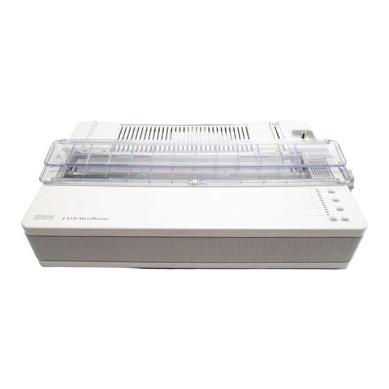
About the Printer The LA310 MultiPrinter is a wide-carriage, impact dot-matrix printer, designed for general business applications. It has flexible paper handling, and is capable of printing on continuous pinfeed paper, single sheets, multiple-part forms, and envelopes. A Pull Tractor is available as an option. The print quality is suitable for word processing in a small-to-medium computer environment. -
Page 19: Installing The Printer
Installing the Printer 1.1 Checking the Contents of the Box Unpack the LA310 MultiPrinter and make sure you have all the items shown in Figure 1–1. If any items are missing or damaged, contact your Digital office. Please complete the installation procedure in sequence. After you install the LA310 MultiPrinter, keep this guide near the printer for easy reference. -
Page 20: Box Contents
Installing the Printer 1.1 Checking the Contents of the Box Figure 1–1 Box Contents Printer Documentation Ribbon Cartridge Power Cord Serial Interface Cable 1–2 Installing the Printer... -
Page 21: Site Considerations
Installing the Printer 1.2 Site Considerations 1.2 Site Considerations The LA310 MultiPrinter can be installed in a variety of locations—for example, your office, school, or home. The LA310 MultiPrinter has the following requirements: Environmental Conditions • Install the printer in an area away from a heater or other heat source, and away from an air conditioner or strong drafts. -
Page 22: A First Look At The Printer
Installing the Printer 1.3 A First Look at the Printer 1.3 A First Look at the Printer Before installing the LA310 MultiPrinter, spend a little time familiarizing yourself with the printer. Table 1–1 A First Look at the Printer Item Number... -
Page 23: A First Look At The Printer
Installing the Printer 1.3 A First Look at the Printer Figure 1–2 A First Look at the Printer Installing the Printer 1–5... -
Page 24: Removing The Packing Material
Installing the Printer 1.3 A First Look at the Printer 1.3.1 Removing the Packing Material 1. Remove the adhesive film from the transparent covers on the front of the printer. 2. Open the front cover (see Figure 1–3), raise it, and tip it back towards the rear of the printer. -
Page 25: Installing The Power Cord
Installing the Printer 1.3 A First Look at the Printer 1.3.2 Installing the Power Cord 1. Set the power switch to OFF (0). 2. Check that the voltage of the printer (marked on the printer’s electrical data plate) matches the voltage supplied through the wall outlet. 3. -
Page 26: Installing The Ribbon Cartridge
Installing the Printer 1.3 A First Look at the Printer 1.3.3 Installing the Ribbon Cartridge 1. The ribbon cartridge is packed separately from the printer. Remove the ribbon cartridge from its wrapper. Remove the red plastic plug (provided for shipping purposes only) from the ribbon cartridge (see Figure 1–5, part 1). -
Page 27: Installing The Cartridge
Installing the Printer 1.3 A First Look at the Printer 2. Set the printhead adjustment lever to the position marked with the ribbon icon. 3. Position the ribbon cartridge on the printhead carriage, and press it downwards (see Figure 1–6). Listen for a click, then check that both sides of the cartridge are secure. -
Page 28: Removing And Replacing A Ribbon Cartridge
Installing the Printer 1.3 A First Look at the Printer 1.3.3.1 Removing and Replacing a Ribbon Cartridge To remove an old ribbon cartridge: 1. Set the power switch to OFF (0). 2. Open the front cover of the printer. Raise the front cover, and tip it back as far as you can (see Figure 1–6). -
Page 29: Testing The Printer
Installing the Printer 1.4 Testing the Printer 1.4 Testing the Printer The printer self-test allows the printer to check its operations independently. To load paper into the printer and run the self-test, perform the following steps: 1. Open the front cover, and check that the printhead adjustment lever is in position 1 (see Figure 1–7). - Page 30 Installing the Printer 1.4 Testing the Printer 2. Make sure the rollers on the bail bar are fixed in their correct grooves (see Figure 1–8), and close the front cover. The bail rollers should be fixed as follows: • In most circumstances, the left bail roller must be fixed at the groove in front of ruler position 40, and the right bail roller at the groove in front of ruler position 90.
-
Page 31: Fixing The Rollers
Installing the Printer 1.4 Testing the Printer Figure 1–8 Fixing the Rollers Installing the Printer 1–13... -
Page 32: Fixing The Rear Cover In Sloping Position
Installing the Printer 1.4 Testing the Printer 3. Close the front cover. 4. Raise the rear cover (paper support), and fix it in its sloping position with the prop (see Figure 1–9). Figure 1–9 Fixing the Rear Cover in Sloping Position 1–14 Installing the Printer... -
Page 33: Setting The Paper Selection Lever
Installing the Printer 1.4 Testing the Printer 5. Set the paper selection lever so that it points to the front of the printer (see Figure 1–10), enabling the printer to print on a cut sheet of paper. Figure 1–10 Setting the Paper Selection Lever Installing the Printer 1–15... -
Page 34: Adjusting The Paper Guides And Repositioning The
Installing the Printer 1.4 Testing the Printer 6. Fold down the upper part of the transparent cover so that you can adjust the position of the paper guides on the rear paper support. i The number 1 on the ruler behind the platen marks the position of the left margin of the printed text. -
Page 35: Inserting Paper
Installing the Printer 1.4 Testing the Printer 8. Insert a sheet of paper that is Letter size (U.S.A.) or A4 size (Europe) between the guides, and let it slide into the printer until it comes to rest behind the platen (see Figure 1–12). NOTE: Do not turn the platen knob to manually advance the paper. - Page 36 Installing the Printer 1.4 Testing the Printer The printer produces the following pattern: !"#$%&"’()*+,-./0123456789:;<=>?@ABCDEFGHIJKLMNOPQRSTUVWXYZ[\]^‘abcdefghijklmno !"#$%&"’()*+,-./0123456789:;<=>?@ABCDEFGHIJKLMNOPQRSTUVWXYZ[\]^‘abcdefghijklmnop "#$%&"’()*+,-./0123456789:;<=>?@ABCDEFGHIJKLMNOPQRSTUVWXYZ[\]^‘abcdefghijklmnopq #$%&"’()*+,-./0123456789:;<=>?@ABCDEFGHIJKLMNOPQRSTUVWXYZ[\]^‘abcdefghijklmnopqr $%&"’()*+,-./0123456789:;<=>?@ABCDEFGHIJKLMNOPQRSTUVWXYZ[\]^‘abcdefghijklmnopqrs %&"’()*+,-./0123456789:;<=>?@ABCDEFGHIJKLMNOPQRSTUVWXYZ[\]^‘abcdefghijklmnopqrst &"’()*+,-./0123456789:;<=>?@ABCDEFGHIJKLMNOPQRSTUVWXYZ[\]^‘abcdefghijklmnopqrstu "’()*+,-./0123456789:;<=>?@ABCDEFGHIJKLMNOPQRSTUVWXYZ[\]^‘abcdefghijklmnopqrstuv ’()*+,-./0123456789:;<=>?@ABCDEFGHIJKLMNOPQRSTUVWXYZ[\]^‘abcdefghijklmnopqrstuvw ()*+,-./0123456789:;<=>?@ABCDEFGHIJKLMNOPQRSTUVWXYZ[\]^‘abcdefghijklmnopqrstuvwx )*+,-./0123456789:;<=>?@ABCDEFGHIJKLMNOPQRSTUVWXYZ[\]^‘abcdefghijklmnopqrstuvwxy *+,-./0123456789:;<=>?@ABCDEFGHIJKLMNOPQRSTUVWXYZ[\]^‘abcdefghijklmnopqrstuvwxyz +,-./0123456789:;<=>?@ABCDEFGHIJKLMNOPQRSTUVWXYZ[\]^‘abcdefghijklmnopqrstuvwxyz( ,-./0123456789:;<=>?@ABCDEFGHIJKLMNOPQRSTUVWXYZ[\]^‘abcdefghijklmnopqrstuvwxyz(| -./0123456789:;<=>?@ABCDEFGHIJKLMNOPQRSTUVWXYZ[\]^‘abcdefghijklmnopqrstuvwxyz(|) ./0123456789:;<=>?@ABCDEFGHIJKLMNOPQRSTUVWXYZ[\]^‘abcdefghijklmnopqrstuvwxyz(|)~ When the bottom of the paper is detected, the sheet is automatically ejected.
-
Page 37: Connecting The Printer To A Computer System
BC19M-10. See Figure 1–13, part A. To connect the LA310 MultiPrinter to your Digital VAX system, Digital PC or PC compatible, or video terminal, through serial communication, use one of the following: •... - Page 38 Installing the Printer 1.5 Connecting the Printer to a Computer System Figure 1–13 Interface Cable 1–20 Installing the Printer...
-
Page 39: Plugging The Interface Cable Into Your Terminal
Installing the Printer 1.5 Connecting the Printer to a Computer System 2. Plug the other end of the interface cable directly into your host computer. If you use an adapter, first plug the interface cable into the appropriate adapter, and then to your host computer or video terminal (with printer port). -
Page 40: Communication Modes
Automatic port selection (the default setting). Under this setting, the printer senses which interface is active, and automatically processes data from the active port. 1.5.3 Protocols The LA310 MultiPrinter supports the following protocols (each labeled on the printer): • DEC PPL2 (labeled DEC) •... -
Page 41: If You Have Difficulties Printing A File
WARNING: Make sure that all printer covers are in place before you begin printing. NOTE: When the LA310 MultiPrinter is connected to two computer systems at the same time, the printer can accept data to print from the second port only if it has been idle for two seconds. - Page 42 Installing the Printer 1.5 Connecting the Printer to a Computer System If you have difficulties printing your files correctly, you may need to change the printer’s configuration. Some suggestions follow. 1. Check that the printer features match the host computer configuration, in particular, the communication mode.
-
Page 43: Matching Printer Protocol To Your Computer Application
1.6.1 Matching Printer Protocol on Digital VMS Systems For applications running on a Digital VMS system, select the DEC PPL2 protocol on the LA310 MultiPrinter (this is the default setting if you are using the serial port), and specify LA310 printer to your software. If the LA310 cannot be specified to your software, specify any of the following if available:... -
Page 44: Matching Printer Protocol On A Personal Computer
EPSON IBM Proprinter III or III Select the appropriate IBM driver on the application XL or IBM 4202/4203 software, and select the PP III protocol on the LA310 machines MultiPrinter (default setting if using parallel port). IBM Proprinters Select the IBM Proprinter driver on the application software, and select the PP III protocol on the LA310 MultiPrinter (default setting if using parallel port). -
Page 45: Using The Operator Control Panel
Using the Operator Control Panel 2.1 About the LA310 MultiPrinter Control Panel This chapter describes how to use the printer’s operating controls. When the cover is closed, the control panel switches perform the functions that appear above the switches. Using the Operator Control Panel 2–1... - Page 46 Using the Operator Control Panel 2.1 About the LA310 MultiPrinter Control Panel Figure 2–1 Operator Control Panel Quiet Quiet Quality NLQ1 NLQ2 Protocol Protocol PP III FX / Option Serial Port Parallel Parking Data Ready Fault Ready Pause Set-up NOTE: The functions on the control panel that appear below the switches are Set-up switches, and are explained in Chapter 4, Configuring the Printer.
-
Page 47: Printer Operating Buttons
Using the Operator Control Panel 2.1 About the LA310 MultiPrinter Control Panel 2.1.1 Printer Operating Buttons Ready/Pause Button Pressing and releasing this button toggles the printer between Pause and Ready states. In normal operation, when the printer is ready, the Ready indicator is on. -
Page 48: Printer Operating Indicators
Using the Operator Control Panel 2.1 About the LA310 MultiPrinter Control Panel Quiet/Quality Button The effect of this button depends on the state that the printer is in: • When the printer is in the Ready or busy state, pressing this button toggles the print mode between normal and quiet print modes. - Page 49 Using the Operator Control Panel 2.1 About the LA310 MultiPrinter Control Panel Port Indicators There are two port indicators: 1. Serial indicator The Serial indicator lights up when the serial port is active or selected. It may be active automatically because data is flowing through the serial port, or the serial port may have been selected in Set-up Mode.
- Page 50 Using the Operator Control Panel 2.1 About the LA310 MultiPrinter Control Panel Print Quality Indicators There are three print quality indicators, colored green on the control panel: 1. HSD This indicator is on when the print quality mode is specifically set to HSD (High Speed Draft) by yourself or by Set-up.
-
Page 51: Loading The Paper
Loading the Paper 3.1 Paper Controls The levers and controls described in this section are used for loading and positioning paper in the printer. Loading the Paper 3–1... - Page 52 Loading the Paper 3.1 Paper Controls Figure 3–1 Paper Controls 3–2 Loading the Paper...
-
Page 53: Adjustment Lever
The platen knob is used to clear paper jams. Do not use it to put paper in the correct position under the printhead (this is an automatic process on the LA310 MultiPrinter.) 4. Push Tractor The push tractor feeds single or multiple-copy continuous pinfeed stationery (see Table 3–2). -
Page 54: Loading Paper
Loading the Paper 3.2 Loading Paper 3.2 Loading Paper There are three ways to load paper for the LA310 MultiPrinter: • Load pinfeed paper using the push tractors at the back of the printer (factory default). • Hand feed single sheets from the rear of the printer carriage. -
Page 55: Loading Methods-Push Tractor (Sloping) (A1), Push Tractor (Horizontal) (A2), Single-Sheet (B), Pull Tractor (C)
Loading the Paper 3.2 Loading Paper Figure 3–2 Loading Methods—Push Tractor (sloping) (A1), Push Tractor (horizontal) (A2), Single-sheet (B), Pull Tractor (C) Loading the Paper 3–5... -
Page 56: Tractor Feeding
Loading the Paper 3.2 Loading Paper 3.2.1 Tractor Feeding 1. Set the paper selection lever towards the rear of the printer. NOTE: If you try to set the paper selection lever and paper is detected under the platen, all indicators flash simultaneously, except the Ready indicator which is lit when in the Ready state. -
Page 57: Unlocking And Adjusting The Tractor Clamps
Loading the Paper 3.2 Loading Paper 4. Unlock the two tractor clamps, and position them according to the width of the stationery that you are using. Center the paper guide on the shaft so that it is in the center of the stationery. Figure 3–4 Unlocking and Adjusting the Tractor Clamps Loading the Paper 3–7... -
Page 58: Opening The Tractor Doors And Threading Pinfeed Paper
Loading the Paper 3.2 Loading Paper 5. Open both tractor doors, and thread the pinfeed perforations onto the tractors. Make sure that the paper covers the paper sensor on the left tractor, and that at least two pins on each tractor are fed with paper. Figure 3–5 Opening the Tractor Doors and Threading Pinfeed Paper 3–8 Loading the Paper... -
Page 59: Closing The Tractor Doors And Adjusting Tension
Loading the Paper 3.2 Loading Paper 6. Close the tractor doors, and adjust the tension between the two tractors. Do not over-tension the paper so that the pinfeed holes are stretched out of shape. Figure 3–6 Closing the Tractor Doors and Adjusting Tension Loading the Paper 3–9... -
Page 60: Locking The Tractors Into Position
Loading the Paper 3.2 Loading Paper 7. When the tension has been adjusted so that the paper is taut without being overstretched, lock the tractors into position. 8. Make sure that: • the paper falls in front of the triangle marked on the the ruler. •... -
Page 61: Positioning The Rear Paper Support In Sloping Position
Loading the Paper 3.2 Loading Paper 9. Remount the rear paper support. 10. Reposition the rear paper support and the transparent covers according to the type of continuous pinfeed stationery that you are using: • If you are using multicopy stationery (original plus up to three copies), or want to use Document on Demand (see Section 3.2.1.3), fix the rear paper support in its sloping position, with the transparent covers leaning against it. -
Page 62: Positioning The Rear Paper Support Horizontally
Loading the Paper 3.2 Loading Paper 11. If you are using originals (no carbon or carbonless copies), or originals plus not more than one carbon or carbonless copy, you can position the rear paper support horizontally so that the tractor is completely covered. Close the transparent covers so that they lie flat against the paper support. -
Page 63: Viewing The Last Printed Line (Tractor-Fed Paper Only)
3.2 Loading Paper 3.2.1.2 Viewing the Last Printed Line (Tractor-Fed Paper Only) This section and Section 3.2.1.3 describe two LA310 MultiPrinter features that are available using tractor-fed paper. There are three methods to advance the paper to see the last printed line. To ease readability, place the paper support in the raised position. -
Page 64: Tearing Off Paper At The Tear Blade
Loading the Paper 3.2 Loading Paper Document on Demand works in the same way as Viewing the Last Printed Line. To use Automatic Document on Demand, you need to set Auto Advance to Selected in the GENERAL Set-up menu (the default setting is Not Selected): •... -
Page 65: Single-Sheet Loading
Loading the Paper 3.2 Loading Paper Press the Ready switch to move the paper perforation on to the tear blade. Make sure that the top part of the transparent cover is folded down, and tear off the paper. Press the Ready switch again to move the paper back to its previous position (the first printable line). -
Page 66: Raising The Rear Paper Support And Setting The Paper
Loading the Paper 3.2 Loading Paper Figure 3–11 Raising the Rear Paper Support and Setting the Paper Selection Lever 3. Set the paper selection lever towards the front of the printer. 3–16 Loading the Paper... -
Page 67: Adjusting The Paper Guides
Loading the Paper 3.2 Loading Paper 4. Set the power switch to ON (1). All indicators light up on the Control Panel. The printhead moves to the center. All indicators turn off, except for the Fault indicator. 5. Raise the upper half of the transparent cover, and fold it towards the front of the printer, so that you can access the paper guides. -
Page 68: Inserting A Sheet Of Paper
Loading the Paper 3.2 Loading Paper 7. Replace the upper half of the transparent cover so that it leans against the rear paper support. 8. Insert the sheet of paper between the guides, and let it come to rest behind the platen. -
Page 69: Parking Continous Stationery
Loading the Paper 3.2 Loading Paper 3.2.3 Parking Continous Stationery You can switch from rear loading continous stationery to single-sheet loading even if you already have continuous pinfeed stationery loaded in the printer. If you have stationery already loaded, you must tear off any completed forms. To switch from rear loading to single-sheet loading (this switching is called the Park function): 1. -
Page 70: Adjusting The Printhead For Paper Thickness
Loading the Paper 3.3 Adjusting the Printhead for Paper Thickness 3.3 Adjusting the Printhead for Paper Thickness You must adjust the printhead to the setting appropriate for the stationery you are using. You adjust the printhead by using the printhead adjustment lever (see Figure 3–14). -
Page 71: Adjusting The Printhead For Paper Thickness
Loading the Paper 3.3 Adjusting the Printhead for Paper Thickness Figure 3–14 Adjusting the Printhead for Paper Thickness Loading the Paper 3–21... -
Page 72: Adjusting For Paper Width
Loading the Paper 3.4 Adjusting for Paper Width 3.4 Adjusting for Paper Width Paper must fall in front of the mark on the ruler (the paper sensor). The default left margin is numbered 1 on the ruler. The only way to change the left margin is by sending the appropriate protocol-specific software sequence. -
Page 73: Bail Bar Settings
Loading the Paper 3.4 Adjusting for Paper Width Figure 3–15 Bail Bar Settings Loading the Paper 3–23... -
Page 74: Error Conditions During Operation
Loading the Paper 3.5 Error Conditions During Operation 3.5 Error Conditions During Operation When the printer detects an error condition, the following applies: • Paper-out conditions at power-up: At power-up in Push Tractor mode, if paper is not loaded under the platen and is not installed in the push tractors, the printer beeps and the Fault indicator lights. - Page 75 Loading the Paper 3.5 Error Conditions During Operation • Moving the paper selection lever when paper is in the printing position: If you move the paper selection lever in an attempt to toggle from one loading method to another (for example, from the Push Tractor method to the Single-sheet method), when paper is in the printing position, all indicators blink simultaneously, with the exception of the Ready indicator.
-
Page 77: Configuring The Printer
Configuring the Printer 4.1 What is Configuration? This chapter describes how to set up or configure the LA310 MultiPrinter, so that the printer and your computer system can communicate correctly with each other, and so that the printer suits your requirements. -
Page 78: Positioning Of Red Triangle Against Main Menu Entry
Configuring the Printer 4.2 Structure of the Set-up Menus At each main menu or submenu, the item that was selected prior to entering this menu is printed in bold type, and the red triangle on the printhead guide is automatically positioned underneath the item. Figure 4–1 provides an example of the location of the red triangle on the printhead plastic guide against the main menu entry COMMUNICATIONS. -
Page 79: Set-Up Mode Buttons And Indicators
Configuring the Printer 4.3 Set-up Mode Buttons and Indicators 4.3 Set-up Mode Buttons and Indicators There are five buttons on the control panel that perform functions in Set-up mode. Normal mode Set-up mode function function Set-up function Ready Set-up Enter/Exit Set-up mode Quiet/Quality Next Item LF/Protocol... -
Page 80: Printing The Printer's Current Configuration
1. At the Set-up directory, the red triangle points to PRINT, which is the initial default entry. Select PRINT by pressing The printer then prints its current settings. The factory-set configuration for the LA310 MultiPrinter begins printing as follows: 4–4 Configuring the Printer... -
Page 81: Changing The Printer's Configuration
Configuring the Printer 4.3 Set-up Mode Buttons and Indicators 4.3.3 Changing the Printer’s Configuration At each menu or submenu beyond the Set-up menu, the item that was selected prior to entering this menu is printed in bold type, and the red triangle on the printhead is automatically positioned underneath the item. - Page 82 Configuring the Printer 4.3 Set-up Mode Buttons and Indicators 3. As the Error Beep setting is not listed, press as many times as necessary to move to the final line of the menu, which is displayed as follows: 4. Press to move to the Error Beep setting, and press to select it.
-
Page 83: Saving New Values And Exiting Set-Up Mode
Configuring the Printer 4.3 Set-up Mode Buttons and Indicators The entry ONE BEEP is bolded as it is the default setting. 5. Press to move to the THREE BEEPS setting, and press to select it. The selected item is underlined, the printer enters the GENERAL menu, and the red triangle points to the ERROR BEEP submenu: 4.3.4 Saving New Values and Exiting Set-up Mode Pressing the Set-up switch once while in Set-up mode stores your set-up... -
Page 84: Optional Emulation Selection Set-Up
Configuring the Printer 4.3 Set-up Mode Buttons and Indicators 4.3.6 Optional Emulation Selection Set-up Optional emulation can be the resident EPSON FX-1050 emulation, or emulation provided by a cartridge installed in the printer. To determine which optional emulation you want to use, you must define the emulation using optional emulation set-up. -
Page 85: Error Conditions In Set-Up Mode
Configuring the Printer 4.3 Set-up Mode Buttons and Indicators 4.3.7 Error Conditions in Set-up Mode When the printer detects that there is no paper, or that the printer cover is open, the following applies: 1. Paper-out condition in Set-up mode: •... -
Page 86: Summary Of Set-Up Features
Configuring the Printer 4.4 Summary of Set-up Features 4.4 Summary of Set-up Features The following tables list the Set-up menu features and reflect the Set-up architecture. In the Menu Items column, the main menu items are bolded. In the Parameter column, the default setting of each parameter is bolded. This is the factory setting and is automatically reset when the FACTORY DFLT feature is selected, with the exception of the Optional Emulation Selection. -
Page 87: Communications Menu
Configuring the Printer 4.4 Summary of Set-up Features Table 4–3 PROTOCOL SELECTION menu Menu Item Parameter PORT DEPENDENT, DEC PPL2, IBM PP III, EPSON FX-1050 or Optional Emulation PORT DEPENDENT SERIAL PORT DEC PPL2, IBM PP III, EPSON FX-1050 or Optional Emulation PARALLEL PORT DEC PPL2, IBM PP III, EPSON FX-1050 or Optional Emulation... - Page 88 Configuring the Printer 4.4 Summary of Set-up Features Table 4–5 DEC PPL2 Menu Menu Item Parameter CHARACTER SETS G0 CHAR SET ASCII, BRITISH, DEC FINNISH, FRENCH, DEC FRENCH- CAN, GERMAN, ISO ITALIAN, JIS ROMAN, DEC NORW/DAN, ISO SPANISH, DEC SWEDISH, NORWEG/DANISH, DEC DUTCH, DEC SWISS, DEC PORTUGUESE, LEGAL, DEC 7 HEBREW, DEC HEBREW SUPP, DEC GREEK SUPP, DEC 7 TURKISH, DEC 8 TURKISH, JIS KATAKANA, DEC...
- Page 89 Configuring the Printer 4.4 Summary of Set-up Features Table 4–6 IBM PP III Menu Menu Item Parameter CHARACTER SETS C-SET 1/2 C-SET 1 (selects Character Set 1), C-SET 2 (selects Character Set 2) NATIONAL SET USA (437), MULTI (850), PORTUG (860), NORWAY (865), SPAIN (220), GREECE (210), CAN-FR (863), TURKEY (857), HEBREW (862), Not Present , Cartridge character sets (labeled...
-
Page 90: Optional Emulation Menu
Configuring the Printer 4.4 Summary of Set-up Features Table 4–7 Epson FX-1050 Menu Menu Item Parameter CHARACTER SETS GRAPHIC/ITALIC GRAPHIC 1 , GRAPHIC 2 , ITALIC 1 , ITALIC 2 NATIONAL ASCII USA, FRANCE, GERMANY, U.K., DENMARK 1, SWEDEN, ITALY, SPAIN 1, JAPAN, NORWAY, DENMARK 2, SPAIN 2, LATIN AMERICA, Not Present , Cartridge character sets (labeled EXT) -
Page 91: Maintaining The Printer
Maintaining the Printer 5.1 General Maintenance The printer does not need preventive maintenance. The casing of the printer and the platen will need cleaning from time to time. Digital’s computer-accessories catalog, DECdirect, lists suitable cleaners for these tasks. Always use the cleaners in accordance with the instructions on the cleaners. Paper Select the correct kind of paper for the job. -
Page 92: Power-Related Problems
Maintaining the Printer 5.2 Correcting Simple Problems How to Use This Section 1. Find the category in which your problem occurs. The problem categories are: Power-related Problems No Printout Operation-related Problems Print-related Problems Ribbon or Carriage-related Problems For example, if the print appears very light on the paper, look at Section 5.2.4, Print-related Problems. -
Page 93: No Printout
Maintaining the Printer 5.2 Correcting Simple Problems • Ready indicator is flashing; Fault indicator is flashing (1 second period), and does not respond when the Ready switch is pressed. Is the access cover fitted and seated correctly? Closing it and pressing the Ready switch should light the Ready indicator. -
Page 94: Operation-Related Problems
The LA310 MultiPrinter stops printing; Fault indicator is On. This is an "out of paper" response. Load paper; if the Ready indicator is flashing, press the Ready switch. The LA310 MultiPrinter should resume printing. Make sure that the paper is not torn or otherwise damaged. - Page 95 Maintaining the Printer 5.2 Correcting Simple Problems • No reverse paper feed. Make sure that you are not at the end of the paper. Make sure that the printer is in the pause state. Make sure that the paper is not damaged. Make sure that you have set the printer for tractor feeding.
-
Page 96: Print-Related Problems
Maintaining the Printer 5.2 Correcting Simple Problems • Narrow paper hits bail bar on top of form, or jams. Refer to Section 3.4. Check the paper width setting in Set-up. Adjust the bail rollers. • Cut sheet paper is skewed. Adjust cut sheet paper guides. - Page 97 Maintaining the Printer 5.2 Correcting Simple Problems Make sure that the platen can rotate freely by moving the platen knob. The platen can only rotate freely when the printer is in the Pause state. Make sure that the paper stack is free. •...
-
Page 98: Ribbon Or Carriage-Related Problems
Maintaining the Printer 5.2 Correcting Simple Problems • Printer does not stop when out of paper. Printer circuits do not detect that there is no paper. Examine the paper pathway. Remove any obstructions. Press the Ready switch when the paper pathway is cleared. •... -
Page 99: Service
If you cannot correct a problem with the printer, contact your local Digital office. 5.4 Digital Equipment Corporation Services Digital Equipment Corporation provides a wide range of maintenance programs that cover small systems, terminals, and printers. These include on-site, carry- in, and mail-in maintenance services. You can use these programs to select a plan that meets your service needs, from complete Digital support to self-maintenance. - Page 100 Maintaining the Printer 5.5 Calling the Service Center Be ready to answer questions Summarize the problem. Make a note of: when you call. • What you were doing when the printer failed • Any indications on the control panel • Any strange noises Stay by the printer/host system if possible;...
-
Page 101: A.1 Specifications
Reference Information A.1 Specifications Printer Specifications Feature Range Printing Method: Impact Dot Matrix, 9 pin Protocols: Digital’s Conformance Level-2 (for sixel graphics) IBM Proprinter III (4201/4202-III) Epson FX-1050 Interfaces: Serial, via 6 pin DECconnect type connector Parallel, via 36 pin Centronics type connector Selectable Baud 150, 300, 600, 1200 Rates:... - Page 102 Reference Information A.1 Specifications Feature Range Average Print Speeds: Print Speed 300 CPS Draft 240 CPS NLQ1 55 CPS NLQ2 55 CPS Throughput Performance: Standard ECMA 132, Print Speed (pages per hour) continuous form Draft Letter 271 pph HSD Letter 298 pph NLQ1/2 Letter 97 pph...
- Page 103 Reference Information A.1 Specifications Feature Range Character Sets: DEC PPL2 ASCII DEC Supplemental DEC VT100 Special Graphics DEC Technical ISO Latin-1 Supplemental National Replacement Character (NRC) Sets: British DEC Finnish French DEC French/Canadian German ISO Italian JIS Roman DEC Norway/Denmark ISO Spanish DEC Swedish Norway/Denmark...
- Page 104 Reference Information A.1 Specifications Feature Range Character Sets: IBM PP III and Epson FX USA (Code Page 437) Multilingual (Code Page 850) Portugal (Code Page 860) Norway (Code Page 865) National Spain (Code Page 220) Greece (Code Page 210) Canada - French (Code Page 863) Hebrew (code Page 862) Turkey (Code Page 857) Input Buffer:...
- Page 105 Reference Information A.1 Specifications Feature Range Dimensions: Width= 605 mm, Depth = 378 mm, Height = 110 mm. Weight: 10 kg Power Requirements: 120 V @ 1.6 Amps, 50/60 Hz, 50 W 220 V @ 1.0 Amps, 50/60 Hz, 50 W 240 V @ 1.0 Amps, 50/60 Hz, 50 W Noise Level: —Average Acoustic...
- Page 106 Reference Information A.1 Specifications Paper Specifications Feature Range Paper Types: Pinfeed (tractor media) Single sheets Up to 4 part forms (with no pull tractor) Envelopes Continuous Paper (Tractor Media): Single part continuous paper up to 16" (40.6 cm) wide including perforations is supported. The allowable weight for these forms is 56 to 90 g/m²...
-
Page 107: A.2 Printer Accessories
Reference Information A.2 Printer Accessories A.2 Printer Accessories Description Part Number Ribbon Cartridges Black Ribbon Cartridges (six in a box) LA31R-06 Optional Cartridge ISO Latin-2/Cyrillic character sets LA31X-CA Cables Serial Data Cable BC16E-10 Parallel Data Cable BC-19M-10 Shielded Serial Data Cable DD-16E-10 Accessories Pull Tractor... - Page 108 MicroVAX 2000 BC16E DECserver 200/DL (DSRVB-BA) BC16E VT300-Series BC16E CPU DEC423 ports BC16E VT 420 BC16E The BC16E cable is included with the LA310 MultiPrinter. If the BC16E cable is listed on its own, no adapter is required. A–8 Reference Information...
- Page 109 25-Pin Female Rainbow H8571-D and BC16E 25-Pin Female Parallel Port DECpc and DECstation machines BC19M-10 The BC16E cable is included with the LA310 MultiPrinter. If the BC16E cable is listed on its own, no adapter is required. Reference Information A–9...
-
Page 111: B.1 Types Of Cartridges
DEC PPL2 mode). All cartridges are optional. Only one cartridge can be used at a time. B.1 Types of Cartridges There are three types of cartridges supported by the LA310 MultiPrinter: 1. Font cartridges 2. Character set cartridges 3. -
Page 112: B.1.1 Font Cartridges
A font cartridge provides one or two typestyles in addition to the NLQ2 style that is resident in the LA310. Most of the resident character sets are covered with these typestyles. See Section B.3 to check the contents of the cartridge installed. -
Page 113: Inserting The Cartridge
Using Font and Character Set Cartridges B.2 Installing a Cartridge Figure B–1 Inserting the cartridge Using Font and Character Set Cartridges B–3... -
Page 114: B.3 Checking The Contents Of The Cartridge
Using Font and Character Set Cartridges B.3 Checking the Contents of the Cartridge B.3 Checking the Contents of the Cartridge When you enter Set-up mode with a cartridge installed, the printer lists the contents of the cartridge, before you can make any selection. In DEC PPL2 mode, the data needed for the software selection of the character sets or the typestyles is also provided. -
Page 115: C.1 User Form Length Mode
You can set the form length in one of two ways: automatic or manual. C.1.1 Setting User Form Length Automatically To set a form length automatically, the LA310 MultiPrinter measures a sample form. The sample form must be fed in single-sheet mode. Even if you plan to use continuous stationery in the printer, you must feed a single sheet of this stationery into the printer in order for the printer to measure it. -
Page 116: C.1.2 Setting User Form Length Manually
Defining Form Settings C.1 User Form Length Mode b. Press the FF button. The printer aligns the top of the form with the top of the printhead plastic guide. Press the FF button again. The printer measures the length of the form automatically. The form is then ejected. -
Page 117: C.1.3 Checking The Form Length Value Store
Defining Form Settings C.1 User Form Length Mode All indicators switch off for approximately one second, and the printer resets automatically to normal operation. In single-sheet mode, the current sheet is ejected before the printer returns to normal operation. C.1.3 Checking the Form Length Value Store As the form length setting is set automatically, you may want to check its value. -
Page 118: Top Of Form Setting Buttons
Defining Form Settings C.2 Top of Form Setting C.2 Top of Form Setting The Top of Form setting allows you to adjust the position of the printed text on the page within a range of ±0.25 inches, with no impact on tear-off operations, and can be set at any line on the form. - Page 119 Defining Form Settings C.2 Top of Form Setting 5. Press FF (SET T.O.F). The following line is printed at the current line first column: HHHHHHHH and the paper is advanced to enable you to read the printed line. The printer disables the LINE and SET T.O.F. keys. "...
-
Page 121: D.1 Entering Control Rendition Mode
While printing control characters, each control character is not active but is printed by the LA310 MultiPrinter, with the exception of: •... - Page 123 Internal Console This appendix provides information on operations that use buttons on the internal console. Internal Console E–1...
-
Page 124: E–1 Internal Console
Internal Console Figure E–1 Internal Console PRINT TEST LINE DUMP TOP OF FORM TOP OF FORM TOP OF FORM FAULT SET-UP FORM LENGTH SAVE SET TOP OF FORM The following modes can be initiated at power-up with the front cover open, by pressing a button on the internal console: •... - Page 125 Internal Console Pressing the T.O.F key at power-up causes the printer to enter the Top of Form Setting mode as described in Section C.2, which also provides the meaning of each key on the internal console in this mode. • User Form Length mode Pressing the FORM LENGTH key at power-up causes the printer to enter the User Form Length mode, as described in Section C.1.
- Page 127 Horizontal Line Adjustment The LA310 MultiPrinter processes text printing in bidirectional mode by default. It also processes NLQ1 and NLQ2 print modes in two passes in bidirectional mode (provided that the set-up feature NLQ DIRECTION is set to BIDIRECTIONAL). The horizontal line adjustment is optimized before the printer leaves the factory, so that the two passes are horizontally aligned.
-
Page 128: Horizontal Line Adjustment Pattern
Horizontal Line Adjustment Figure F–1 Horizontal Line Adjustment Pattern LEVEL 1 LEVEL 2 LEVEL 3 LEVEL 4 LEVEL 5 LEVEL 6 LEVEL 7 Selection : 4 The horizontal line adjustment allows you to select one of the seven possible settings that are given in the pattern. The last line of the printed pattern shows the pattern that was selected last. - Page 129 Horizontal Line Adjustment 6. To leave this mode, switch the power to OFF (0). You can switch the power off at any time during the printhead test. Horizontal Line Adjustment F–3...
-
Page 131: G.1 Set-Up Menu Structure
Set-up Menu Structure G.1 Set-up Menu Structure Set-up mode enables you to customize the printer for your specific use. This appendix shows the structure of the Set-up menus, and can be used in conjunction with Chapter 4. In the following figures, bolded items are the default settings. - Page 132 Set-up Menu Structure G.1 Set-up Menu Structure General Main Menu Form Paper Print Typestyle Backward Auto Bottom Input Error Paper Length Width Quality Direction Motion Advance of form Buffer Beep Forced HSD 3" Bidirectional Not Selected 16 k Selected Forced NLQ1 3.5"...
- Page 133 Set-up Menu Structure G.1 Set-up Menu Structure Protocol Selection Main Menu PORT-DEPENDENT DEC PPL2 IBM PP III EPSON FX-1050 OR CARD EMULATION DEC PPL2 IBM PP III EPSON FX-1050 Protocol Protocol or Card Emulation Selected Selected Selected SERIAL PORT PARALLEL PORT DEC PPL2 DEC PPL2 IBM PP III...
- Page 134 Set-up Menu Structure G.1 Set-up Menu Structure Communications Main Menu PORT SELECTION SERIAL COMMUNICATIONS Automatic Serial Port Parallel Port BAUD DATA BUFFER MONITOR DISCONNECT RATE FORMAT CONTROL ON FAULT Xon/Xoff Not Selected Drop DTR Pulse DTR 1200 Break Signal 7-Space 2400 7-Mark 4800...
- Page 135 Set-up Menu Structure G.1 Set-up Menu Structure DEC PPL2 Main Menu Character Horizontal Vertical Printer Disconnect Init. Auto Answerback Auto Sets Pitch Pitch on EOT Report Answerback on ENQ Wrap on CR on LF User Not Selected Not Selected Not Selected Not Selected Char Pref.
- Page 136 Set-up Menu Structure G.1 Set-up Menu Structure IBM PP III Main Menu Character Horizontal Vertical 12 cpi Slashed Sets Pitch Pitch /Cond. on CR on LF C-Set National 12 cpi Not Selected 20 cpi Selected 8.55 Normal 0 Not Selected 72/7 17.1 C-Set 1...
- Page 137 Set-up Menu Structure G.1 Set-up Menu Structure Epson FX-1050 Main Menu Character Horizontal Vertical Slashed Sets Pitch Pitch on CR Graphic National Code Normal 0 Not Selected /Italic ASCII Page Slashed 0 Selected 8.55 Graphic 1 17.1 72/7 Graphic 2 lpcm Italic 1 Proport.
-
Page 139: Positioning Controls
DEC PPL2 Quick Reference This appendix contains basic information on the DEC PPL2 commands that are supported in the LA310 MultiPrinter. It also contains the character set code tables supported by the LA310 MultiPrinter in the DEC PPL2 protocol. The commands are listed by function in the following order:... -
Page 140: H–1 Conventions
DEC PPL2 Quick Reference Table H–1 Conventions Escape (1/11), introduces an escape sequence Control Sequence Introducer (9/11), introduces a control sequence. CSI can also be represented by the equivalent escape sequence ESC [ (1/11 5/11). Device Control String (9/0), introduces a device control string. DCS can also be represented by the equivalent escape sequence ESC P (1/11 5/0). -
Page 141: H–2 Positioning Controls
DEC PPL2 Quick Reference Table H–2 Positioning Controls DECCAHT Clear All Horizontal ESC 2 Tabs DECCAVT Clear All Vertical Tabs ESC 4 CSI Pn ;...; Pn u DECSHTS Set Horizontal Tab Stops Pn = tab stop position CSI Pn ;...; Pn v DECSVTS Set Vertical Tab Stops Pn = tab stop position... -
Page 142: Type Size And Spacing, Managing Implicit Cursor Motion
DEC PPL2 Quick Reference Table H–4 Type size and spacing, managing implicit cursor motion DECAWM Autowrap Mode CSI ? 7 h Set autowrap mode CSI ? 7 l Reset autowrap mode DECCRNLM Carriage CSI ? 40 h CR acts as New Line CSI ? 40 l Return/ New CR acts as Carriage Return... -
Page 143: Font Management And Attribute Selection
DEC PPL2 Quick Reference Table H–5 Font management and attribute selection Select Graphic Rendition CSI Ps m Ps = 10: Built in Typestyle - Selecting Fonts Ps = 11–19: Cartridge Typestyle or Downloaded font Select Graphic Rendition CSI Ps ; . . . ; Ps m Ps = 0: Turn off all attributes - Selecting Attributes Ps = 1: Bold on... -
Page 144: Selecting Character Sets
DEC PPL2 Quick Reference Table H–7 Selecting character sets ASCEF Announce Subset ESC SP L ASCII in G0 and GL. of Code Extension ISO Latin-1 Supplemental in G1 and Facilities ESC SP M Same as ESC SP L ESC SP N ASCII in G0 and GL. -
Page 145: Designating And Invoking Character Sets
DEC PPL2 Quick Reference Figure H–1 Designating and Invoking Character Sets Invoking or LS2 LS1R "Invoking" Sequences Locking Shift, or LS3 Single Shift, LS2R or Announcers LS3R Announcer Sequences "Designating" Sequences (SCS) or Announcers Selecting 94-Char 96-Char Graphic Graphic Repertory Repertory DECAUPSS User... -
Page 146: Character Sets Power-Up Settings
DEC PPL2 Quick Reference Table H–8 Character Sets Power-up Settings Character Set Power-up Setting G0 CHAR SET Defined by Set-up feature G0 CHAR SET ASCII G2 and G3 User Preference Character Set User Preference Supplemental Defined by Set-up feature USER PREF SET Table H–9 Reports Device CSI c... -
Page 147: Miscellaneous
CSI 3 l Print text normally DECASFC Automatic Sheet CSI Ps ! v Performs Conditional Sheet Feed (The Feeder Control LA310 MultiPrinter has no sheet feeder) CSI ? 41 h DECUPM Unidirectional Print Set unidirectional print mode Mode CSI ? 41 l... -
Page 148: Scs Final Characters
DEC PPL2 Quick Reference Table H–10 (Cont.) Miscellaneous DECTC1/ C1 Receive ESC SP 6 Process 7-bit, drop 8th bit ESC SP 7 DECAC1 Process 7-bit and 8-bit DECLANS Load DCS Ps v Ps = 1: load message, do not store in D...D ST Answerback NVRAM... - Page 149 DEC PPL2 Quick Reference Table H–11 (Cont.) SCS Final Characters F Designator Character Set Characters Code DEC Swiss 3/13 Norwegian/Danish ‘ DEC Supplemental 2/5, 3/5 DEC Technical > 3/14 DEC Special Graphics DEC Portuguese 2/5, 3/6 7-Bit Turkish 2/5, 3/2 DEC 8-Bit Turkish Supplemental 2/5, 3/0 DEC 8-Bit Greek Supplemental...
-
Page 150: Standard 8-Bit Code Table (Left Half)
DEC PPL2 Quick Reference Figure H–2 Standard 8-bit Code Table (Left Half) Standard Left C0 Control Set Graphics Left (GL) Column (XON) " (XOFF) & < > ASCII Graphic Character Set LEGEND Column/Row Octal Decimal MLO-003973 H–12 DEC PPL2 Quick Reference... -
Page 151: Standard 8-Bit Code Table (Right Half)
DEC PPL2 Quick Reference Figure H–3 Standard 8-bit Code Table (Right Half) Standard Right C1 Control Set Graphics Right (GR) Column µ DEC Supplemental Graphic Character Set LEGEND 12/1 Column/Row Octal Decimal MLO-003974 DEC PPL2 Quick Reference H–13... -
Page 152: National Replacement Character Sets
DEC PPL2 Quick Reference The following tables provide a list of positions from the National Replacement Character (NRC) sets which differ from the U.S. ASCII Character Set. All other positions of these NRC sets are the same as in the U.S. ASCII character set. Table H–12 National Replacement Character sets National Replacement Character Sets Location... - Page 153 DEC PPL2 Quick Reference Table H–12 (Cont.) National Replacement Character sets National Replacement Character Sets Location Norwegian- Norwegian- ASCII Danish Spanish Swedish Danish Dutch Swiss Portuguese £ £ ù Ä § É à 5/11 Æ ¡ Ä Æ ÿ é Ã...
-
Page 154: Dec Special Graphics Character Set
DEC PPL2 Quick Reference Figure H–4 DEC Special Graphics Character Set DEC Special Graphics Character Set GL GR GL GR GL GR GL GR GL GR GL GR Column 360 Row SCAN 3 SCAN 5 " SCAN 7 SCAN 9 &... -
Page 155: Dec Technical Character Set
DEC PPL2 Quick Reference Figure H–5 DEC Technical Character Set DEC Technical Character Set GL GR GL GR GL GR GL GR GL GR GL GR Column 360 Row Π π Ψ α ψ β ρ Σ χ σ δ τ... -
Page 156: Iso Latin-1 Supplemental Character Set
DEC PPL2 Quick Reference Figure H–6 ISO Latin-1 Supplemental Character Set ISO Latin-1 Supplemental Character Set GL GR GL GR GL GR GL GR GL GR GL GR Column 360 Row NBSP LEGEND 12/1 Column/Row Octal Decimal MLO-004000 H–18 DEC PPL2 Quick Reference... -
Page 157: Legal Character Set
DEC PPL2 Quick Reference Figure H–7 Legal Character Set Legal GL GR GL GR GL GR GL GR GL GR GL GR Column 360 Row " & < > LEGEND GL GR 12/1 Column/Row Octal Decimal MLO-003982 DEC PPL2 Quick Reference H–19... -
Page 158: Dec 7-Bit Hebrew Character Set
DEC PPL2 Quick Reference Figure H–8 DEC 7-bit Hebrew Character Set DEC 7-Bit Hebrew Character Set GL GR GL GR GL GR GL GR GL GR GL GR Column 360 Row " & < > LEGEND GL GR 12/1 Column/Row Octal Decimal MLO-004001... -
Page 159: Dec Hebrew Supplemental Character Set
DEC PPL2 Quick Reference Figure H–9 DEC Hebrew Supplemental Character Set DEC Hebrew Supplemental Character Set GL GR GL GR GL GR GL GR GL GR GL GR Column 360 Row µ LEGEND GL GR 12/1 Column/Row Octal Decimal MLO-004002 DEC PPL2 Quick Reference H–21... -
Page 160: Iso Latin-Hebrew Supplemental Character Set
DEC PPL2 Quick Reference Figure H–10 ISO Latin-Hebrew Supplemental Character Set ISO Latin-Hebrew Supplemental Character Set GL GR GL GR GL GR GL GR GL GR GL GR Column 360 Row NBSP µ LEGEND 12/1 Column/Row Octal Decimal MLO-004003 H–22 DEC PPL2 Quick Reference... -
Page 161: Iso Latin-Greek Supplemental Character Set
DEC PPL2 Quick Reference Figure H–11 ISO Latin-Greek Supplemental Character Set ISO Latin-Greek Supplemental Character Set GL GR GL GR GL GR GL GR GL GR GL GR Column 360 Row ι Π υ π NBSP Α Ρ α ρ Β... -
Page 162: Dec Greek Supplemental Character Set
DEC PPL2 Quick Reference Figure H–12 DEC Greek Supplemental Character Set DEC Greek Supplemental Character Set GL GR GL GR GL GR GL GR GL GR GL GR Column 360 Row ι υ Α Π α π Β Ρ β ρ... -
Page 163: Iso Latin-5 Supplemental Character Set
DEC PPL2 Quick Reference Figure H–13 ISO Latin-5 Supplemental Character Set ISO Latin-5 Supplemental Character Set GL GR GL GR GL GR GL GR GL GR GL GR Column 360 Row NBSP β LEGEND 12/1 Column/Row Octal Decimal MLO-006611 DEC PPL2 Quick Reference H–25... -
Page 164: Dec Turkish 7-Bit Character Set
DEC PPL2 Quick Reference Figure H–14 DEC Turkish 7-bit Character Set DEC Turkish 7-bit Character Set GL GR GL GR GL GR GL GR GL GR GL GR Column 360 Row " < > LEGEND GL GR 12/1 Column/Row Octal Decimal MLO-006605 H–26 DEC PPL2 Quick Reference... -
Page 165: Dec Turkish 8-Bit Supplemental Character Set
DEC PPL2 Quick Reference Figure H–15 DEC Turkish 8-bit Supplemental Character Set DEC Turkish 8-bit Supplemental Character Set GL GR GL GR GL GR GL GR GL GR GL GR Column 360 Row µ β LEGEND GL GR 12/1 Column/Row Octal Decimal MLO-006606... -
Page 166: Iso Latin-Cyrillic Supplemental Character Set
DEC PPL2 Quick Reference Figure H–16 ISO Latin-Cyrillic Supplemental Character Set ISO Latin-Cyrillic Supplemental Character Set GL GR GL GR GL GR GL GR GL GR GL GR Column 360 Row Α Ρ ρ Ν NBSP δ Β Τ Β Τ... -
Page 167: Iso Latin-2 Supplemental Character Set
DEC PPL2 Quick Reference Figure H–17 ISO Latin-2 Supplemental Character Set ISO Latin-2 Supplemental Character Set GL GR GL GR GL GR GL GR GL GR GL GR Column 360 Row NBSP LEGEND GL GR 12/1 Column/Row Octal Decimal MLO-006608 DEC PPL2 Quick Reference H–29... -
Page 168: Jis Katakana Character Set
DEC PPL2 Quick Reference Figure H–18 JIS Katakana Character Set JIS Katakana GL GR GL GR GL GR GL GR GL GR GL GR Column 360 Row LEGEND GL GR 12/1 Column/Row Octal Decimal MLO-003983 H–30 DEC PPL2 Quick Reference... -
Page 169: I–1 Conventions
IBM Proprinter III Quick Reference This appendix contains basic information on the Proprinter III Emulation commands supported in the LA310 MultiPrinter. It also contains the character set code tables supported by the LA310 MultiPrinter in Proprinter III emulation mode. In addition Table I–9 provides a list of differences between the LA310 MultiPrinter in Proprinter III emulation mode, and the IBM Proprinter III machine. -
Page 170: Terminal Management
IBM Proprinter III Quick Reference Table I–2 Control Characters Location Control Character in Character Set 1 in Character Set 2 Description 0/0 or 8/0 Null 0/7 or 8/7 Beeper 0/8 or 8/8 Backspace 0/9 or 8/9 Horizontal Tab 0/10 or 8/10 0/10 Line Feed 0/11 or 8/11... -
Page 171: Vertical Form Handling
IBM Proprinter III Quick Reference Table I–3 (Cont.) Terminal Management Escape Sequence Description ESC % @ Return to DEC PPL2 mode ESC @ Reset Printer ESC Q Deselect Printer ESC [ ! p Reset Printer to DEC PPL2 mode ESC [ K n1 n2 init id P1 P2 Set Initial Condition. -
Page 172: Horizontal Form Handling And Printing Modes
IBM Proprinter III Quick Reference Table I–5 Horizontal Form Handling and Printing Modes Escape Sequence Description ESC : Set Horizontal Spacing to 12 CPI ESC - Pn Continuous Underline Printing Pn = 0/1 : set Underline Printing, Pn = 0/0 : cancel Underline Printing ESC _ Pn Continuous Overscore Printing Pn = 0/1 : set Overscore Printing,... -
Page 173: Print-Mode Priority Chart
IBM Proprinter III Quick Reference Table I–5 (Cont.) Horizontal Form Handling and Printing Modes Escape Sequence Description ESC W Pn Continuous Double-Wide Printing = 0/1 : set Double-Wide printing, = 0/0 : cancel Double-Wide printing ESC SO Double-Wide Printing by Line. This command is cancelled by ESC X P1 P2 Set Horizontal Margins... -
Page 174: Graphics Modes
IBM Proprinter III Quick Reference Table I–6 (Cont.) Print-Mode Priority Chart Print-Mode Combinations Resulting Mode Double-Strike, Draft NLQ1 Double-Strike, NLQ1 NLQ1 Super/Subscript, NLQ1 or NLQ2 Super/Subscript, Draft Block Graphics (176-223,244), Overscore or Block Graphics, no Over/Underline Underline Double-High, Draft, Emphasized Double-High, NLQ1, Emphasized Double-High, 12 cpi Double-High, 10 cpi... -
Page 175: Character Set Selection
The characters in columns 0, and 1 are not printed. The control characters as specified in the third column of Table I–2 are applicable. Table I–9 Emulation Differences between the LA310 MultiPrinter in IBM PP III mode and the IBM Proprinter III/III-XL... - Page 176 IBM Proprinter III Quick Reference Table I–9 (Cont.) Emulation Differences between the LA310 MultiPrinter in IBM PP III mode and the IBM Proprinter III/III-XL LA310 MultiPrinter IBM Proprinter III/III-XL High Speed Draft print density (HSD) Applicable if set by the front panel or setup.
- Page 177 IBM Proprinter III Quick Reference Table I–9 (Cont.) Emulation Differences between the LA310 MultiPrinter in IBM PP III mode and the IBM Proprinter III/III-XL LA310 MultiPrinter IBM Proprinter III/III-XL Underlining Full Cell characters Full Cell characters cannot be underlined in any Full Cell characters may be underlined in printing mode.
-
Page 178: All Characters Set, All Code-Pages, Left Side
IBM Proprinter III Quick Reference Figure I–1 All Characters Set, All Code-pages, Left Side IBM All Character Set (1) Column " & < > LEGEND Column/Row Octal Decimal MLO-004008 I–10 IBM Proprinter III Quick Reference... -
Page 179: All Characters Set, Code-Page 437 U.s.a. , Right Side
IBM Proprinter III Quick Reference Figure I–2 All Characters Set, Code-page 437 U.S.A. , Right Side IBM All Character Set (1B) Column 360 Row α β Γ Π Σ σ µ τ Φ Θ Ω δ φ ε LEGEND 12/1 Column/Row Octal Decimal... -
Page 180: All Characters Set, Code-Page 850 Multilingual, Right Side
IBM Proprinter III Quick Reference Figure I–3 All Characters Set, Code-page 850 Multilingual, Right Side Code Page 850 (Multilingual) Column 360 Row β ι µ LEGEND 12/1 Column/Row Octal Decimal MLO-007427 I–12 IBM Proprinter III Quick Reference... -
Page 181: All Characters Set, Code-Page 210 Right Side
IBM Proprinter III Quick Reference Figure I–4 All Characters Set, Code-page 210 Right Side Code Page 210 (Greece) Column 360 Row Α Ρ ι ω Ω Β Σ κ α Γ Τ λ ε ∆ Υ µ η Ε Φ ν... -
Page 182: All Characters Set, Code-Page 220 Right Side
IBM Proprinter III Quick Reference Figure I–5 All Characters Set, Code-page 220 Right Side Code Page 220 (National Spain) Column ∝ 360 Row β Γ Π Σ σ µ τ Φ Θ Ω δ ∞ φ ε LEGEND 12/1 Column/Row Octal Decimal MLO-007430... -
Page 183: All Characters Set, Code-Page 852 Right Side
IBM Proprinter III Quick Reference Figure I–6 All Characters Set, Code-page 852 Right Side Code Page 852 (Latin 2) Column 360 Row β LEGEND 12/1 Column/Row Octal Decimal MLO-007434 Note: Available with an option cartridge, ref: LA31X-CA. IBM Proprinter III Quick Reference I–15... -
Page 184: All Characters Set, Code-Page 857 Right Side
IBM Proprinter III Quick Reference Figure I–7 All Characters Set, Code-page 857 Right Side Code Page 857 (Turkish) Column 360 Row β µ LEGEND 12/1 Column/Row Octal Decimal MLO-007433 I–16 IBM Proprinter III Quick Reference... -
Page 185: All Characters Set, Code-Page 860 Right Side
IBM Proprinter III Quick Reference Figure I–8 All Characters Set, Code-page 860 Right Side Code Page 860 (Portugal) Column 360 Row ∝ β Γ Π Σ σ µ τ Φ Θ Ω δ ∞ φ ε LEGEND 12/1 Column/Row Octal Decimal MLO-007428 IBM Proprinter III Quick Reference I–17... -
Page 186: All Characters Set, Code-Page 862 Right Side
IBM Proprinter III Quick Reference Figure I–9 All Characters Set, Code-page 862 Right Side Code Page 862 (Hebrew) Column 360 Row α β Γ Π Σ σ µ τ Φ Θ Ω δ φ ε LEGEND 12/1 Column/Row Octal Decimal MLO-007436 I–18 IBM Proprinter III Quick Reference... -
Page 187: All Characters Set, Code-Page 863 Right Side
IBM Proprinter III Quick Reference Figure I–10 All Characters Set, Code-page 863 Right Side Code Page 863 (Canada-French) Column 360 Row α β Γ Π Σ σ µ τ Φ Θ Ω δ φ ε LEGEND 12/1 Column/Row Octal Decimal MLO-007432 IBM Proprinter III Quick Reference I–19... -
Page 188: All Characters Set, Code-Page 865 Right Side
IBM Proprinter III Quick Reference Figure I–11 All Characters Set, Code-page 865 Right Side Code Page 865 (Norway) Column 360 Row α β Γ Π Σ σ µ τ Φ Θ Ω δ φ ε LEGEND 12/1 Column/Row Octal Decimal MLO-007429 I–20 IBM Proprinter III Quick Reference... -
Page 189: All Characters Set, Code-Page 866 Right Side
IBM Proprinter III Quick Reference Figure I–12 All Characters Set, Code-page 866 Right Side Code Page 866 (Cyrillic) Column 360 Row ρ Α Ρ δ ∋ Β Τ Β Τ ∋ Γ Γ Φ Χ Π Π ε ε Π Π Π... -
Page 191: J–1 Conventions
This appendix contains basic information on the Epson FX-1050 Emulation commands supported in the LA310 MultiPrinter. In addition, Table J–11 provides a list of differences between the LA310 MultiPrinter in Epson FX-1050 emulation mode, and the Epson FX-1050 machine. The Epson FX-1050 emulation commands are fully detailed in the Epson ESC/P™... -
Page 192: Printer Management
Epson FX-1050 Quick Reference Table J–2 Printer Management Command Description Notes ESC @ Reset Printer FX-1050 emulation reset. ESC % @ Return to DEC PPL2 mode ESC [ ! p Reset printer to DEC PPL2 mode (1/1) Select Printer (1/3) Deselect Printer ESC s n Select Draft or High- n = 0/0 or 3/0 : Select High-Speed-Draft mode. -
Page 193: Character Table Selection
Epson FX-1050 Quick Reference Table J–4 Character Table Selection Command Description Notes ESC 6 Enable Printing of Codes at locations 8/0 to 9/15 are treated as printable Upper Control Codes characters. This command applies to both Character Table Selections ( ESC t n ) : Italic or Graphic. -
Page 194: User-Defined Characters
Epson FX-1050 Quick Reference Table J–5 User-Defined Characters Command Description Notes ESC & NUL n m Draft User-Defined n and m : first and last characters defined (0-255) a1 d1 ... dk Characters a1 : attribute : (8-dot h. x 11-dot w.) bit 7 (MSB) 1 : upper 8 pins ;... -
Page 195: Horizontal Form Handling
Epson FX-1050 Quick Reference Table J–6 (Cont.) Graphics Command Description ESC * m n1 n2 d1 ... dk 8-wire BIM m: Horizontal density: mode selection 0/0 : 60 dpi (Normal density) 0/1 : 120 dpi (Double density, Half speed) 0/2 : 120 dpi (Double density, Normal speed) 0/3 : 240 dpi (Quadruple density) 0/4 : 80 dpi (Graphics CRT I) 0/5 : 72 dpi (Plotter 1:1) -
Page 196: Vertical Form Handling
Epson FX-1050 Quick Reference Table J–8 Vertical Form Handling Command Description Notes (0/12) Form Feed Horizontal position is reset to left margin. Print all data in line buffer. ESC C NUL n Set Form Length in Maximum form length is 22". Cancel bottom- Inches margin setting and set Top of Form. -
Page 197: Printing Attributes And Styles
Epson FX-1050 Quick Reference Table J–9 Printing Attributes and Styles Command Description Notes ESC E Emphasized Printing (Also called Bold Printing.) ESC F Cancel Emphasized Printing ESC G Double-Strike Printing Double-Strike Printing disabled when NLQ1 or NLQ2 selected. ESC H Cancel Double-Strike Printing ESC S n Script Printing:... -
Page 198: Character Size And Pitch
= 0/1 or 3/1 : Select Double-Height Overrides Script, Condensed and High Speed Draft Printing. These commands apply only if Proportional Spacing is canceled. Table J–11 Emulation Differences Between the LA310 MultiPrinter in EPSON FX-1050 mode and the Epson FX-1050 Machine LA310 MultiPrinter Epson FX-1050 Resident Code Pages 437, 850, 210, 220, 857, 860, 862, 863, 865. - Page 199 Epson FX-1050 Quick Reference Table J–11 (Cont.) Emulation Differences Between the LA310 MultiPrinter in EPSON FX-1050 mode and the Epson FX-1050 Machine LA310 MultiPrinter Epson FX-1050 Default Character Tables Available settings: GRAPHIC 1, Available settings: GRAPHIC 1, GRAPHIC 2, ITALIC 1, ITALIC 2.
-
Page 200: Italic Table
Epson FX-1050 Quick Reference Figure J–1 Italic Table CODE ‘ à § ‘ é ß " ù Æ " ò æ ì Ø ° ø & £ " & ’ ¡ Ä ’ ¿ Ö Ñ Ü ñ ä ¤ ö... -
Page 201: National Ascii Table
Epson FX-1050 Quick Reference Figure J–2 National ASCII Table Character Code (Hex) 5B 5C 5D 5E 60 7B 7C 7D 7E GRAPHIC& ITALIC A3 A4 CO DB DC DD DE EO FB FC FD FE ITALIC ONLY ‘ ¦ France à... -
Page 203: Interface Cable
Index Bottom of form set-up feature, 4–10 Buffer control Accessories, A–7 set-up feature, 4–11 Adapters Busy state, 2–4 interface cables and adapters, A–8 Answerback/enq set-up feature, 4–12 Auto advance Cables, A–7 set-up feature, 4–10 interface cables and adapters, A–8 Auto answerback Carriage fault condition, 3–25 set-up feature, 4–12 Cartridges... -
Page 204: General Menu
Connection to computer system, 1–19 Documentation, xvii Continuous paper Document on demand, xviii, 3–13 specifications, A–6 automatic, 3–14 Control characters manual, 3–15 printing, D–1, E–2 DUMP mode, D–1 Control codes DUMP printing, E–2 DEC PPL2 emulation, H–1 Control panel, 2–1 Control rendition mode ECMA 132 entering, D–1... -
Page 205: Operator Control Panel
High Speed Draft, 2–6 National ASCII Horiz. pitch set-up feature, 4–14 set-up feature, 4–12, 4–13, 4–14 NLQ1 indicator, 2–6 HSD indicator, 2–6 NLQ2 indicator, 2–6 NLQ direction set-up feature, 4–10 IBM PP III main menu, G–6 IBM PP III menu, 4–13 IBM Proprinter III, xvi ON/OFF Switch IBM Proprinter III Quick Reference, I–1... -
Page 206: Protocol Selection Menu
Paper out Print attributes, A–4 set-up feature, 4–10 Printer Paper-out condition, 3–24 dimensions, A–4 Paper-out error condition, 4–9 weight, A–4 Paper present switch on tractor, 1–4 Printer accesories, A–7 Paper selection lever, 1–4 Printer ID description, 3–3 set-up feature, 4–12 position on paper, 3–3 Printer operating buttons, 2–3 Paper specifications, A–6... - Page 207 Pull tractor, xviii Serial port, xviii Pull tractor option, 3–4 set-up feature, 4–11 Push tractor, 1–4 Service for your printer, 5–9 description, 3–3 Set-up, 4–1 position on paper, 3–3 buttons and indicators, 4–3 configuration list, 4–4 directory, 4–10, G–1 error conditions, 4–9 Quality exiting, 4–7 print quality indicators, 2–6...
- Page 208 Testing the printer, 1–11 Test pattern, 1–18 Text printing pitches, A–2 Vertical pitch Throughput performance, A–2 set-up feature, 4–12, 4–13, 4–14 Top of Form setting, C–4, E–2 Viewing Tractor feeding, 3–4 Automatic, xviii Transparent cover, 1–4 Viewing the last printed line, 3–13 Troubleshooting, 5–1 Voltage requirements, A–5 Typestyle...
Need help?
Do you have a question about the LA310 and is the answer not in the manual?
Questions and answers