Table of Contents
Advertisement
Quick Links
Advertisement
Chapters
Table of Contents

Related Manuals for Digital Equipment LA400plus


Summary of Contents for Digital Equipment LA400plus
- Page 1 DIGITAL Matrix Printer LA400plus User Guide Order Number: EK-LA45E-UG-001...
-
Page 3: Setting Up Your Printer
Digital Matrix Printer LA400plus Setting Up Your Printer Digital Equipment Corporation Maynard, Massachusetts... - Page 4 Every effort has been made to ensure that information included here is complete and accurate at the time of publication: however, Digital Equipment Corporation cannot be held responsible for errors and omissions.
-
Page 5: Table Of Contents
Table of Contents Introduction System Requirements ........................1 Digital Environment .......................1 PC Environment ........................1 Installation Procedure ........................2 Step 1 - Unpacking the Printer Where to Place the Printer ......................3 Environment ...........................3 Work Location........................3 Preparing the Printer........................5 Checking Carton Contents .....................5 Locating the Printer Parts ......................6 Removing the Shipment Locks ....................8... - Page 6 Step 8 - Connecting your Printer to the Host System Connecting your Printer to a Digital Environment..............32 Connecting to the Computer, Server or Terminal..............32 Checking the Connection ....................33 Printing a Test Page from Your Host System ..............33 Connecting your Printer to a PC Environment ................
-
Page 7: Introduction
Introduction This is a short guide to installing and setting up the DIGITAL Matrix Printer LA400plus to work within a Digital or a PC environment. It also introduces some basic concepts defining the global hardware and firmware organization of the printer. -
Page 8: Installation Procedure
Installation Procedure The installation procedure described in this guide concerns the use of standard continuous form (simple part or thin multiple parts). We recommend that you first follow this step by step procedure for getting to know your printer: • Step 1 - Unpacking the Printer •... -
Page 9: Step 1 - Unpacking The Printer
Step 1 Unpacking the Printer Where to Place the Printer When choosing the location for your printer check the following: Environment • Away from any heat source and not exposed to direct sunlight. • Avoid dusty, dirty or humid environment. Work Location •... - Page 10 We recommend that you free up some space around the printer as shown in the following picture, to allow automatic paper routing for continuous form and easy access: Free Space Dimensions...
-
Page 11: Preparing The Printer
Printer driver disk (Windows 3.1 and Windows 95) 3. Place the printer at its location. Note: Keep the carton and all the packing materials in case you have to transport the printer, relocate it, or return it to Digital Services for maintenance. -
Page 12: Locating The Printer Parts
Locating the Printer Parts d400-c02 Power switch Operator panel Platen knob Cut sheet stand Top cover Front slot cover... - Page 13 " d400-c03 Rear slot cover Slot for optional Set-Up card or font card Power socket Pull tractor mechanism covers " Interface connectors Large rear cover...
-
Page 14: Removing The Shipment Locks
Before performing any operation, you must remove the four orange shipment locks. Keep them in order to reuse them in case you have to transport the printer, relocate it or return it to Digital Services for maintenance. 1. Open the front slot cover by pulling it up at the center of the cover. - Page 15 3. Remove the basic assembly shipment locks d4001c06 Removing the Basic Assembly Shipment Locks 4. Open the top cover by pressing the two gray locking buttons d4001c07 Opening the Top Cover...
- Page 16 5. Remove the carriage motor shipment lock d4001c08 Removing the Carriage Motor Shipment Lock 6. Close the top cover...
-
Page 17: Step 2 - Mounting The Push Tractor Unit
Mounting the Push Tractor Unit About Paper Feeding and Paper Paths The DIGITAL Matrix Printer LA400plus is designed for use with a wide range of paper types, from continuous form (simple part, multipart or adhesive labels) to cut sheets (simple part or multipart) and envelopes. -
Page 18: Mounting The Push Tractor Unit In Front Position
Mounting the Push Tractor Unit in Front Position Warning: The printer must be powered-off before you start this procedure. 1. Remove the Push tractor unit from its plastic packet. 2. Remove the black plastic protection from the electrical connector d4001a02 Removing the Protection from the Electrical Connector 3. - Page 19 4. Identify the place of the Push tractor unit in the printer with the help of this figure. The electrical connector must be on the right. d4001a54 Identifying the Tractor Unit Place 5. Mount the Push tractor unit in its place , aligning both its left and bottom sides with the printer casing and inserting the electrical connector into the corresponding plug on the printer.
-
Page 20: Position Of The Push Tractor Locking Buttons
6. Push both the left and right sides of the Push tractor unit upward, until it is fully engaged. d4001a07 Engaging the Push Tractor Unit Note: The Push tractor is engaged when you feel and hear the click of both left and right locking buttons . -
Page 21: Step 3 - Starting-Up The Printer
Step 3 Starting-up the Printer Connecting the Printer to the Power Outlet Warning: The manufacturer declines all responsibility for accidents to persons or damage to the printer arising from the non-observance of the following procedure. Make sure the power outlet supplies the voltage indicated on the electrical data plate on the left side of the printer (when facing the operator panel), above the power switch. - Page 22 To connect the printer to the power outlet: 1. Make sure that the plug on the power cable is of the type accepted by the power outlet you intend to use; if it is not, call your dealer. Do NOT attempt to change the plug yourself. is in the O position.
-
Page 23: Powering-On The Printer
Powering-on the Printer 1. Check all the points in the previous step. 2. ONLY if no further intervention is required, power-on the printer by pushing the power switch to the position I. When you power-on the printer: • It undergoes a series of internal checks, including all sensors information (paper detection etc.). •... -
Page 24: Step 4 - Selecting The Display Language
Selecting the Display Language Entering the Set-Up Mode Your DIGITAL Matrix Printer LA400plus allows you to choose the language used for the different messages displayed. To select the display language, you need to enter Set-Up mode. The following procedure will help you learn how Set-Up mode works, even if you don’t need to change the display language. - Page 25 6. Once the desired language is displayed, confirm your choice by pressing the button. Sel/Save The * symbol appears to confirm your choice. 7. Press the Exit button to exit Set-Up mode. The message "Save config." appears, indicating that you are going to save your new configuration.
-
Page 26: Step 5 - Installing The Black Ribbon Cartridge
Step 5 Installing the Black Ribbon Cartridge Preparing the Cartridge Note: If you have the color mechanism option, see Appendix A "Supplies and Options" to see how to install the color ribbon cartridge. 1. Remove the black ribbon cartridge from its plastic packet. 2. -
Page 27: Installing The Cartridge
3. Locate the front mounting pins , the back mounting pins and the ribbon guide d400-b43 The Ribbon Cartridge Installing the Cartridge 1. Open the top cover by pressing the two gray locking buttons The print head moves automatically to the center of the printer. d4001b20 Print Head Position for Installing the Ribbon Cartridge... - Page 28 2. Locate the front and back locking grooves of the left and right cartridge supports. d4004b20 Aligning the Cartridge Pins with the Cartridge Supports 3. Align the cartridge front mounting pins on the front locking grooves on both sides. Note: In order to correctly position the left front mounting pin, turn the ribbon feed knob of the cartridge according to the engraved arrow, until the mounting pin is in contact with the cartridge support.
- Page 29 5. Slide down the ribbon guide on the print head nose so that the ribbon is inserted between the print head nose and the print head guide d4002b15 Inserting the Ribbon Guide 6. Position the back mounting pins on the back locking grooves of the cartridge supports.
- Page 30 8. Turn the ribbon feed knob again in the direction of the arrow to take up slack in the ribbon. 9. To ensure that the ribbon guide runs freely along the ribbon, manually move the print head along the carriage bar. d4001b38 Checking the Ribbon Cartridge Installation Caution:...
-
Page 31: Step 6 - Loading Continuous Form
Loading the Paper Note: Your DIGITAL Matrix Printer LA400plus is factory set to have the left tractor already positioned for the first printing column. Some of the following steps may therefore not be necessary. The following photos show the installation of 80 column paper. - Page 32 2. Open the door of the left tractor and place the pinfeed holes of the paper on the tractor pins d4001a10 Installing the Paper on the Left Tractor 3. Close the door of the left tractor and, if necessary, adjust the position of both paper supports along the tractor bar to get equal intervals between them and the edges of the...
- Page 33 4. Open the door of the right tractor, then, in order to facilitate the placing of paper on the tractor pins, unlock the tractor by pushing down its locking lever d4001a13 Unlocking the Right Tractor 5. If necessary, move the right tractor along the tractor bar to position its pins in front of the pinfeed holes of the paper.
- Page 34 6. Close the door of the right tractor and check that the left edge of the paper is aligned with the right edge of the green mark on the printer casing. This position allows you to print the first column against the left side of the printable area (no left margin). If necessary, unlock the left tractor by pushing down its locking lever, and adjust the paper position by moving both tractors.
- Page 35 9. Unlock the front cover by pulling it with your fingers at its center. d4001c05 Unlocking the Front Cover 10. Close the front cover by pushing down on both corners. The front cover is properly closed when it clicks into place and its edges are aligned with the printer casing. d4001c17 Closing the Front Cover 11.
-
Page 36: Step 7 - Printing Your
Step 7 Printing your First Page The printer self test prints out pages that let you check if the printer is working correctly. The printer does not necessarily have to be connected to the host to perform this test. Printing the Printer Self-Test Page 1. - Page 37 Self-Test Printout...
-
Page 38: Step 8 - Connecting Your Printer To The Host System
Connecting your Printer to a Digital Environment Connecting to the Computer, Server or Terminal To connect your printer to the computer using the Digital DEC 423 standard serial interface, you need a modular 6-pin DECconnect type connector. This cable is supplied with the printer package. -
Page 39: Checking The Connection
If these settings correspond with the settings of your computer, you can go straight to the paragraph "Printing a Test Page From Your Host System", otherwise see Chapter 6 "Configuring Your Printer" in the User Guide for how to set-up your DIGITAL Matrix Printer LA400plus. Printing a Test Page from Your Host System After having installed the printer driver, it is useful to check, if the printer and the host are communicationg properly. -
Page 40: Connecting Your Printer To A Pc Environment
Connecting your Printer to a PC Environment Connecting to the PC To connect your printer to the computer using the parallel interface, you need a 36-pin Centronics type interface with shielded connector. This cable is not supplied with the printer package, but can be supplied by your dealer.. -
Page 41: Checking The Protocol
If these settings correspond with the settings of your computer, you can go straight to the paragraph "Printing a Test Page", otherwise see Chapter 6 "Configuring Your Printer" in the User Guide for how to set-up your DIGITAL Matrix Printer LA400plus. Note: When using the printer driver for Windows, the EPSON ESC/P2 protocol is forced by the software commands. -
Page 42: Installing The Windows Printer Driver
Installing the Windows Printer Driver Installing the Printer Driver for Windows 3.x Installation under Windows 3.x is performed by running the installation utility from the Program Manager. Language selection is possible during installation. For more details about the installation, see the readme.txt file on the Printer Driver disk. Installing the Printer Driver for Windows 95 Installation under Windows 95 is performed by either of two methods: use the Plug and Play detection capability of Windows 95 or install from the... -
Page 43: User Guide
Digital Matrix Printer LA400plus User Guide Digital Equipment Corporation Maynard, Massachusetts... - Page 45 Table of Contents Preface About this User Guide ....................1.x Notes, Cautions and Warnings..................1.x 1. What Your New Printer Offers Paper Handling Flexibility ..................1.1 Connectivity........................1.2 Robustness and Reliability ..................1.2 Printing on Several Types of Paper................1.2 Numerous Printing Capabilities .................1.2 Ease of Use .........................1.3 Low Cost Ownership ....................1.3 2.
- Page 46 3. Handling Different Types of Paper Paper Types......................... 3.1 Tips on Paper Quality ................... 3.1 Multipart Paper ....................3.2 Envelopes ......................3.2 The Paper Paths ......................3.2 Push-Front....................... 3.3 Push-Rear ......................3.3 Manual ......................3.4 Pull ........................3.4 Push+Pull ......................3.4 How to Select a Paper Path...................
- Page 47 4. Operating Your Printer Using Macros ......................4.1 About Macros ....................... 4.1 Switching between Macros .................. 4.2 Selecting Print Features ..................... 4.3 Selecting the Font....................4.4 Selecting the Pitch ..................4.5 Holding a Print Task....................4.5 Reducing the Print Noise Level ................. 4.6 Recovering from a Fault State ...................
- Page 48 How to Manage your Configuration ................6.16 Saving a Configuration ..................6.16 Restoring a Macro....................6.16 Restoring all Macros...................6.16 Recalling the Factory Configuration ..............6.16 Setting the Printer Installation..................6.17 LCD Language....................6.17 Error Buzzer......................6.17 Ribbon Type......................6.17 Paper Path at Power-On ..................6.18 Setting the Communication Interface...............6.18 Interface Type .....................6.18 Interface Time-out ....................6.18 Input Buffer Size....................6.19...
- Page 49 Setting the Printing Modes ..................7.6 Print Direction ...................... 7.6 Line Mode......................7.6 Blank Pages......................7.7 Print Impact......................7.7 Print Gap ....................... 7.8 How to Adjust the Print Gap Manually ............7.8 Automatic Gap Offset..................7.10 Perforation Anti-jam ...................7.10 Setting the Tear/View Mode ..................7.11 Paper Movements According to Tear/View Mode..........7.11 Automatic Advance Setting ................7.12 Manual FeedManual Advance Setting ............7.12...
- Page 50 8. Testing Your Printer Printing the Self-Test....................8.2 Hex Dump Printing ....................8.3 Initializing the Set-Up Card ..................8.3 9. Adjusting Your Printer How to Adjust your Printer ..................9.1 Adjusting the Bidirectional Alignment..............9.2 Adjusting the Position of the First Printable Line ............. 9.3 Adjusting the Tear-off Position ..................
- Page 51 Copying your Configuration from the Set-Up Card........A.14 Preparing for Color Printing ................A.15 Preparing the Color Ribbon Cartridge............A.15 Mounting the Color Mechanism..............A.16 Installing the Color Ribbon Cartridge ............A.19 Removing the Color Cartridge..............A.23 Supplies and Options Order Numbers..............A.24 Supplies......................
-
Page 52: About This User Guide
Preface About this User Guide Thank you for buying the DIGITAL Matrix Printer LA400plus. You can expect years of reliable service with very little maintenance. This guide explains how you can use your printer to full advantage. It is written for both new and experienced users. -
Page 53: What Your New Printer Offers
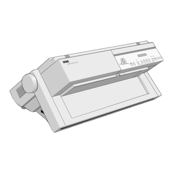
What Your New Printer Offers Thank you for choosing a DIGITAL Matrix Printer LA400plus. This chapter describes the main characteristics of your new printer. d400-c02 DIGITAL Matrix Printer LA400plus Paper Handling Flexibility The DIGITAL Matrix Printer LA400plus is able to feed paper through different paths, allowing you to quickly switch between different paper types or print tasks. -
Page 54: Connectivity
Printing on Several Types of Paper The DIGITAL Matrix Printer LA400plus is able to handle a variety of paper types, from standard paper up to the heaviest multipart paper, including labels and envelopes. -
Page 55: Ease Of Use
What Your New Printer Offers Ease of Use Your DIGITAL Matrix Printer LA400plus offers various features supported by a series of automatic operations, for maximum ease of use. The Tear/View mode allows the automatic and precise advance of the paper at the end of each print task, so that you can easily tear it off. -
Page 57: Getting To Know Your Printer
Getting to Know Your Printer This chapter describes the major parts and controls of your DIGITAL Matrix Printer LA400plus. To find out how to assemble, connect, and set up your printer, see the Setting Up Your Printer section at the beginning of this guide. - Page 58 Getting to Know Your Printer d400-c02 d400-c03 & " £ d4003b20...
-
Page 59: Parts Of The Printer
Getting to Know Your Printer Parts of the Printer The figures on the previous page show a front, rear and internal view of the printer. The following parts are indicated: Front and Left View Power switch Platen knob (to feed the paper manually) Top cover (to protect print head and the printer carriage) Operator panel (to control the printer) Cut sheet stand (for the Manual paper path) -
Page 60: The Ribbon Cartridge
The impact of the print head needles on the ribbon applies the ink to the paper. Your DIGITAL Matrix Printer LA400plus can use either a black ribbon or a color ribbon, if the color mechanism is installed (see section "Preparing for Color Printing" in Appendix A "Supplies and Options"). -
Page 61: The Push Tractor Unit
Getting to Know Your Printer The Push Tractor Unit The following figure shows you the Push tractor unit which is a paper feeding device used to load continuous form into the printer. According to your needs, the Push tractor unit can be mounted in Front position or in Rear position. -
Page 62: The Push Tractor Unit In Front Position
Getting to Know Your Printer The Push Tractor Unit in Front Position The mounting of the Push tractor unit in Front position is described at Step 6 "Loading Continuous Form" in the Setting Up Your Printer section you find at the beginning of this guide. The Push tractor unit installed in the Front position feeds the paper from the front slot ejects it through the rear slot d4001a15... -
Page 63: The Push Tractor Unit In Rear Position
Getting to Know Your Printer The Push Tractor Unit in Rear Position The installation procedure of the Push tractor unit in Rear position is described in Chapter 3 "Handling Different Types of Paper" of this User Guide. With the Push tractor unit in this position, the paper is fed through the rear entry slot and is ejected through the rear paper slot. -
Page 64: The Operator Panel
Getting to Know Your Printer The Operator Panel The operator panel is positioned on the front right side of the printer. It includes nine function buttons, a 16-character display, three state and five Paper Path indicators. Operator Panel The display shows the messages regarding the printing functions and the operating state of the printer. -
Page 65: The State Indicators
Getting to Know Your Printer The State Indicators The DIGITAL Matrix Printer LA400plus operator panel has three state indicators: Fault Ready Set-Up Indicator State Meaning Ready Ready lit. The printer is in Ready or Busy state. The printer can receive printing information from the host. -
Page 66: The Paper Path Indicators
Getting to Know Your Printer The Paper Path Indicators The Paper Path indicators identify which Paper Path is selected. A Paper Path is mainly defined – the paper feeding device used – the position of the paper feeding device on the printer Two paper feeding devices are available: –... -
Page 67: The Buttons
Getting to Know Your Printer Indicator Status Meaning Paper Path indicator lit. The Paper Path corresponding to the lit indicator is selected. In this example the Push-Front Paper Path is selected. Paper Path indicator blinking. The Paper Path corresponding to the blinking indicator is selected, but it is out of paper. -
Page 68: The Operating States
Getting to Know Your Printer The Operating States The following definitions explain the printer operating states. A state is a specific situation essentially characterized by the data flow interpretation and the physical configuration of the printer transmitted through the different sensors. The first part of the display indicates the current operating state (see the section "The Display"... - Page 69 Getting to Know Your Printer Operating Modes Definition Normal This is the basic operating mode of your printer, allowing you to perform all the operations related to getting documents printed: printing, handling paper, selecting fonts, managing the operating states, switching between your customized configurations.
-
Page 70: The Function Of The Buttons In Normal Mode
Getting to Know Your Printer The Function of the Buttons in Normal Mode As explained previously, the function of the button mainly depends on the operating mode but is also affected by the printer state. Normal mode gives you direct access to the following button functions: Button Functions... - Page 71 Getting to Know Your Printer Button Functions Purpose Ready/Pause State Busy State Fault State Paper Out Other Fault Font - To force one of the Inactive Same as for Inactive Font available resident fonts. Ready/Pause See "Selecting Print state. Features" in Chapter 4. - To select Macro 3.
-
Page 72: The Function Of The Buttons In Set-Up Mode
Getting to Know Your Printer The Function of the Buttons in Set-Up Mode As explained previously, the function of the button mainly depends on the operating mode. The printer state also affects the specific function purpose. By definition, you access the following button functions in Set-Up mode, that is after pressing the button. - Page 73 Getting to Know Your Printer Button Functions Purpose In the Set-Up structure, to navigate at the same level to the previous item. See "How to Configure Your Printer" in Chapter 6. Sel/Save To select a Value and save the new Configuration. See "How to Configure Your Printer"...
-
Page 74: The Functions Of The Buttons In Top Of Form Mode
Getting to Know Your Printer The Functions of the Buttons in Top of Form Mode As explained previously, the function of the button mainly depends on the operating mode but is also affected by the printer state. You access the following button functions in the Top of Form mode, that is after pressing the button. -
Page 75: The Display
Getting to Know Your Printer The Display The display reads different types of messages according to the printer state and the operating mode. The Basic Screen The basic screen is displayed in Normal mode. It is overwritten with interactive messages which are described in a section below. -
Page 76: The Font/Pitch Screen
Getting to Know Your Printer Macro Message Meaning The Macro 1 is selected. The Macro 2 is selected. The Macro 3 is selected. The Macro 4 is selected. Protocol Message Meaning The DEC PPL2 protocol is selected. The IBM Proprinter XL24E protocol is selected. The Alternate Graphic Mode of the IBM Proprinter XL24E protocol is selected. - Page 77 Getting to Know Your Printer When you first access the Font/Pitch screen, the display reads the following Factory setting for the font and the pitch: Font Messages Pitch Messages Common Meaning SoftContrl. Soft. Software Control Draft Software Control means that the font and the pitch that are used by the printer are defined through the commands of your software application.
-
Page 78: The Different Types Of Interactive Messages
Getting to Know Your Printer The Different Types of Interactive Messages The interactive messages can be divided into the groups which are introduced below. See Appendix C "LCD Display Messages" for a complete list of the display messages. The User Instruction Messages These interactive messages are displayed when you have to perform specific operations. -
Page 79: Handling Different Types Of Paper
Handling Different Types of Paper Paper Types Your printer is able to handle various types of paper: simple or multipart paper for cut sheet or continuous form. In addition, you can also print on envelopes and labels. The following specifications should be adhered to in order to assure reliable operation. Paper not conforming to these specifications may be used with the printer, however, the results are not guaranteed. -
Page 80: Multipart Paper
Handling Different Types of Paper Multipart Paper Multi-parts form demands special consideration because of itscomplexity. Adherence to tolerances and environmental conditions is more critical than with simple part. The width tolerances and storage conditions specified for simple part also apply to multipart paper. There are many different types of multipart paper available;... -
Page 81: Push-Front
Handling Different Types of Paper Push-Front Path-e The Push-Front Paper Path Continuous form loaded with the Push tractor unit installed in the front position. The paper is input into the printer through the front paper slot and is output through the rear paper slot. Push-Rear Path-a The Push-Rear Paper Path... -
Page 82: Manual
Handling Different Types of Paper Manual Path-b The Manual Paper Path Cut Sheets, envelopes or particular paper formats loaded through the cut sheet stand. Pull Path-c The Pull Paper Path Continuous form loaded from the front and fed with the Pull tractor unit (option). Push+Pull Path-d The Push+Pull Paper Path... -
Page 83: How To Select A Paper Path
Handling Different Types of Paper How to Select a Paper Path The selection of the paper path can be done using the printer driver with your application software. There are also two ways of selecting the paper path operating on the printer. –... -
Page 84: Using The Operator Panel
Handling Different Types of Paper Using the Operator Panel button on the operator panel is used to select the paper path you want to use. To select a Path paper path using the operator panel: 1. Press the Path button. The indicator corresponding to the currently selected path starts blinking. -
Page 85: Cut Sheets
Handling Different Types of Paper Paper Path Paper type Document Type Advantages Disadvantages Pull High thickness Program listings Straight paper Specific routing, needs routing the optional Pull tractor Great choice: Adhesive labels Not possible to use other Simple part paper paths Multiparts with chemical or carbon No reverse paper... -
Page 86: Envelopes
Handling Different Types of Paper Envelopes Paper Path Paper Type Document Type Advantages Disadvantages Manual Maximum Normal and Best paper routing Sheet by sheet feeding. thickness: 0,3 mm preprinted envelopes Allows printing on paper without any option mounted Adhesive Labels Paper Path Paper Type Document Type... -
Page 87: Handling Continuous Form
Handling Different Types of Paper Handling Continuous Form The DIGITAL Matrix Printer LA400plus allows a great number of continuous form handling features. In addition to the Push-Front and Push-Rear paper paths, the use of the optional Pull tractor unit gives you access to the Pull and the Push+Pull paper path. -
Page 88: Handling Continuous Forms Using The Push Tractorin Front Position
Handling Different Types of Paper Handling Continuous Forms using the Push Tractorin Front Position Mounting the Push Tractor Unit in Front Position Warning: Before mounting or removing any paper feeding device, power-off the printer. 1. Remove the Push tractor unit from its plastic packet. - Page 89 Handling Different Types of Paper 4. Identify the place of the Push tractor unit in the printer. The electrical connector must be on the right. d4001a54 Identifying the Tractor Unit Place 5. Mount the Push tractor unit in its place , inserting the electrical connector into the corresponding plug on the printer and aligning both its left and bottom sides with the printer casing.
- Page 90 Handling Different Types of Paper 6. Push both the left and right sides of the Push tractor unit upward, until it is fully engaged. d4001a07 Engaging the Tractor Unit Note: The Push tractor is engaged when you feel and hear the click of both left and right buttons .
-
Page 91: Loading The Paper
Handling Different Types of Paper Loading the Paper Your DIGITAL Matrix Printer LA400plus is factory set to have the left tractor already positioned for the first printable column. Some of the following steps may thus not be necessary. The following photos show the installation of 80-column paper. - Page 92 Handling Different Types of Paper 3. Close the door of the left tractor and, if necessary, adjust the position of both paper supports along the tractor bar to get equal intervals between them and the edges of the paper. d4001a11 Positioning the Paper Supports Along the Tractor Bar 4.
- Page 93 Handling Different Types of Paper 5. If necessary, move the right tractor along the tractor bar to position its pins in front of the pinfeed holes of the paper. Place the pinfeed holes on the same tractor pins as on the left tractor, so that the top edge of the paper is parallel to the tractor bar.
- Page 94 Handling Different Types of Paper 6. Close the door of the right tractor and check that the left edge of the paper is aligned with the right edge of the green mark on the printer casing. This position allows you to print the first column against the left side of the printable area (no left margin).
- Page 95 Handling Different Types of Paper 7. Once the paper is properly positioned, lock the left tractor on the tractor bar by pushing up its locking lever and, if necessary, adjust the right tractor position so that the paper is fairly taut and appears to lay flat on the paper supports.
- Page 96 Handling Different Types of Paper 10. Close the front cover by pushing down on both corners. The front cover is properly closed when it clicks into place and its edges are aligned with the printer casing. d4001c17 Closing the Front Cover 11.
-
Page 97: Removing The Push Tractor Unit From Front Position
Handling Different Types of Paper Removing the Push tractor Unit from Front Position Warning: Before mounting or removing any paper feeding device, power-off the printer 1. If paper is loaded in the Push-Front paper path, park the paper on the Push tractor pressing the Set-Up button followed by the Park... - Page 98 Handling Different Types of Paper 4. Close the gear protection rotating it upwards. d4002a04 Closing the Gear Protection 5. Close the front cover. 3-20...
-
Page 99: Handling Continuous Forms Using The Push Tractor In Rear Position
Handling Different Types of Paper Handling Continuous Forms using the Push Tractor in Rear Position Warning: Before mounting or removing any paper feeding device, power-off the printer. Mounting the Push Tractor in Rear Position 1. Remove the large rear cover d4001c20 Removing the Large Rear Cover 2. - Page 100 Handling Different Types of Paper 3. Reposition the large rear cover d4001c22 Repositioning the Large Rear Cover 4. Identify the correct insertion direction of the Push tractor : the electric connector must be on the left and the tractor grooves face down.
- Page 101 Handling Different Types of Paper 5. Push the Push tractor unit into the printer on both sides until it engages. d4001a51 Mounting the Tractor Unit Note: The Push tractor is engaged when you feel and hear the click of both left and right buttons .
-
Page 102: Loading The Paper
Handling Different Types of Paper Loading the Paper Your DIGITAL Matrix Printer LA400plus is factory set to have the left tractor already positioned for the first printing column. Some of the following steps may therefore not be necessary. The following photos show how to load 80-column paper. - Page 103 Handling Different Types of Paper 2. Open the door of the left tractor. Insert the paper under the paper separator . If necessary, adjust the position of both paper supports along the tractor bar to get equal intervals between them and the edges of the paper d4001c28 Positioning the Paper Supports 3.
- Page 104 Handling Different Types of Paper 4. Open the door of the right tractor, then to facilitate placing of paper on the tractor pins, unlock the tractor by pushing up its locking lever . If necessary, move the right tractor along the tractor bar to position the pins in front of the pinfeed holes of the paper.
- Page 105 Handling Different Types of Paper 6. Check that the left edge of the paper is aligned with the right edge of the green mark the printer casing. This position allows you to print the first column against the left side of the printable area (no left margin).
- Page 106 Handling Different Types of Paper 7. Lock the left tractor on the tractor bar by pushing down its locking lever. If necessary, adjust the right tractor position so that the paper is moderately taut and appears to lay flat on the paper supports.
- Page 107 Handling Different Types of Paper 10. Press the button. FF/Load The message "Loading paper..." appears on the display and the paper is loaded into the printer. When the paper stops, the Push-Rear indicator is on, the Fault indicator is off and the display shows "Ready M1-Aut.".
-
Page 108: Removing The Push Tractor Unit From Rear Position
Handling Different Types of Paper Removing the Push Tractor Unit from Rear Position Before mounting or removing any paper feeding device, power-off the printer. Warning: 1. Park the paper on the Push tractor unit by pressing the Set-Up button followed by the Park button. - Page 109 Handling Different Types of Paper 4. Mount the rear slot cover again by pushing it down into place. d4001a57 Installing the Rear Slot Cover 3-31...
-
Page 110: Parking The Paper
Handling Different Types of Paper Parking the Paper Paper parking is the function which moves the paper out of the printing sector (the area between the print head and the platen). When you decide to remove the paper from the printer, the paper must be parked first. -
Page 111: Printing On Cut Sheets
Handling Different Types of Paper Printing on Cut Sheets Your printer gives you the possibility to print also on cut sheets, which are loaded through the cut sheet stand on the front part of the printer, using the Manual paper path. Note: The Manual paper path is always available as soon as you insert a sheet. - Page 112 Handling Different Types of Paper 2. Position the left paper guide against the third large mark of the cut sheet stand and present a sheet without actually inserting it into the slot. Check that the left edge of the paper is aligned with the right edge of the third large mark This position allows you to print the first column against the left side of the printable area (no left margin).
- Page 113 Handling Different Types of Paper 3. Adjust the right paper guide according to the cut sheet width. Note: Be careful not to fold the sheet. d4001c27 Adjusting the Right Paper Guide 4. Insert the sheet in the slot until it stops against the paper feed rollers. Carefully follow the paper guides.
-
Page 114: Ejecting Cut Sheets
Handling Different Types of Paper 5. Hold the sheet against the rollers until they load the paper. The message "Loading paper..." appears on the display and the paper is fed to the first printable line, according to Set-Up settings. Note: It is not necessary to select the Manual paper path before inserting the sheet. -
Page 115: Printing On Adhesive Labels
Handling Different Types of Paper Printing on Adhesive Labels When printing on adhesive labels, use one of the straight paths, that is Push-Front, Pull or Push+Pull. Do not use the Push-Rear path. You must also disable the backward movement of the paper, because the unsticking of the labels can cause paper jams when the paper is moved backwards. -
Page 116: Moving The Paper
Handling Different Types of Paper Moving the Paper To move the paper we recommend you to only use the operator panel buttons: • Advances the paper one line at the current vertical pitch. • FF/Load: Advances the paper depending on the setting of the TEAR/VIEW MODE Option. See Chapter 6 "Configuring Your Printer". -
Page 117: Viewing The Last Printed Line
Handling Different Types of Paper Viewing the Last Printed Line The TEAR/VIEW MODE Option of the Set-Up allows you to manage the automation of paper movements related to specific purposes. Viewing the last printed line during a print task is affected by this automation management. -
Page 118: Advancing The Paper For Tearing-Off
Handling Different Types of Paper Advancing the Paper for Tearing-off The TEAR/VIEW MODE Option of Set-Up mode allows you to manage the automation of paper movements for specific purposes. Advancing the paper for tearing-off is affected by this automation management. The following description shows an example of how to use your printer features in the most automatic way possible. -
Page 119: Operating Your Printer
For the DIGITAL Matrix Printer LA400plus, such parameters are called Values. These Values are sorted within Functions, Options and Sub-options. The Macro is one of the Functions within the printer Configuration. -
Page 120: Switching Between Macros
Operating Your Printer Switching between Macros To switch between the Macros: 1. Press the button on the operator panel. Macro The display shows Select a Macro. Selecting a Macro 2. Within 3 seconds press the button corresponding to the Macro you want to use. -
Page 121: Selecting Print Features
Operating Your Printer Selecting Print Features There are three possibilities to select the print features you need for a specific print task: • By customizing a Macro. This allows you to alter the greatest number of print parameters. Within the Option list of the Macros, you can define: –... -
Page 122: Selecting The Font
Operating Your Printer Selecting the Font Font button allows you to select one of the following resident fonts: Draft - HiDraft - Courier - Roman - Sans Serif - Prestige - Script - Orator - OCR-A - OCR-B You can also select the SoftContrl (Software Control) Value. Software Control means that the font that is used by the printer is defined through the commands of your software application. -
Page 123: Selecting The Pitch
Operating Your Printer Selecting the Pitch button on the operator panel allows you to select different horizontal pitches according Pitch to the selected protocol. See Chapter 7 "Customizing a Macro" for the pitch values. You can also select the Soft. (Software Control) Value. Software Control means that the pitch that is used by the printer is defined through the commands of your software application. -
Page 124: Reducing The Print Noise Level
Operating Your Printer Reducing the Print Noise Level To print with a reduced noise level (Quiet mode). • Press the button. Quiet The display shows Quiet instead of the current printer state. To return to Normal mode: • Press the Quiet button again. -
Page 125: Printing
Printing Print Area Definition For the correct definition of the print area, customize the printer Set-Up Macros according to your needs. The corresponding Options are the following: • FORM LENGTH • LEFT MARGIN • FORM WIDTH • TOP MARGIN • BOTTOM MARGIN •... - Page 126 Printing Print Area Definition • ToF (Top of Form) : This value defines the distance between the edge of the paper and the place where you allow the printing to begin (position of Line #1). You can adjust this distance according to the condition of your paper (for example pre-printed forms).
- Page 127 Printing 1 2 3 4 5 6 ABCDEFGHIJ... ABCDEFGHIJ... ABCDEFGHIJ... ABCDEFGHIJ... ABCDEFGHIJ... Print Area Definition...
-
Page 128: Printing On Multipart Form
Printing Printing on Multipart Form Once you have decided which paper format you are using, you can start sending the print tasks. The printer loads the paper in the current paper path as soon as it receives data. If you are using application software which uses the printer driver to manage the print jobs, make sure that the Paper Format and the Print Area match the paper installed on the printer. -
Page 129: Hints On Printer Settings For Paper Thickness
For more details about the paper thickness setting, see the section "Setting the Printing Modes" in Chapter 7 "Customizing Macros". Managing Blank Pages Thanks to the Tear/View mode feature for advancing paper for tear off, your DIGITAL Matrix Printer LA400plus allows you to save paper by removing unnecessary blank pages between print jobs. -
Page 130: Printing On Pre-Printed Forms
Printing Printing on Pre-printed Forms When printing on Pre-printed forms, you may need to reposition the paper in order to align the printout with the predefined areas on the paper. This operation is performed by adjusting the Top of Form Value (see the Top of Form definition in the section" Print Area Definition", above). You can access the Top of Form setting, either in the Macro Option List in Set-Up mode or simply from the operator panel. -
Page 131: Quickly Switching Between Two Paper Types
Printing Quickly Switching between Two Paper Types The basic configuration of your DIGITAL Matrix Printer LA400plus allows you to quickly switch between the Push-Front (or the Push-Rear) and the Manual paper paths, by simply pressing the button at the operator panel. See Chapter 3 "Handling Different Types of Paper"... -
Page 132: Configuring Your Printer
Configuring Your Printer What is Configuration? Configuration is the whole set of parameters that define the printer usage characteristics such as communication interface, protocol, fonts, paper path etc. Configuring your printer is necessary to make it operate and communicate properly with your hardware and software. You access the Configuration using Set-Up mode. -
Page 133: The Configuration Structure
Configuring Your Printer The Configuration Structure The Set-Up Configuration contains seven Functions, which group specific Options. The Options, if necessary, are broken down into other Sub-options. The selectable parameters defining the Options or Sub-options are called Values. The following is an example of part of the Configuration structure. -
Page 134: Display Graphic Conventions
Configuring Your Printer Display Graphic Conventions To allow you to recognize the kind of item that appears on the printer display, the following graphic conventions apply: Display Sample Convention Meaning MACRO Uppercase This convention applies to Functions, Options and Sub-options (all non-selectable items). -
Page 135: Configuration Quick Reference
Configuring Your Printer Configuration Quick Reference See the following pages to know the Functions, Options, Sub-options and Values defining the entire Configuration. Macros Installation Interface Test/Hex-Dump User Access User Adjustments Save Configuration Functions Note: In the Value list, the Factory setting is shown in bold. - Page 136 Configuring Your Printer Macros Installation Interface Macro 1 Language Interface Type Macro 2 Error Buzzer I/F Time-out Input Buffer Macro 3 Path at Power-on Parallel Mode Macro 4 AUTOFEED Signal See pages 6-6, 6-7 See page 6-7 SLCT-IN Signal Discon. on Fault Test/Hex-Dump User Access Word Length...
- Page 137 Configuring Your Printer Macro 1/2/3/4 Protocol Form Length Print Direction Protocol Serial 3 inches Unidirectional DEC PPL2 3.5 inches Bidirectional EPSON ESC/P2 4 inches Soft. Control IBM XL24E 5.5 inches Line Mode Protocol Paral. 6 inches LF=LF,CR=CR DEC PPL2 7 inches EPSON ESC/P2 (M1/M3) LF=LF+CR 8 inches...
- Page 138 Configuring Your Printer Macro 1/2/3/4 Installation Tear/View Mode IBM Mode Language Auto.advance 1s Horizontal Pitch English Auto.advance 2s IBM C-Set Deutsch Auto.advance 3s Code Page Español Auto.advance 4s IBM Dbl. Height Français Auto.advance 5s IBM AGM Italiano Manual advance Pitch/COMPRESS Error Buzzer No tear/reverse Slashed Zero...
- Page 139 Configuring Your Printer DEC Mode Horizontal Pitch G0 Character Set Wrap vs Truncate 5 cpi US ASCII Wrap 6 cpi British Truncate 6.6 cpi DEC Finnish Printer ID 8.25 cpi French PPL2 8.55 cpi DEC French-Can. LA120 ID 9 cpi German LA210 ID 10 cpi...
- Page 140 Configuring Your Printer IBM Mode Horizontal Pitch Code Page IBM Dbl. Height Code Page 210 10 cpi Disabled Code Page 220 12 cpi Enabled Code Page 437 17.1 cpi IBM AGM CP 437 Greek 20 cpi Disabled Code Page 850 Prop.
- Page 141 Configuring Your Printer EPSON Mode Horizontal Pitch Code Page EPSON C-Set Code Page 210 10 cpi Graphic 12 cpi Code Page 220 Italic Code Page 437 17.1 cpi Slashed Zero CP 437 Greek 20 cpi Code Page 850 Prop. Spacing Code Page 852 National C-Set Code Page 853...
- Page 142 Configuring Your Printer Interface Interface Type SLCT-IN Signal Parity Bit Automatic Disabled None Parallel Enabled Even Serial Discon. on Fault I/F Time-out Buffer Control No discon. 2 seconds Yes (DTR drop) XON/XOFF (2 to 30 seconds) XON/XOFF + DTR Yes (DTR pulse) Input Buffer Word Length Robust XON...
-
Page 143: How To Configure Your Printer
Configuring Your Printer How to Configure your Printer Reaching, Selecting, Saving a Configuration Value When you press the Set-Up button, the printer enters Set-Up mode allowing you to navigate within the Configuration structure. Use the Arrows buttons to move around in the structure. Reaching a Configuration Item Button Purpose... -
Page 144: Example Configuring
Configuring Your Printer Example Configuring The following is an example Configuration procedure, in which we will alter the Factory settings: the font is changed from Draft to Orator and the horizontal pitch is changed from 10 cpi to 17.1 cpi in DEC protocol for Macro 2. 1. -
Page 145: Printing The Printer Configuration
Configuring Your Printer 15. Press the button. The display shows Save config.. Exit 17. To permanently save your changes, press the Sel/Save button. The display shows Processing..., indicating that the parameters are copied in the printer memory. Printing the Printer Configuration To check the values set in the printer Configuration, proceed as follows: 1. - Page 146 Configuring Your Printer The Configuration Sheet Code version Macro Option List Current Values of the current Macro Macros (the asterisk in the title bar identifies the current Macro) Power-on Values of the INSTALLATION Function Power-on Values of the USER ADJUSTMENTS Function Power-on Value of the USER ACCESS Function Power-on Values of the INTERFACE Function 6-15...
-
Page 147: How To Manage Your Configuration
Configuring Your Printer How to Manage your Configuration The SAVE Function allows you to manage your printer Configuration. Function Executable Values SAVE Save Config. Restore Macro X Rest.all Macros Recall Factory You scroll the Values pressing the button. Saving a Configuration When you have finished selecting the Values, press the button. -
Page 148: Setting The Printer Installation
Configuring Your Printer Setting the Printer Installation The installation Values are generally set once when the printer is integrated within its operating environment. The settings concern the printer hardware Configuration and the communication parameters. Use the INSTALLATION Function to alter these parameters. Note: Factory settings are shown in bold. -
Page 149: Paper Path At Power-On
Configuring Your Printer Paper Path at Power-On The PATH AT POWER-ON Option allows you to decide which path you want to be selected, when the printer is powered-on. Value Definition Last sel. Path The paper path at power-on is the one that was selected before the printer was powered off. -
Page 150: Input Buffer Size
Configuring Your Printer Input Buffer Size The INPUT BUFFER Option allows you to set the input buffer size. Value Definition 1 K (DLL) 1 KByte input buffer. 8 K (No DLL) 8 KByte input buffer. No Down-Line-Loading possible. 16 K (No DLL) 16 KByte input buffer. -
Page 151: Select-In Signal
Configuring Your Printer SELECT-IN Signal The SLCT-IN SIGNAL Option allows you to determine if the parallel interface ignores the SELECT-IN signal or not. Value Definition Disabled The parallel interface ignores the SELECT-IN signal. Enabled The parallel interface uses the SELECT-IN signal. Setting the Serial Interface Disconnection on Fault The DISCON. -
Page 152: Parity Bit
Configuring Your Printer Value Option 9600 bps 9600 bits per seconds. 19200 bps 19200 bits per seconds. 38400 bps 38400 bits per seconds. Parity Bit The PARITY BIT Option allows you to set the parity check type. Value Definition Even The even parity check is used. -
Page 153: Setting The User Access Authorization
Configuring Your Printer Setting the User Access Authorization The access to the printer Configuration can be protected in different ways. The different values of the USER ACCESS Function affect both access to Set-Up mode and use of the operator panel. The following table shows the setting effects. User Access Value Set-Up Mode Operator Panel... -
Page 154: Customizing Macros
Customizing Macros How to Customize a Macro Your DIGITAL Matrix Printer LA400plus allows you to use four sets of pre-determined parameters called Macros. You can alter the factory settings of the Macro Options and customize them as explained in this chapter. -
Page 155: Setting The Publishing Style
For each of the interfaces, you can then select one of the following protocols: Value Definition DEC PPL2 Sets the DEC PPL2 protocol to communicate with Digital or ANSI-compatible host software. This is the Factory setting when using the serial protocol. IBM XL24E Sets the IBM Proprinter XL24E protocol to communicate with host software. -
Page 156: Vertical Pitch
Customizing Macros Vertical Pitch The vertical pitch determines the density with which the lines are printed. The VERTICAL PITCH Option allows you to select this density according to different units: – Lines printed per inch (lpi): 2, 3, 4, 6, 8, 10 or 12 lpi –... -
Page 157: Left Margin
Customizing Macros – The NUMBER OF LINES Sub-option gives you the possibility to define the logical form length as a number of lines. This length comes then from the following formula: Form length (inches) = Vertical pitch (lpi) x Number of lines (unit conversion is automatic if you define the vertical pitch unit as lpcm) Note: - The maximum authorized form length is 21 inches. -
Page 158: Top Of Form
Customizing Macros Top of Form The TOP OF FORM Option is used to set the Top of Form position. See the print area definition, in Chapter 5 "Printing". This Option is useful when printing on preprinted forms, where a precise positioning is required. -
Page 159: Setting The Printing Modes
Customizing Macros Setting the Printing Modes Print Direction The PRINT DIRECTION Option allows you to define the print direction when a line feed occurs. Value Definition Unidirectional The printing direction is the same each time. This setting may be necessary due to specific drivers compatibility. Bidirectional The print direction changes for each line feed. -
Page 160: Blank Pages
Customizing Macros Blank Pages The BLANK PAGES Option offers you another way to save paper. This Option tells the printer how to behave when receiving a form feed command that would cause a blank page: Value Definition Removed The printer does not perform form feeds that result in blank pages. Preserved The printer may perform form feeds that result in blank pages. -
Page 161: Print Gap
Customizing Macros Print Gap The distance between the print head and the platen can be adjusted with the PRINT GAP Option as follows: Value Definition Auto. adjust. Automatic gap adjustment is performed. The print head adjusts the platen gap automatically according to the paper thickness each time you load paper into the printer or change the paper path. - Page 162 Customizing Macros To adjust the print gap manually: 1. Select the Manual adjust. Value for the PRINT GAP Option. 2. Save your changes and exit the Set-Up mode. The display shows Print gap: Manual/Adjust print gap. 3. Open the top cover. The print head automatically moves to the center, letting you access to the print gap selection knob behind and at the left of the left cartridge support.
-
Page 163: Automatic Gap Offset
Customizing Macros Automatic Gap Offset When selecting the Auto adjust. Value for the PRINT GAP Option, adjust the Value of the AUTO.GAP OFFSET Option according to your print out quality. Try different settings to get the expected print result. The AUTO.GAP OFFSET Value is Factory set to 0. The Values range between -8 and +8. Perforation Anti-jam The PERFO. -
Page 164: Setting The Tear/View Mode
Customizing Macros Setting the Tear/View Mode The main purposes of the TEAR/VIEW MODE Option are the following: – to allow you to automatically move the paper perforation to the tear bar (Tear-off position, ) when a print task is completed. –... -
Page 165: Automatic Advance Setting
Customizing Macros Automatic Advance Setting Print Job Completed Currently Printing Without final <FF> With final <FF> Position - State Position - State Position - State 4 - Ready after timeout 5 - Ready after timeout Busy 1. Pause 4 - Pause 5 - Pause 4 - Pause 2. -
Page 166: Paper Position Definition
Customizing Macros Paper Position Definition Position Definition Print head on last printed character while printing or at next line at the end of a job. Print head on first next Top of Form. Print head on second next top of form. 7-13... - Page 167 Customizing Macros Position Definition Viewing position Last printed line facing the tear bar. Tear-off position Next perforation facing the tear bar. Second perforation facing the tear bar. 7-14...
-
Page 168: Setting The Dec Mode
Customizing Macros Setting the DEC Mode The DEC MODE Option sets the DEC protocol specific features. This Option comprises the following Sub-options: Sub-options Definition HORIZONTAL PITCH Sets the horizontal spacing of the printed characters G0 CHARACTER SET Selects the used G0 Character Set. USER PREF. -
Page 169: G0 Character Set
Customizing Macros G0 Character Set The G0 CHARACTER SET Sub-option sets the G0 character set that will be used with the DEC protocol. The following resident character sets are available: Value Definition US ASCII US ASCII British British French French German German Norw./Danish... -
Page 170: User Preference Character Set
Customizing Macros User Preference Character Set The USER PREF. C-SET Option sets the user character set for the DEC protocol. The following character sets are available: Value Definition DEC Supplement DEC Supplemental DEC Spec.Graph. DEC Special Graphics DEC Technical DEC Technical DEC 7bitHebrew DEC 7Bit Hebrew DEC 7bit Turkish... -
Page 171: Wrap Or Truncate
Customizing Macros Wrap or Truncate The WRAP vs TRUNCATE Option determines the printer behaviour when receiving text that exceeds the right margin. Value Definition Wrap Text beyond the right margin moves to the left margin of the next line. See the following figure. Truncate The printer ignores any character beyond the right margin. -
Page 172: Initial Report
Customizing Macros Initial Report The INIT. REPORT Option determines whether the printer sends an initial report to the host or not. Value Definition Enabled The Initial Report is sent to the host. Disabled No Initial Report is sent to the host. Automatic ANSWERBACK The AUTO. -
Page 173: Configuring The Ibm Mode
Customizing Macros Configuring the IBM Mode The IBM MODE Option sets the IBM protocol specific features and comprises the following Sub-options: Sub-options Definition HORIZONTAL PITCH Sets the horizontal spacing of the printed characters. IBM C-SET (1/2) Selects whether the IBM Character Set 1 or 2 is used. CODE PAGE Selects the Code Page character sets. -
Page 174: Code Page
Customizing Macros Code Page The CODE PAGE Sub-option identifies which Code Page is to use. Value Definition Code Page 210 Greek Code Page 220 Spain CP 437 GREEK Greek Code Page 437 Code Page 850 Multilingual Code Page 852 Eastern Europe Code Page 853 Turkish Code Page 855... -
Page 175: Ibm Double Height
Customizing Macros IBM Double Height The IBM DBL. HEIGHT Sub-option determines whether the IBM Double Height mode should be used (Enabled) or not (Disabled). IBM AGM The IBM AGM Sub-option determines whether the Alternate Graphics Mode should be used (Enabled) or not (Disabled). Horizontal Pitch on COMPRESS The PITCH/COMPRESS Sub-option selects the character density when receiving the COMPRESS command. -
Page 176: Horizontal Pitch
Customizing Macros Horizontal Pitch The HORIZONTAL PITCH Option sets the horizontal pitch used with the EPSON protocol. The values are 10, 12, 17.1, 20 cpi and Proportional Spacing (Prop. Spacing). National Character-Set The NATIONAL C-SET Sub-option identifies which national character set is to use. Value Definition France... -
Page 177: Code Page
Customizing Macros Code Page The CODE PAGE Sub-option identifies which Code Page is to use. Value Definition Code Page 210 Greek Code Page 220 Spain CP 437 Greek Greek Code Page 437 Code Page 850 Multilingual Code Page 852 Eastern Europe Code Page 853 Turkish Code Page 855... -
Page 178: Epson Character Set
Customizing Macros EPSON Character Set The EPSON C-SET Sub-option defines the style which is applied to the character set: Value Definition Graphic The character sets are not altered. Italic The Italic style is applied to the character set. Slashed Zero The SLASHED ZERO Sub-option selects whether the zero character is printed with or without a slash. -
Page 180: Testing Your Printer
Testing Your Printer The correct functioning of your printer can be checked using the TEST/HEX-DUMP Function of Set-Up mode. Note: To perform these tests paper must be already loaded in the printer. See Chapter 3 "Handling Continuous Forms". You access to the TEST/HEX-DUMP Function as follows: 1. -
Page 181: Printing The Self-Test
Testing Your Printer Printing the Self-Test The Self-Test printout consists of a header and an ASCII swirl pattern sequence for each resident font (at 10, 12 and 15 cpi for each font). Caution: The Self-Test checks also the correct print head movement along the whole carriage bar. -
Page 182: Hex Dump Printing
Testing Your Printer Hex Dump Printing The Hex Dump mode lets you print the received data as hexadecimal codes. To enable Hex-Dump mode: 1. Select the HEX-DUMP Mode Option of the TEST/HEX-DUMP Function. 2. Select the Enable Hex-D. Value. The printer switches directly to the Hex-Dump mode. The basic screen shows Hex instead of the current protocol. -
Page 184: Adjusting Your Printer
Adjusting Your Printer This printer gives you the possibility to finely adjust bidirectional printing, the position of the first printable line for printing and the perforation position for tearing-off. Note: Ensure that paper is loaded, before starting the tests. How to Adjust your Printer Use the USER ADJUSTMENTS Function to perform the adjustments mentioned above. -
Page 185: Adjusting The Bidirectional Alignment
Adjusting Your Printer Adjusting the Bidirectional Alignment To perform bidirectional alignment: 1. Display the current value of the BIDI. ALIGNMENT Option by pressing the button. 2. Press the Sel/Save button. The Bidirectional Alignment table is printed. Bidirectional Adjustment Table The current bidirectional offset Value is printed under the header. -
Page 186: Adjusting The Position Of The First Printable Line
Adjusting Your Printer Adjusting the Position of the First Printable Line The positioning of the continuous form fed with the tractor unit in Front Position or with the tractor unit in Rear position in Push mode can be finely adjusted with the LINE #1-FRONT or the LINE # 1-REAR respectively. -
Page 187: Adjusting The Tear-Off Position
Adjusting Your Printer Adjusting the Tear-off Position You can perform a fine adjustment of the Tear-off position to facilitate paper tearing. 1. Enter the USER ADJUSTMENTS Function as described before and select the TEAR-PERFO ALIGN. Option. 2. Press the button. The paper is parked, then loaded to the current tear-off position. -
Page 188: Maintenance
Maintenance Cleaning The Printer Caution: Make sure the printer has been turned off for at least 15 minutes before starting any cleaning operations because the print head may be hot. Periodic cleaning will help keep your printer in top condition so that it will always provide optimal performance. -
Page 189: Replacing The Ribbon Cartridge
Maintenance Replacing The Ribbon Cartridge Caution: Make sure the printer has been turned off for at least 15 minutes before replacing the ribbon cartridge, because the print head may be hot. When Replacing the Ribbon Cartridge When the print quality starts to become poor, the ribbon cartridge must be changed. The ribbon cartridge life is 15 million characters for the black ribbon and 2 million characters for each band of the color ribbon. -
Page 190: Transporting The Printer
Maintenance Transporting the Printer When you need to transport your printer, pack it into its original packaging to avoid damage. Follow the unpacking instructions in Step 1 of the Setting Up Your Printer section in reverse order. Packing the Printer Note: Do not forget to install the shipment locks. -
Page 192: Troubleshooting
This section describes the problems which may occur when using the printer and suggests possible solutions. You may not need the following since the DIGITAL Matrix Printer LA400plus provides on-line help on its display. In most cases, the display shows rolling messages when an error occurs. The first part of the message identifies the error, the second part suggests a solution. -
Page 193: Printing Problems And Solutions
Paper type is not correct. Use paper conforming to the paper specifications. See "Paper Specifications" in Appendix B. Ribbon cartridge type is not Use a Digital ribbon cartridge. See correct. "Supplies and Options Order Numbers" in Appendix A. Ribbon is not properly installed. - Page 194 Troubleshooting Symptoms Possible Cause Action/Resolution Dark or smudged printing Print head is too close to the paper. Check the PRINT GAP Option setting in Set-Up. See "Setting the Printing Modes" in Chapter 7. If the PRINT GAP Option is set to Auto.
- Page 195 Troubleshooting Symptoms Possible Cause Action/Resolution Overprint on the same lines. Line mode setting is not correct. Select the CR=LF+CR value for the LINE MODE Option in the Set-Up. See "Setting the Printing Modes" in Chapter 7. Next printed line starts where the Line mode setting is not correct.
-
Page 196: Paper Handling Problems And Solutions
Troubleshooting Paper Handling Problems and Solutions Symptoms Possible Cause Action/Resolution Paper path is obstructed. 1. Clear the Paper Path. Paper jam 2. Press to resume printing. Pause Possible messages: Push-Front jam Pinfeed holes of continuous form 1. Clear paper jam. Check paper are not placed properly on the 2. - Page 197 Troubleshooting If the message Remove paper appears on the display and no document is actually loaded in any of the paper paths: 1. Check that no paper debris or dust is present in front of the paper detection sensors. 2. If necessary clean them with air blow. The figure shows how to clean the front path sensor the rear path sensor and the manual path sensor Paper Detection Sensors...
-
Page 198: Printer Failure
Troubleshooting Printer Failure Symptoms Possible Cause Action/Resolution Electronic or mechanical internal Call Service. Printer failure. failure. Message: Printer failure Call Service. Hex-Dump Mode If the printer prints wrong characters, you can select the Hex-Dump Mode in the printer Test/Hex-Dump menu in order to analyze both printing and non-printing characters arriving on the printer. -
Page 200: Supplies And Options
Supplies and Options The following supplies and options are available for your DIGITAL Matrix Printer LA400plus. Note: See the corresponding part numbers at the end of this chapter. Supplies Supplies Description Black ribbon cartridge 15 million characters life Color ribbon cartridge... -
Page 201: Hints On Selecting The Proper Paper Path
Supplies and Options Hints on Selecting the Proper Paper Path Paper Path Paper type Document Type Advantages Disadvantages Pull High thickness Program listings Straight paper Specific routing, needs routing the optional Pull tractor Great choice: Adhesive labels Not possible to use other Simple part paper paths Multiparts with... -
Page 202: Mounting The Pull Tractor Unit
Supplies and Options Mounting the Pull Tractor Unit 1. Power the printer off. 2. Remove the large rear cover d4001c20 Removing the Large Rear Cover 3. Remove the rear slot cover d400c21 Removing the Rear Slot Cover... - Page 203 Supplies and Options 4. Reposition the large rear cover d4001c22 Repositioning the Large Rear Cover 5. Open the top cover and unhook the Pull tractor mechanism covers on the left and the right side. d4001b25 Unhooking the Pull Tractor Pins Covers...
- Page 204 Supplies and Options 6. Close the top cover and remove the Pull tractor mechanism covers on the left and the right side. d400a40 d400a39 Removing the Right Pull Tractor Mechanism Cover Removing the Left Pull Tractor Mechanism Cover 7. Remove the Pull tractor unit and the two cut-out Pull tractor pins covers from the plastic packet.
- Page 205 Supplies and Options 8. Hook the left cut-out Pull tractor pins cover with the cut-out towards the center of the printer on the two lateral plastic pins and gently push it down until it clicks in place.Repeat the same operation for the right cut-out Pull tractor pins cover d400a42 d400a41 Inserting the Right Cut-out Pull Tractor Pins Cover...
- Page 206 Supplies and Options 10. Present the Pull tractor unit with the electric connector on the left and mount it on the printer pressing it down until it clicks. Note: Let the Push tractor unit in front position to facilitate paper loading. d4002a51 Installing the Pull Tractor Unit...
-
Page 207: Loading Continuous Forms On The Pull Tractor Unit
Supplies and Options Loading Continuous Forms on the Pull Tractor Unit Note: Before loading thick paper into the printer, make sure that the print gap is set correctly. See Chapter 7 "Customizing Macros". To load continuous form onto the Pull tractor unit: 1. - Page 208 Supplies and Options 5. Open the left and right tractor doors d4001a60 d4001a58 Opening the Right Tractor Opening the Left Tractor 6. Check that the paper is taut and perfectly aligned with the paper path direction. Align the pinfeed of the Pull tractor unit with the paper pinfeed holes by moving the tractor bar with your fingers.
- Page 209 Supplies and Options 7. Move the left tractor along the tractor bar , in order to place the pinfeed holes of the paper on the tractor, and close the door d4001a52 Placing the Paper on the Left Tractor 8. Move the right tractor, place the paper on it and close the door d4004c29 Placing the Paper on the Right Tractor A-10...
- Page 210 Supplies and Options 9. Check that the paper is fairly taut and lock the left and right tractors in place by pulling the tractor locking buttons towards the front of the printer. d4005c29 Locking the Tractors in Place 10. – If you press , the current path will be the last selected path (Pull or Push+Pull).
-
Page 211: Set-Up Card
You prepare the Configuration on one printer, store it on the Set-Up card, copy the contents to other printers. In this way, in case you have a series of DIGITAL Matrix Printer LA400plus connected to your host, you need to configure only one printer. -
Page 212: Copying Your Configuration To The Set-Up Card
Supplies and Options 7. Press the button. Sel/Save The display shows Initializing..Once the initialization is complete, the display shows again the SetUp Card init. message. 8. Press the button. Exit Copying your Configuration to the Set-Up Card 1. Make sure the printer is powered off. 2. -
Page 213: Copying Your Configuration From The Set-Up Card
Supplies and Options Copying your Configuration from the Set-Up Card 1. Make sure the printer is powered off. 2. Insert the Set-Up Card into the slot and power the printer on. The display shows the blinking message SET-UP CARD MODE for 5 seconds. Then the display shows Printer <<... -
Page 214: Preparing For Color Printing
Supplies and Options Preparing for Color Printing To print in color you need the color mechanism option and a color ribbon cartridge. With the color ink ribbon cartridge installed, you can print up to seven colors. Preparing the Color Ribbon Cartridge The color ribbon cartridge is slightly different from the black ribbon cartridge. -
Page 215: Mounting The Color Mechanism
Supplies and Options Mounting the Color Mechanism Note: You need to use a Phillips screwdriver specified as follows: Ø = 4 mm, length = 10 cm. Caution: Before beginning with this operation, make sure that the print head is not hot. 1. - Page 216 Supplies and Options 4. Power the printer off and remove the ribbon cartridge, if any. 5. Insert the color mechanism connector into the connector of the print head . Plug it pushing it with the help of the screwdriver. d400b26 d400b27 Plugging the Color Mechanism Connector Inserting the Color Mechanism Connector...
- Page 217 Supplies and Options 7. Fix the color mechanism using the two screws d400b34 Fixing the Color Mechanism on the Carriage Assembly 8. Close the top cover. A-18...
-
Page 218: Installing The Color Ribbon Cartridge
Supplies and Options Installing the Color Ribbon Cartridge 1. Power the printer on. 2. Open the top cover The print head moves automatically to the center of the printer. d4001b20 Opening the Top Cover 3. Locate the front locking grooves of the left and right cartridge supports d4004b20 Front Locking Grooves... - Page 219 Supplies and Options 4. Push the mounting pins down onto the locking grooves 5. Align the center of the ribbon guide with the print head nose d4003b29 Positioning Cartridge/Aligning Ribbon Guide with Print Head Note: Turn the ribbon feed knob so that the left mounting pin is in contact with the locking grooves.
- Page 220 Supplies and Options 7. Push the cartridge down with your finger over the mounting pins. d4001b30 Locking the Ribbon Cartridge 8. Turn the ribbon feed knob to take up the ribbon slack. 9. Insert the plastic bracket on the black guide of the color mechanism Inserting the Plastic Bracket A-21...
- Page 221 Supplies and Options 10. Push the plastic bracket it down until it clicks. d4001b36 Pushing Down the Plastic Bracket 11. Close the top cover. A-22...
-
Page 222: Removing The Color Cartridge
Supplies and Options Removing the Color Cartridge 1. Power the printer on. 2. Open the top cover. The print head moves to the center of the printer. 3. Unlock the plastic bracket by pushing on the click d4002b32 Unlocking the Plastic Bracket 4. -
Page 223: Supplies And Options Order Numbers
Supplies and Options 5. Remove the ribbon guide from the print head. 6. Remove the cartridge from the locking pins and out of the printer. Supplies and Options Order Numbers Supplies Supply Order Number Black Ribbon Cartridge (15 Million characters life) LA40R-KA Color Ribbon Cartridge (2 Million characters life per band) LA40R-KC... -
Page 224: Technical Characteristics
Technical Characteristics Technical Specifications Printing Technique Impact dot matrix Print Head 24 printing elements with density of 180 dpi Print Speed (cps) Draft Letter Quality 10 cpi 12 cpi 15 cpi Throughput (pph) Letter Draft: 430 Letter Quality: 205 Graphic (90/180): 75 ECMA 132 - 10 cpi Spread 17: 225 Spread 10: 275... - Page 225 Technical Characteristics Print Styles Draft - High Impact Draft - Courier - Roman - Sans Serif - Prestige - Script - Orator - OCR-A - OCR-B - Data Block Printing Attributes Underline - double underline - overline - strike-through printing - bold - multicopy- double width - slant - color Character Sets DEC Protocol...
- Page 226 Technical Characteristics Physical Dimensions Height 12.4 inches (315 mm) Width 26.38 inches (670 mm) Depth 15.85 inches (390 mm) Weight 18 kg Standards, Regulations Printer Safety: UL Standard 1950 and Approvals IEC Publication 950 European Norm 60950 CSA Standard C22.2 No 950 AC Power 110 V +10/-15V 220 V +10/-15V...
-
Page 227: Paper Specifications
Technical Characteristics Paper Specifications Print Area This section illustrates the recommended print area for single sheets and continuous forms. 11.43 - 44.45 cm (4.5 - 17.5 inches) 4.23 mm (1/6 inch) 10.16 - 60,96 cm (4 - 24 inches) Print area 8 mm (0.32 inch) 3.81 mm 3.81 mm... - Page 228 Technical Characteristics 7,62 - 43,18 cm (3 - 17 inches) 4.23 mm (1/6 inch) 7,62 - 60,96 cm (3 - 24 Print area 4.23 mm (1/6 inch) Print area 8 mm (0.31 inch) Paper end 15 mm 15 mm (0.06 inch) (0.06 inch) Print Area for Continuous Form...
-
Page 229: Paper Thickness
Technical Characteristics Paper Thickness Paper thickness is given by the weight of the paper in either grams per square meter (g/m ) or in pounds per bond (lbs/bond). The following table shows the allowable paper thickness for one-part paper or for each sheet of multipart paper. The weight of carbonless or carbon-backed paper may vary, depending on the paper manufacturer. -
Page 230: Lcd Display Messages
LCD Display Messages Simple messages User Instructions Message Meaning Adjust print gap Requires manual setting of the print gap, when exiting Set-Up after having set the PRINT GAP Option to Manual adjust. See Chapter 7 "Customizing Macros" for more details. Load Manual Displayed when paper out occurs on the corresponding path or Load Pull... -
Page 231: Status Messages
LCD Display Messages Status Messages Message Meaning Manual The Manual path is selected via the operator panel. Pull The Pull path is selected via the operator panel. Push-Front The Push-Front path is selected via the operator panel. Push-Rear The Push-Rear path is selected via the operator panel. Push+Pull The Push-Pull path is selected via the operator panel. -
Page 232: Rolling Messages
LCD Display Messages Rolling messages Message Meaning 1.Check paper These messages are displayed during the initialization of the printer, 2.Press Pause when the Pull or Push+Pull paper path is selected. The user should check that the paper has been correctly loaded and confirm by pressing button. -
Page 234: Dec Ppl2 Quick Reference
DEC PPL2 Quick Reference This section contains basic information on the DEC PPL2 commands supported in the DIGITAL Matrix Printer LA400plus. The commands are listed by function, in the following order: – Positioning Controls and Tabs – Sheet size and margins –... - Page 235 Selective parameter, or one which identifies a list of options pertaining to the specific command. If ">" (3/14) or "?" (3/15) occurs at the beginning of a string of parameters, the following parameters are Digital private parameters. ">" or "?", if present must occur only once at the beginning of the parameter string.
- Page 236 DEC PPL2 Quick Reference Positioning Controls and Tabs Mnemonic Function Command Remarks C0 Control Code Backspace C0 Control Code Carriage Return 0/13 C0 Control Code Form Feed 0/12 C0 Control Code Horizontal Tab C0 Control Code Line Feed 0/10 C0 Control Code Vertical Tab 0/11 Horizontal Tab Set...
-
Page 237: Sheet Size And Margins
DEC PPL2 Quick Reference Sheet Size and Margins Mnemonic Function Command Remarks CSI Pn t DECSLPP Set Lines per Pn = number of lines per pages Physical Page CSI Pn1; Pn2 - u DECVPLA Set Vertical Page Pn1 = Position of the origin from top of form Length Alignment (in 1/72 in.) Pn2 = Paper length in 1/720 in. -
Page 238: Font Management And Attribute Selection
DEC PPL2 Quick Reference Type Size and Spacing, Managing Implicit Cursor Motion (cont.) Mnemonic Function Command Remarks CSI Ps z DECVERP Set Vertical Pitch Ps = 0: 6 LPI Ps = 1: 6 LPI Ps = 2: 8 LPI Ps = 3: 12 LPI Ps = 4: 2 LPI Ps = 5: 3 LPI Ps = 6: 4 LPI... - Page 239 DEC PPL2 Quick Reference Font Management and Attribute Selection (cont.) Mnemonic Function Command Remarks CSI Ps m Ps = 0: Turn off all attributes, Select Graphic standard and private Rendition - Ps = 1: Bold on Selecting Attributes Ps = 3: Slant on Ps = 4: Underline on;...
-
Page 240: Selecting Character Sets
DEC PPL2 Quick Reference Selecting Character Sets Mnemonic Function Command Remarks ESC SP L ASCEF Announce Subset of ASCII in G0 and GL. Code Extension ISO Latin-1 in G1 and GR. ESC SP M Facilities Same as ESC SP L ESC SP N ASCII in G0 and GL. - Page 241 DEC PPL2 Quick Reference SCS Final Characters Character Set F Designator Characters 94-Character Sets British ASCII DEC Dutch DEC Finnish French DEC French-Canadian German 4/11 DEC Hebrew Supplemental "4 2/2, 3/4 DEC 7-Bit Hebrew 2/5, 3/13 ISO Italian Legal 2/5, 3/4 JIS Katakana JIS Roman 4/10...
- Page 242 Ps must be 0. Attributes ESC [ > Ps1 ; Ps2 ; DA2R Secondary Device Ps1 = 69 (model LA400plus) Ps3 ; Ps4 ; Ps5 c Attributes Report Ps2 = firmware revision x 10 (printer to host) Ps3 = 0 (or 1 reserved)
- Page 243 DEC PPL2 Quick Reference Reports (cont.) Mnemonic Function Command Remarks DCS Ps1 v DECLANS Load Message is Hex. encoded. encoded_mess_string ANSWERBACK without Password DCS Ps1;Pn2;Pn3v DECLANS Load Ps = 1 : No password - Do not store encoded_mess_string ANSWERBACK with message.
- Page 244 DEC PPL2 Quick Reference Miscellaneous (cont.) Mnemonic Function Command Remarks ESC % @ ROCS Return from Other Return to DEC PPL2 mode Coding System ESC % = SOCS Select Other Coding IBM Proprinter Protocol ESC % SP 2 System EPSON Protocol CSI 3 h Control Representation Print hex representation for all...
-
Page 245: Barcode Printing
DEC PPL2 Quick Reference Barcode Printing Mnemonic Function Command Remarks DECBAR Start or ESC % SP 0 Start bar code. Stop Bar ESC % @ Stop bar code. Codes DECSBCA Select Bar CSI Ps1 ; Ps2 ; ... ; Code Ps9 ’... - Page 246 DEC PPL2 Quick Reference Barcode Printing (cont.) Mnemonic Function Command Remarks DECSBCA (cont.) Parameter Description Value Orientation 0, 1 or none : Horizontal symbol from left to right (portrait) 3: Vertical symbol from bottom to top (landscape - not applicable for EAN 8 & 13, UPC A &...
- Page 247 DEC PPL2 Quick Reference Sixel Graphics Device Control String Envelope Mnemonic Function Command String Introducer Ps1; Pn2 ; Pn3 q Protocol Selector Ps1: macro parameter, select horizontal grid size and pixel aspect ratio. See Table D-12. Ps2: ignored. Pn3: horizontal grid size - overrides Ps1 for horizontal grid size - aspect ratio unchanged.
-
Page 248: Sixel Graphics Control Codes
DEC PPL2 Quick Reference Sixel Graphics Control Codes Mnemonic Function Command Remarks DECGRA Set Raster " (2/2) Defines the pixel aspect ratio. Followed by Attributes parameters Pn1 ; Pn2 ; Pn3; Pn4 Pn1: Pixel aspect ratio numerator (A) Pn2: Pixel aspect ratio denominator (R), where 0 <... - Page 249 DEC PPL2 Quick Reference Standard 8-bit Code Table (Left Half) Standard Left C0 Control Set Graphics Left (GL) Column (XON) " (XOFF) & < > ASCII Graphic Character Set LEGEND Column/Row Octal Decimal MLO-003973 D-16...
- Page 250 DEC PPL2 Quick Reference Standard 8-bit Code Table (Right Half) Standard Right C1 Control Set Graphics Right (GR) Column µ DEC Supplemental Graphic Character Set LEGEND 12/1 Column/Row Octal Decimal MLO-003974 D-17...
-
Page 251: Designating And Invoking Character Sets
DEC PPL2 Quick Reference Designating and Invoking Character Sets Invoking or LS2 LS1R "Invoking" Sequences or LS3 Locking Shift, Single Shift, LS2R or Announcers LS3R Announcer Sequences "Designating" Sequences (SCS) or Announcers Selecting 94-Char 96-Char Graphic Graphic Repertory Repertory DECAUPSS User Preference M L O - 0 0 3 9 7 6... - Page 252 DEC PPL2 Quick Reference National Replacement Character sets Location National Replacement Character Sets ASCII French- British Finnish French Canada German Italian Roman £ £ £ à à § § 5/11 Ä ° â Ä º 5/12 Ö ç ç Ö ç...
-
Page 254: Ibm Proprinter Quick Reference
IBM Proprinter Quick Reference This section describes the printer commands for the IBM Proprinter protocol. Asterisks in the "Function" column indicate extended commands that are not supported by the original printer. See the Programmer’s Reference Manual for detailed information on using these commands. Function Command Print Mode Control... - Page 255 IBM Proprinter Quick Reference Function Command Print Mode Control (cont.) controls character width: Width Unchanged Single width Double width Compressed printing. SI or ESC SI Sets 10 cpi and disables compressed printing. Subscript or superscript printing on. ESC S (n) (Subscript: n=1, superscript: n=0) Subscript or superscript printing off.
- Page 256 IBM Proprinter Quick Reference Function Command Tabulation Horizontal tab execution Set horizontal tabs ESC D (t ) ... (t ) NUL The values of n1 to nk in this command are the ASCII values of the print columns (at the current character width) at which tabs are to be set.
- Page 257 IBM Proprinter Quick Reference Function Command Character Set Control (cont.) Selects a code page table n. ESC [ T (n ) (n ) 00 (c ) (c (0 < n < 255) (n = n1 + n2 x 256) Code Page ID Code Page 210 Code page 220 Code page 437...
- Page 258 IBM Proprinter Quick Reference Function Command Bit Image Graphics Single-density graphics ESC K (n ) (n ) (data) Double density graphics ESC L (n ) (n ) (data) High-speed double density graphics ESC Y (n ) (n ) (data) High resolution graphics ESC Z (n ) (n ) (data)
-
Page 260: Epson Esc/P2 Quick Reference
EPSON ESC/P2 Quick Reference This section describes the printer commands for the Epson ESC/P2 protocol. Asterisks in the "Function" column indicate extended commands that are not supported by the original printer. See the Programmer’s Reference Manual for detailed information on using these commands. Function Command Print Mode Control... - Page 261 EPSON ESC/P2 Quick Reference Function Command Print Mode Control (cont.) ESC ( - (n ) (n ) (d ) (d ) (d = 3, n = 0, d Underline Strikethrough Overscore Cancel line selection Single line Double line Single-dotted line Double-dotted line Select ESC ! (n)
- Page 262 EPSON ESC/P2 Quick Reference Function Command Horizontal Control (cont.) Select character pitch (specify unit of pitch) ESC ( U (n ) (n ) (d) n1 = 1, n2 = 0 d = 10 : 10/3600 inch = 1/360 inch d = 20: 20/3600 inch = 1/180 inch d = 30: 30/3600 inch = 1/120 inch d = 40 : 40/3600 inch = 1/90 inch d = 50: 50/3600 inch = 1/72 inch...
- Page 263 EPSON ESC/P2 Quick Reference Function Command Tabulation (cont.) (*1) Vertical relative move by (d x 256)/360 ESC ( v (n ) (n ) (d ) (d inch n = 2, n (1 < d < 255) ( 1 < d <...
- Page 264 EPSON ESC/P2 Quick Reference Function Command Character Set Control (cont.) Select international character set ESC R (n) France Germany United Kingdom Denmark I Sweden Italy Spanish I Japan Norway Denmark 2 Spanish 2 Latin America Korea Legal Assign a character set to active character set ESC ( t (n number 0 to 3;...
- Page 265 EPSON ESC/P2 Quick Reference Function Command Character Set Control (cont.) PC869 (Greek) PC861 (Icelandic) Brazilian ASCII Abicomp (Brazilian portuguese) Mazowia (Polish) Code MJK (CSFR) ISO 8859-7 (Latin Greek) ISO Latin 1T (Turkish) Bulgarian Print n x 256 characters from ESC ( ^ (n ) (n ) (character codes) all-character set (chars.: codes of characters...
- Page 266 EPSON ESC/P2 Quick Reference Function Command Font Selection and Downloading (cont.) Set scalable font mode. ESC X m (n1)(n2) m sets character pitch Keep previous pitch Set proportional space mode m > Select character pitch (m/360 inch) (Reset proportional space mode) n1 and n2 set point size of font.
-
Page 268: Character Sets
Character Sets DEC Character Set Tables JIS Katakana Character Set Legal GL GR GL GR GL GR GL GR GL GR GL GR GL GR GL GR GL GR GL GR GL GR GL GR Column Column 360 Row 360 Row "... - Page 269 Character Sets DEC Technical Character Set DEC Special Graphics Character Set GL GR GL GR GL GR GL GR GL GR GL GR GL GR GL GR GL GR GL GR GL GR GL GR Column Column 360 Row Π π...
- Page 270 Character Sets ISO Latin-Hebrew Supplemental Character Set DEC Hebrew Supplemental Character Set GL GR GL GR GL GR GL GR GL GR GL GR GL GR GL GR GL GR GL GR GL GR GL GR Column Column 360 Row 360 Row NBSP µ...
- Page 271 Character Sets DEC Greek Supplemental Character Set ISO Latin-2 Supplemental Character Set GL GR GL GR GL GR GL GR GL GR GL GR GL GR GL GR GL GR GL GR GL GR GL GR Column Column 360 Row ι...
- Page 272 Character Sets ISO Latin-5 Supplemental Character Set GL GR GL GR GL GR GL GR GL GR GL GR Column 360 Row NBSP β LEGEND 12/1 Column/Row Octal Decimal MLO-006611...
-
Page 273: Generic Character Set Tables
Generic Character Set Tables The following are the character set table which are common to the IBM and the EPSON protocol. Code Page 210 Code Page 220 Code Page 437 Greek... - Page 274 Character Sets Code Page 850 Code Page 852 Code Page 853 Code Page 855 Code Page 860 Code Page 857...
- Page 275 Character Sets Code Page 861 Code Page 862 Code Page 863 Code Page 864 Code Page 865 Code Page 866...
- Page 276 Character Sets Code Page 869 Abicomp Brazilian ASCII Mazowian Bulgarian Code MJK...
- Page 277 Character Sets Code Page 437 ISO Latin 1T ISO 8859-7 New Hebrew D-Hebrew G-10...
-
Page 278: Ibm Character Set Tables
Character Sets IBM Character Set Tables IBM Character Set 1 IBM Character Set 2 G-11... -
Page 279: Epson Character Set Tables
Character Sets EPSON Character Set Tables France Germany United Kingdom G-12... - Page 280 Character Sets Denmark 1 Denmark 2 Sweden Italy G-13...
- Page 281 Character Sets Japan Spain 1 Spain 2 Norway G-14...
- Page 282 Character Sets Latin America Korea Turkey Legal G-15...
- Page 283 Character Sets Old Hebrew G-16...
-
Page 284: Retrieving Access To Configuration
Retrieving Access to Configuration If you have selected the Minimum Value of the USER ACCESS Function, and you want to retrieve the access to Set-Up, proceed as follows: 1. Make sure the printer is powered-off. 2. Press the Set-up and the Pause buttons while powering the printer on and maintain the buttons depressed until Testing... -
Page 286: Index
Index Acoustical Noise level AUTO.GAP OFFSET 7-10 Adhesive labels print 3-37 AUTOFEED signal 6-19 Adhesive Lables Automatic Interface Type selection 1-3 in Manual path ANSWERBACK/ENQ Option 7-19 AUTO. ANSWERBACK Option 7-19 Barcode Printing commands D-12 Raster image graphics Baud rate 6-20 Single-density graphics E-5, F-7... - Page 287 Color ribbon cartridge A-15 Bin 1 E-5, F-7 Color ribbon cartridge installation A-19 Bin 2 E-5, F-7 Color selection Bin 3 E-5, F-7 Print color E-3, F-4 Current path loading Communicating with the host 11-1 Current path parking Communication with the host 7-16 Eject single sheet Configuration Quick Reference...
- Page 288 Print Mode Control Horizontal Pitch 7-23 Tabulation National Character set 7-23 Vertical Control Slashed Zero 7-25 EPSON ESC/P2 EPSON MODE Option 7-22 Quick Reference F-1 - F-7 Error buzzer 6-17 EPSON Mode 7-22 Code Page 7-23 EPSON Character set 7-24 Factory configuration 6-16 Scalable font mode...
- Page 289 Code Page 7-21 Reference E-1 - E-5 Horizontal Pitch 7-20 Indicators Horizontal Pitch Paper Path indicators 2-10 on COMPRESS 7-22 State indicators IBM Character set 7-20 INIT. REPORT Option 7-19 IBM Double Height 7-22 Inked ribbon with color bands A-15 Slashed Zero 7-22 Input buffer size...
- Page 290 Operating modes 2-12 Display Adjustment 2-13 Function buttons Normal 2-13 Indicators Quiet 2-13 Options Set-Up 2-13 Color mechanism A-24 Tear/View 2-13 Parallel interface cable A-24 Top of Form 2-13 Pull tractor unit A-1, A-24 Operating states 2-12 Push tractor unit A-1, A-24 Busy 2-12...
- Page 291 Power Supply Miscellaneous Power switch Overscore Pre-printed forms Page Formatting Print area 5-2, B-4 Subscript E-2, F-1 Print area definition 5-1 - 5-2 Superscript E-2, F-1 Bottom Margin Tabulation Form Length Underline Form Width Underline on/off Left Margin Vertical Control Top Margin Print Speed Top of Form...
- Page 292 Quiet mode Rear Push position Inked ribbon paper loading 3-24 Removing 10-2 Rear Push tractor unit mounting 3-21 Ribbon feed knob Rear Push tractor unit removal 3-30 Ribbon guide Rear slot cover 2-3, 3-21, A-3 Ribbon cartridge replacement 10-2 Reports commands Ribbon cartridge supports Retrieving Access to Configuring H-1 Ribbon feed knob...
- Page 293 Tabulation Arrow up button 2-18 Dot line Exit button 2-18 Horizontal tab execution E-3, F-3 Sel/Save button 2-18 Horizontal tabs E-3, F-3 Top of Form button 2-18 Print position E-3, F-3 TOP OF FORM Option Vertical relative move Top of Form reset Vertical tab execution E-3, F-3 Tractor bar...
- Page 294 Word length 6-20 Workload WRAP vs TRUNCATE Option 7-18...
- Page 296 Federal Communications Commission (FCC) Statement: The equipment has been tested and found to comply with the limits for a Class B digital device, pursuant to Part 15B of the FCC Rules. These limits are designed to provide reasonable protection against harmful interference in a residential installation.
- Page 299 Printed in The Netherlands...
Need help?
Do you have a question about the LA400plus and is the answer not in the manual?
Questions and answers