Table of Contents
Advertisement
Quick Links
Download this manual
See also:
Field Service Manual
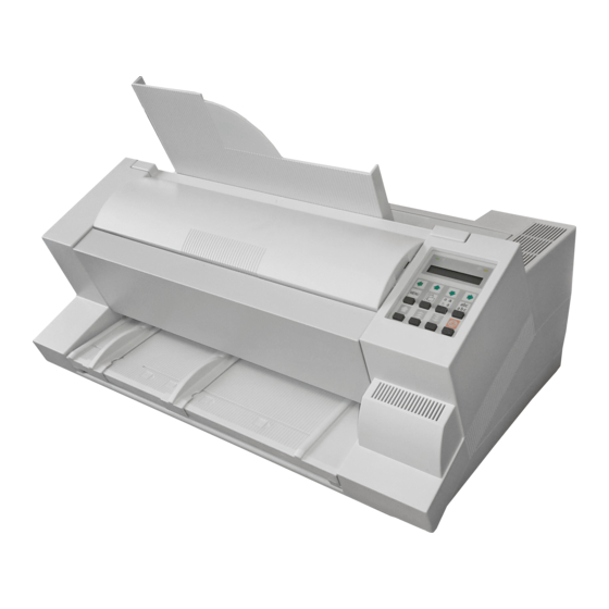
LA600 MultiPrinter
Field Service Manual
Order No.: ER-LA600-SV
The information in this document is subject to change without notice and should not be construed as
a commitment by Digital Equipment Corporation. Digital Equipment Corporation assumes no
responsibility for any errors that may appear in this document.
Copyright © by Digital Equipment Corporation 1994.
All rights strictly reserved. Reproduction or issue to third parties in any form is not permitted without
written authorization from the publisher.
Pub. No. 5112 991 12932
November 1994
Advertisement
Table of Contents

Related Manuals for Digital Equipment MultiPrinter LA600


Summary of Contents for Digital Equipment MultiPrinter LA600
- Page 1 Field Service Manual The information in this document is subject to change without notice and should not be construed as a commitment by Digital Equipment Corporation. Digital Equipment Corporation assumes no responsibility for any errors that may appear in this document.
-
Page 2: Table Of Contents
Printer Engine LA600 ........3-4... -
Page 3: Safety Precautions
LA600 Field Service Manual Safety Precautions Some of the maintenance procedures described in this section require that the printers top housing is removed. This exposes the internal working parts of the printer. During operating some of these parts are potentially dangerous. -
Page 4: Preventive Actions For Keeping The Printer Running
LA600 Field Service Manual Preventive Actions for Keeping the Printer Running The following points should be additionally checked on a service call. Item Problem Remedial Action Platen Paper feeding problems Remove platen and clean surface thoroughly using platen cleaner S/CP 09. -
Page 5: Procedures For Removal And Reassembly
LA600 Field Service Manual LA600 Field Service Manual Procedures for Removal and Reassembly Part: Housing DEC P/N: FD-W03RF-01 Part No: 5112 292 38200 This chapter describes the removal procedures which are necessary for proper handling of the spare parts and subunits of the printer. - Page 6 LA600 Field Service Manual LA600 Field Service Manual Part: Printer Engine LA600 DEC P/N: 29 31790-01.A01 Part No: 5112 292 62901 REMOVAL Set the printer into "LOCAL MODE" Disconnect the system interface cable Remove the ribbon cartridge Switch the printer off and disconnect the mains cable ⇒...
-
Page 7: Psu-40A Assy
LA600 Field Service Manual LA600 Field Service Manual Part: PSU-40A Assy DEC P/N: FD-W02BY-01 Part No: 5112 292 38110 REMOVAL Disconnect mains cable Remove all encasing parts (see Part: Housing) Loosen the two screws (A) securing the PSU-40A assy ⇒... -
Page 8: Dev-40 La600 Assy
Loosen the two screws (A) and remove screw (B) ⇒ Remove the DEV-40 LA600 Assy a) while removing, DEV-40 LA600 assy (K) is automatically disconnected from CU-40 LA600 assy (C) b) disconnect all plug connections from the DEV-board: - plug (D) - Page 9 Part No: 5112 292 62991 REMOVAL Disconnect mains cable Remove all encasing parts (see Part: Housing) Remove DEV-40 LA600 Assy (see Part: DEV-40 LA600 Assy) ⇒ Remove if plugged in memory card (A) ⇒ Remove the Personality Module after loosing the two lockscrews (B) ⇒...
- Page 10 Part No: 5112 208 07590 REMOVAL Disconnect mains cable Remove all encasing parts (see Part: Housing) Remove DEV-40 LA600 Assy (see Part: DEV-40 LA600 Assy) Remove CU-40 LA600 Assy (see Part: CU-40 LA600 Assy) ⇒ Exchange the EEPROM CU-40-00 (D)
-
Page 11: Operator Panel
LA600 Field Service Manual LA600 Field Service Manual Part: Operator Panel DEC P/N: FD-W00CU-01 Part No: 5112 292 38150 REMOVAL Disconnect mains cable Remove all encasing parts (see Part: Housing) ⇒ Disconnect Operating Panel cable (A) ⇒ Loosen the screw (B) located at the bottom of the Operating Panel ⇒... -
Page 12: Power On/Off Switch Assy
LA600 Field Service Manual LA600 Field Service Manual Part: Power ON/OFF Switch Assy DEC P/N: FD-W02B3-01 Part No: 5112 292 38820 REMOVAL Disconnect mains cable Remove all encasing parts (see Part: Housing) Remove PSU-40A Assy (see Part: PSU-40A Assy) ⇒... -
Page 13: Cable Print Head Assy
Disconnect the colour option, if installed, incl.connector f) Disconnect cable (E) from the interface connection board g) Disconnect the print head cable from DEV-40 LA600 Assy h) Remove the two plastic clips (F) i) Remove the print head cable... -
Page 14: Encoder Strip Assy
LA600 Field Service Manual LA600 Field Service Manual Part: Encoder Strip Assy DEC P/N: FD-W0417-01 Part No: 5112 292 37970 REMOVAL Disconnect mains cable Remove all encasing parts (see Part: Housing) ⇒ Remove the two screws (A) (Detail Y) ⇒... -
Page 15: Kit Lubrication Felt
LA600 Field Service Manual LA600 Field Service Manual Part: Kit Lubrication Felt DEC P/N: 29-31804-01. A01 Part No: 5112 270 04541 REMOVAL Disconnect mains cable Remove all encasing parts (see Part: Housing) Remove Encoder Strip Assy (see Part: Encoder Strip Assy) -
Page 16: Print Head H-Encoder 40A
LA600 Field Service Manual LA600 Field Service Manual Part: Print Head H-Encoder 40A DEC P/N: FD-W0290-01 Part No: 5112 292 43100 REMOVAL Disconnect mains cable Remove all encasing parts (see Part: Housing) Remove encoder strip Assy (see Part: Encoder Strip Assy) -
Page 17: Horizontal Motor 40A
REMOVAL Disconnect mains cable Remove all encasing parts (see Part: Housing) Remove DEV-40 Assy (see Part: DEV-40 LA600 Assy) ⇒ a) Disengage the drive belt (A) from the drive wheel of the horizontal motor by pressing the belt tension element (B),... -
Page 18: Carriage 40A Assy
REMOVAL Disconnect mains cable Remove all encasing parts (see Part: Housing) Remove DEV-40 Assy (see Part: DEV-40 LA600 Assy) Remove the encoder strip Assy (see Part Encoder Strip Assy) Remove operator panel, but leave the interface cable connected (see Part: Operator Panel) -
Page 19: Protection Shield
LA600 Field Service Manual LA600 Field Service Manual Part: Protection Shield DEC P/N: FD-W041W-01 Part No: 5112 292 38390 REMOVAL Disconnect mains cable Open top cover Remove Ink Ribbon Remove Platen ⇒ Dismount protection shield (B) by loosening the two screws (A). - Page 20 Part No: 5112 292 63840 REMOVAL Disconnect mains cable Remove all encasing parts (see Part: Housing) Remove DEV-40 Assy (see Part: DEV-40 LA600 Assy) ⇒ Locate the Ribbon Gear 40B Assy (A) ⇒ a) Loosen the cable (F) from the cable guide...
-
Page 21: Rep. Kit Ribbon Gear
Part No: 5112 292 41091 REMOVAL Disconnect mains cable Remove all encasing parts (see Part: Housing) Remove DEV-40A Assy (see Part: DEV-40 LA600 Assy) ⇒ Locate the Ribbon Gear 40B Assy (A) ⇒ a) Loosen the cable (F) from the cable guide... -
Page 22: Stepping Motor 7.5 Deg (Platen Gap Control)
Part No: 5112 209 24460 REMOVAL Disconnect mains cable Remove all encasing parts (see Part: Housing) Remove DEV-40A Assy (see Part: DEV-40 LA600 Assy) ⇒ Disconnect the four pin motor cables from the motors plug ⇒ Remove the two screws (B) fixation of the stepper motor Warning: Do not loosen the screw (A). -
Page 23: Stepping Motor 1.8 Deg (Vertical Paper Transport)
Part No: 5112 292 62411 REMOVAL Disconnect mains cable Remove all encasing parts (see Part: Housing) Remove DEV-40 Assy (see Part: DEV-40 LA600 Assy) ⇒ Remove the motor cable guide from the DEV-40 Assy ⇒ Remove the four pin motor cable (A) from the cable guide ⇒... -
Page 24: Tractor Gear 40A
REMOVAL Disconnect mains cable Remove all encasing parts (see Part: Housing) Remove DEV-40 Assy (see Part: DEV-40 LA600 Assy) ⇒ a) The paper path for output must be set to tractor. By moving the carriage to the uppermost right position the paper path will be changed (an audible "click") -
Page 25: Stacker Elements 40B Assy
Part No: 5112 292 40990 REMOVAL Disconnect mains cable Remove all encasing parts (see Part: Housing) Remove DEV-40 Assy (see Part: DEV-40 LA600 Assy) ⇒ Loosen the two screws (A) securing the Power ON/OFF switch and put it away ⇒... - Page 26 LA600 Field Service Manual LA600 Field Service Manual Part: Print Head LA600 DEC P/N: 29-31807-01. A01 Part No: 5112 292 62761 Removal of the print head (5) Caution: print head may be very hot immediately after printing! Lift and remove the output stacker (1)
- Page 27 LA600 Field Service Manual LA600 Field Service Manual Installing the new print head (5) Ensure that the printer is switched OFF. For print head installation, the carriage should be aligned with the cut-out on the paper guide plate (green insert).
-
Page 28: Paper Run/In Detector Assy
LA600 Field Service Manual LA600 Field Service Manual Part: Paper Run/In Detector Assy DEC P/N: FD-W04JJ-01 Part No: 5112 292 38050 REMOVAL Disconnect mains cable Remove all encasing parts (see Part: Housing) ⇒ Remove circlip (A) and bearing (B). The axle falls down ⇒... - Page 29 LA600 Field Service Manual LA600 Field Service Manual Part: Kit Pressure Roll FF1 DEC P/N: 29-31801-01. A01 Part No: 5112 292 41080 REMOVAL Disconnect mains cable Remove all encasing parts (see Part: Housing) Remove the encoder strip Assy (see Part: Encoder Strip Assy) ⇒...
-
Page 30: Minipitch Belt Stepper
Part No: 5112 200 08790 REMOVAL Disconnect mains cable Remove all encasing parts (see Part: Housing) Remove DEV-40 Assy (see Part: DEV-40 LA600 Assy) ⇒ a) Locate the right side of the form feed shaft for exchanging b) Remove both minipitch belts (B) -
Page 31: Kit Belt Pulley 40A
Part No: 5112 292 49210 REMOVAL Disconnect mains cable Remove all encasing parts (see Part: Housing) Remove DEV-40 Assy (see Part: DEV-40 LA600 Assy) ⇒ a) Locate the right side of the form feed shaft for exchanging b) Remove both minipitch belts (B) - Page 32 Part No: 5112 292 38460 REMOVAL Disconnect mains cable Remove all encasing parts (see Part: Housing) Remove DEV-40 Assy (see Part: DEV-40 LA600 Assy) Remove stacker elements Assy (see Part: Stacker Elements 40B Assy) ⇒ a) Locate the gearwheel (B), remove the circlip (C) and the...
-
Page 33: Kit Tractor 40A
LA600 Field Service Manual LA600 Field Service Manual Part: Kit Tractor 40A DEC P/N: FD-W02M8-01 Part No: 5112 292 38470 REMOVAL Disconnect mains cable Remove all encasing parts (see Part: Housing) Snap out the paper supports (C) ⇒ a) Locate the bearing (A) and (B) on the left side of the printer... -
Page 34: Kit Belt Tension 40A
LA600 Field Service Manual LA600 Field Service Manual Part: Kit Belt Tension 40A DEC P/N: FD-W02M5-01 Part No: 5112 292 38480 REMOVAL Disconnect mains cable Remove all encasing parts (see Part: Housing) Remove the print head ⇒ a) Disengage the drive belt (A) from the drive wheel horizontal motor by pressing the belt tension elements on pos. - Page 35 LA600 Field Service Manual LA600 Field Service Manual Part: Kit ASF Lever DEC P/N: FD-W04B7-01 Part No: 5112 292 22480 REMOVAL ⇒ Remove the AFS-Cassette from the printer and remove any paper loaded, and the paper support (if mounted). ⇒...
-
Page 36: Kit Torsion Spring D-Axis
LA600 Field Service Manual LA600 Field Service Manual Part: Kit Torsion Spring D-Axis DEC P/N: 29-31803-01. A01 Part No: 5112 292 41070 REMOVAL Disconnect mains cable Remove all encasing parts (see Part: Housing) ⇒ Remove lever (A) from D-axis (the plastic snap-in will be destroyed) ⇒... -
Page 37: Kit Screws And Springs
LA600 Field Service Manual LA600 Field Service Manual Part: Kit Screws and Springs DEC P/N: FD-W05RK-01 Part No: 5112 292 38490 Location of Screws and Springs 11 Spring 0.6x4x23 ST F. Paper Run 12 Spring 0.3x4.5x20 ST Ribbon Gear 13 Spring Carriage Axis... - Page 38 LA600 Field Service Manual 18 Spring Tractor Exit 20 Torsion Spring Tractor Gear 21 Spring Manual Front Insertion 22 Cable clip 23 Springs for Print Head Fixation 24 Holder right/left (green) 25 Bearing Platen (green) Digital Equipment Corporation Page 3-67...
-
Page 39: Wearing Parts
LA600 Field Service Manual LA600 Field Service Manual 4 Wearing Parts Part: Platen Assy DEC P/N: LA60X-PN Part No: 5112 292 38010 This chapter describes the removal procedures which are necessary for proper handling of the wearing parts of the printer. - Page 40 LA600 Field Service Manual LA600 Field Service Manual To install the Platen Assy (2) Ensure that the printer is switched OFF. ⇒ Place platen (2) in the vacant space between print head and metal bar. ⇒ Move print head from its right hand position into the centre.
-
Page 41: Asf Pick-Up Rollers
LA600 Field Service Manual LA600 Field Service Manual Part: ASF Pick-up Rollers DEC P/N: LA60X-PR Part No: 5112 292 41000 To Remove the ASF Pick-up Rollers (62) ⇒ Remove the ASF cassette (30) from the printer by drawing back the release lever (63), releasing the mounting lugs. - Page 42 LA600 Field Service Manual LA600 Field Service Manual To install the Pick-up Rollers (62) ⇒ Slide the new pick-up rollers (62) onto the bar (65). ⇒ Insert the free end of the bar into its mounting, ensuring that each roller flange (67) is positioned so that they mate with the slots (68) in the paper sleeves.
- Page 43 LA600 Field Service Manual Digital Equipment Corporation Page 4-9 Page 4-10 Digital Equipment Corporation...
-
Page 44: List Of Spares And Repairs
LA600 Field Service Manual LA600 Field Service Manual 5 List of Spares and Repairs Item Part No. Digital Part No. Type Kit Lubrication Felt 5112 270 04541 29-31804-01.A01 Item Part No. Digital Part No. Type Kit Press Roll FF1 5112 292 41080 29-31801-01.A01...
Need help?
Do you have a question about the MultiPrinter LA600 and is the answer not in the manual?
Questions and answers