
Related Manuals for Digital Equipment LA75 plus companion


Summary of Contents for Digital Equipment LA75 plus companion
- Page 1 LA75 Plus Companion Printer Installation and User Guide Digital Equipment Corporation...
- Page 2 First Printing, July 1991 The information in this document is subject to change without notice and should not be construed as a commitment by Digital Equipment Corporation. Digital Equipment Corporation assumes no responsibility for any errors that may appear in this document.
- Page 3 FCC NOTICE This equipment generates and uses radio frequency energy and if not installed and used properly, that is, in strict accordance with the manufacturer’s instructions, may cause interference to radio and television reception. It has been type tested and found to comply with the limits for a Class B computing device in accordance with the specifications in Subpart J of Part 15 of FCC Rules, which are designed to provide reasonable protection against such interference in a residential installation.
-
Page 5: Table Of Contents
Contents Preface ........... . . viii 1 Installing the Printer Checking the Contents of the Box . - Page 6 3 Loading the Paper Paper Controls ........3–1 Loading Paper .
- Page 7 Service ..........7–1 Digital Equipment Corporation Services ....7–1 Calling the Service Center .
- Page 8 C–16 ISO Latin-Cyrillic Supplemental Character Set ....C–28 C–17 ISO Latin-2 Supplemental Character Set ....C–29 C–18 JIS Katakana Character Set .
-
Page 10: Preface
Preface About This Guide The LA75 Plus Companion Printer Installation and User Guide is part of the LA75 Plus documentation package. This guide, which explains how to install and operate the printer. is written for someone with little or no computer experience. -
Page 11: Conventions Used In This Guide
Chapter 7, Reference Information contains general user reference material, including a summary of the printer’s set-up features, and printer and paper specifications. Appendix A, Set-up contains details of the set-up process, and a complete list of the available values for each of the printer’s features. The factory setting of each feature is marked. -
Page 12: Software Requirements
The other guides in the LA75 Plus documentation package are the LA75 Plus Companion Programmer Reference Manual, part number EK–LA75S–RM–001, and the LA75 Plus Companion Printer Sheet Feeder Guide, part number EK–LA75S–SF–001. The optional Automatic Sheet Feeder is documented separately in the LA75 Plus Companion Printer Sheet Feeder Guide. -
Page 13: About The Printer
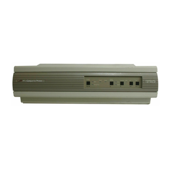
About the Printer The LA75 Plus is a narrow-carriage, impact dot-matrix printer, designed to be a personal desk-top printer, and suitable for general business applications. It has flexible paper handling, and is capable of printing on continuous pinfeed paper, single sheets, multiple-part forms, and envelopes. An Automatic Sheet Feeder (LA75Y-SF) is available as an option, to hold and automatically load up to 80 sheets of cut paper. -
Page 15: Installing The Printer
Installing the Printer 1.1 Checking the Contents of the Box Unpack the LA75 Plus and make sure you have all the items shown in the table. If any items are missing or damaged, contact your Digital sales representative. Please complete the installation procedure in sequence. After you install the LA75 Plus, keep this guide near the printer for easy reference. - Page 16 1–2 Installing the Printer...
-
Page 17: Site Considerations
1.2 Site Considerations The LA75 Plus can be installed in your office, school, or home. Environmental Conditions Install the printer in an area away from a heater or other heat source, and away from an air conditioner or strong drafts. Avoid installing the printer in a dusty or humid environment. -
Page 18: A First Look At The Printer
1.3 A First Look at the Printer Before installing the LA75 Plus, spend a little time familiarizing yourself with the printer. Item Number Item Name Access Cover Tractor Release Lever Paper Release Lever Printhead Adjustment Lever Control Panel Printhead Paper Parking Lever Paper Cover Bail Bar Parallel Port... - Page 19 Installing the Printer 1–5...
-
Page 20: Installing The Power Cord
1.3.1 Installing the Power Cord Make sure the power switch is set to 0 (off). Plug the power cord into the socket at the back of the printer. Plug the other end of the cord into your electrical outlet. 1–6 Installing the Printer... -
Page 21: Removing The Packing Material
1.3.2 Removing the Packing Material Remove the access cover. Remove the cardboard packing. Installing the Printer 1–7... -
Page 22: Installing The Ribbon Cartridge
1.3.3 Installing the Ribbon Cartridge Note: The printer will automatically detect a color ribbon as soon as one has been installed. Remove the ribbon cartridge from its wrapper. To tighten the ribbon, turn the ribbon adjustment knob in the direction indicated on the cartridge. 1–8 Installing the Printer... - Page 23 Fit the ribbon cartridge between the mounting clips (C) on the carriage. Make sure the ribbon fits between the front of the printhead (B) and the clear plastic smudge guard (A). Press down on the cartridge until you hear it click into place. Note: Make sure the ribbon is secured on both the left and right sides.
- Page 24 Turn the ribbon adjustment knob enough to tighten the ribbon against the printhead. 1–10 Installing the Printer...
-
Page 25: Testing The Printer
1.4 Testing the Printer The printer self-test allows the printer to check its operations independently. To load paper into the printer and run the self-test, perform the following steps: Make sure the power switch is set to 0 (off). Remove the access cover and the paper cover. Installing the Printer 1–11... - Page 26 Unlock only the clamp on the right tractor by pulling the clamp towards the front of the printer. Note: The left tractor has been factory set so that the left edge of the paper (column 1) lines up correctly with the printhead when it starts printing.
- Page 27 Align the pinfeed holes on both edges of the paper with the tractor pins. Close the tractor doors to secure the paper. Note: The red marks on the bail bar indicate the print area for a standard sheet of paper. Use these marks to help position the paper correctly. Readjust the right tractor position by moving it to the right so that the paper extends smoothly between the two tractors.
- Page 28 Pull the paper release lever towards the front of the printer to set the printer in tractor mode. Replace the access cover and the paper cover. Note: The printer will not work if the covers are not on, or if they are replaced incorrectly.
- Page 29 On the control panel, press and hold down the Form Feed switch (FF), and turn the power switch to 1 (on). Note: The paper is fed through automatically, so do not turn the platen knob. Only turn the platen knob to manually clear a paper jam. 10 Release the Form Feed switch as soon as the printer begins to print.
-
Page 30: Connecting The Printer To A Computer System
1.5 Connecting the Printer to a Computer System A. Connecting to a Digital Computer, Server, or Terminal You should connect to the serial port before following the steps described in this section. B. Connecting to a Digital PC or PC Compatible You should connect to the parallel port, and select the IBM Proprinter X24E driver from the PC application software before following the steps described in this section. - Page 31 Turn the power switch to 0 (off). Plug the interface cable into the back of the printer. To connect to a Digital PC or PC Compatible, use the parallel data cable BC-19M-10. If you use a shielded serial data cable (DD-16E-10), insert it into the cable retainer. Installing the Printer 1–17...
- Page 32 Plug the other end of the interface cable directly into your host computer. If you use an adapter, first plug the interface cable into the appropriate adapter, and then to your host computer or video terminal (with printer port). To connect to a Digital Computer, Server, or Terminal, use the H8571-A adapter. 1–18 Installing the Printer...
-
Page 33: Cables
1.5.1 Cables For specific information on cables, see Section 7.6 in Chapter 7. 1.5.2 Printing a File Refer to your computer system documentation for information about operating the printer with your computer. Your computer or terminal may require printer set-up before it can operate with the printer. If your computer does not require printer set-up, you can print a file as follows: Turn your computer or video terminal on. -
Page 34: If You Have Difficulties Printing A File
1.5.3 If You Have Difficulties Printing a File The LA75 Plus configuration is factory set for use with Digital’s computer systems. If you have difficulties printing your files correctly, you may need to change the printer’s configuration. Some suggestions follow. Check that the printer features match the host computer configuration, in particular, the communication protocol. -
Page 35: Using The Operator Control Panel
Using the Operator Control Panel 2.1 About the LA75 Plus Control Panel This chapter describes how to use the printer’s operating controls. To print files, the control panel switches perform the functions that appear above the switches. Ready Quiet/ Fault Quiet Protocol Quality... -
Page 36: Printer Operating Switches And Indicators
2.1.1 Printer Operating Switches and Indicators Ready Indicator and Switch The Ready switch puts the printer on-line or off-line. When the Ready indicator (RDY) lights up, the printer is on-line and ready to print. When the Ready indicator is blinking, the printer is off-line and will not print. If you press the Ready switch while the printer is printing (putting it off-line), the LA75 Plus will complete the line it is printing, stop, then move the paper until the last line is visible. - Page 37 Quiet/Quality Switch When the printer is in Ready mode, pressing the Quiet/Quality switch puts it into Quiet mode. When the printer is off-line, (the Ready indicator (RDY) is blinking), the Quiet/Quality switch allows you three choices of print quality: Letter Quality (LQ), which prints at 83 characters per second (CPS). Draft Quality (DQ), which prints at 250 CPS.
-
Page 39: Loading The Paper
Loading the Paper 3.1 Paper Controls The levers and controls described in this section are used for loading and positioning paper in the printer. Loading the Paper 3–1... - Page 40 3–2 Loading the Paper...
- Page 41 Parking Lever The parking lever (7) controls the autopark function. This function is used to move pinfeed paper into the park position before single-sheet loading. Bail Bar The bail bar (5) holds the paper against the platen (9). The red marks (6) on the bail bar indicate the print area for a standard sheet of paper.
- Page 42 Printhead Adjustment Lever The printhead adjustment lever changes the printhead position to allow for different thicknesses of paper, and for forms or envelopes. The lever can be moved to four positions to vary the distance between the printhead and the platen.
-
Page 43: Loading Paper
Loading Methods and Types of Paper Method Type of Paper Rear Loading (Section 3.2.1) Pinfeed Paper Single-sheet Loading (Section 3.2.2) Single Sheets/Envelopes Bottom Loading (Section 3.2.4) Pinfeed Paper -Labels/Multipart See also the LA75 Plus Companion Printer Sheet Feeder Guide Loading the Paper 3–5... - Page 44 . and Diagram C the Bottom Pinfeed Loading method. The three methods are discussed respectively in Section 3.2.1, Section 3.2.2 and Section 3.2.4 later in this chapter. See also the LA75 Plus Companion Printer Sheet Feeder Guide 3–6 Loading the Paper...
-
Page 45: Rear Loading
3.2.1 Rear Loading Unlock only the clamp on the right tractor by pulling the clamp towards the front of the printer. Note: The left tractor has been factory set so that the left edge of the paper (column 1) lines up correctly with the printhead when it starts printing. - Page 46 Note: The red marks on the bail bar indicate the print area for a standard sheet of paper. Use these marks to help position the paper correctly. Readjust the right tractor position by moving it to the right so that the paper extends between the two tractors.
- Page 47 Pull the paper release lever towards the front of the printer to set the printer in tractor mode. Loading the Paper 3–9...
- Page 48 Replace the access cover and the paper cover. Pull out the wire paper-separator (A). Note: The printer will not work if the covers are not on, or if they are replaced incorrectly. 3–10 Loading the Paper...
- Page 49 Activating the Automatic Paper Feed You can now advance the paper to the print position by activating the automatic paper feed as follows. Turn the power switch to 1 (on). All the indicators light up on the Control Panel. The printhead moves to the center, to the print position, and the paper automatically moves under the platen, also to the print position.
-
Page 50: Viewing The Last Printed Line
3.2.1.1 Viewing the Last Printed Line This section and Section 3.2.1.2 describe two LA75 Plus features that are available using the Rear Loading method. There are three methods to advance the paper to see the last printed line. (This procedure applies only to pinfeed paper.) To ease readability, the paper support should be in the raised position. -
Page 51: Document On Demand
3.2.1.2 Document on Demand If the last character received by the printer was a Form Feed, or if you pressed FF at the end of the last printed job, you can make use of the Document on Demand feature and so avoid wasting paper before the next printed job. -
Page 52: Single-Sheet Loading
3.2.2 Single-sheet Loading Turn the power switch to 1 (on). All indicators light up on the Control Panel. The printhead moves to the center, to the print position. If (and only if) there is pinfeed paper in the printer, pull the parking lever all the way forward to the autopark position. - Page 53 Raise the paper support and secure it in place. Pull out the paper separator. Loading the Paper 3–15...
- Page 54 Move the paper release lever towards the back of the printer so that it is in friction mode. Place a single sheet of paper on the paper support so that the paper is resting just under the platen. If the Fault indicator goes out when the paper is inserted, move the paper away from the platen until the Fault indicator lights up again.
-
Page 55: Printing Multiple Single Sheets
Advance the paper to the print position by activating the Automatic Paper Feed. To do this, press the FF switch on the control panel. The Fault Indicator turns off. You are now ready to print on the single sheet. 3.2.2.1 Printing Multiple Single Sheets To print multiple single sheets, use the Automatic Sheet Feeder option. -
Page 56: Switching To Bottom Loading
3.2.3 Switching to Bottom Loading Note: Using the printer’s bottom slot requires a special printer table or stand. Contact your Digital sales representative for ordering information. Make sure the power switch is set to 0 (off). Remove the access cover and the paper cover. Move the left tractor release lever towards the front of the printer until it locks. - Page 57 Move the right tractor release lever towards the front of the printer and pull the tractor unit up. The tractors are now in a horizontal position. Loading the Paper 3–19...
- Page 58 Unlock the tractor clamp on the right tractor by pulling the clamp towards the front of the printer. Note: The left tractor has been factory set so that the left edge of the paper (column 1) lines up correctly with the printhead when it starts printing.
- Page 59 Move the paper release lever towards the front of the printer to set the printer in tractor mode. Loading the Paper 3–21...
-
Page 60: Bottom Loading
3.2.4 Bottom Loading After opening the tractor doors, insert the paper through the bottom slot of the printer. Note: To prevent skewing, position the paper so that it feeds straight into the bottom of the printer. Note: Using the printer’s bottom slot requires a special printer table or stand. - Page 61 Align the pinfeed holes on both edges of the paper with the tractor pins of both tractors. Close the tractor doors to secure the paper. Note: The red marks on the bail bar indicate the print area for a standard sheet of paper.
- Page 62 Adjust the paper by pulling it down from beneath the printer’s bottom slot. 3–24 Loading the Paper...
- Page 63 Manually adjust the top of the form. Replace the access cover and the paper cover. Note: The printer will not work if the covers are not on, or if they are replaced incorrectly. You are now ready to print. Note: To return to rear loading, release the tractor unit by pulling both tractor release levers towards the front of the printer.
-
Page 64: Adjusting The Printhead For Paper Thickness
3.3 Adjusting the Printhead for Paper Thickness For single-part pinfeed paper, and single-sheet hand-fed paper: Push the printhead adjustment lever all the way towards the platen. For multipart paper or envelopes: Pull the lever towards the front of the printer. 3–26 Loading the Paper... -
Page 65: Using Fonts
Using Fonts This chapter describes how to insert and access the optional font cartridges available for the LA75 Plus. 4.1 Using the Optional Font Cartridges A set of font cartridges is available which cover different printing needs. Each cartridge works both in DEC and Emulation protocols. For details of these cartridges see Section 7.6 in Chapter 7. - Page 66 Insert the cartridge, making sure it is firmly in place. Caution: The font cartridge has a key and can be inserted only one way. Do not try to force the cartridge into place. Power On the printer and enter the user set-up mode to select the type style or character sets provided by the cartridge.
-
Page 67: Configuring The Printer
Configuring the Printer 5.1 What is Configuration? This chapter describes how to set up or configure the LA75 Plus, so that the printer and your computer system can communicate correctly with each other. Communication between the two requires that both the computer operating system and the printer have the same communication settings or features. -
Page 68: Determining The Printer's Configuration
5.1.1 Determining the Printer’s Configuration Check your computer system’s documentation to determine what your system requirements are for protocol, baud rate, and data bits and parity. (These are, respectively, Generic Features 1, 7, and 8 in Set-up.) You can see what is programmed into your LA75 Plus’s set-up memory by following these instructions: Turn the power switch to 0 (off). -
Page 69: Features And Values
5.2 Features and Values Each of the LA75 Plus’s features stored in its set-up memory has at least two values. (See Section 7.4 in Chapter 7). A value is an option or choice within each feature. The features are organized into three groups as follows: Generic DEC (specific to Digital protocol) X24 (specific to IBM Proprinter X24E) -
Page 70: Set-Up Mode Switches And Indicators
5.3 Set-up Mode Switches and Indicators In set-up mode, the control panel performs the functions that appear in letters and arrows below the switches. Set-up Switch To put the printer in set-up mode, press the Set-up switch while turning the printer on. -
Page 71: Saving New Values And Exiting Set-Up Mode
Note the following: If the first value Protocol is set to DEC, only the DEC and Generic group features are accessible in Step 3. If the first value Protocol is set to X24, only the X24 and Generic group features are accessible in Step 3. If the communication is port-dependant, all features are accessible. -
Page 73: Maintaining The Printer
Maintaining the Printer 6.1 General Maintenance The printer does not need preventive maintenance. The casing of the printer and the platen will need cleaning from time to time. Digital’s computer-accessories catalog, DECdirect, lists suitable cleaners for these tasks. Always use the cleaners in accordance with the instructions on the cleaners.. Paper Select the correct kind of paper for the job. -
Page 74: Correcting Simple Problems
6.2 Correcting Simple Problems This section lists possible fault symptoms and suggests tests and actions to help you clear those symptoms. How to Use This Section Find the category in which your problem occurs. For example, if the print appears very light on the paper, look at Section 6.2.4, Print-related Problems. -
Page 75: No Printout
If you have an Automatic Sheet Feeder, ensure that its front cover is seated correctly. Closing it and pressing the Ready switch should light up the Ready indicator. When the power is On, the carriage does not move. Make sure that the access cover is seated correctly. 6.2.2 No Printout Printing does not start. -
Page 76: Operation-Related Problems
6.2.3 Operation-related Problems Power/Ready indicator is flashing; Fault indicator is On. This is an "out of paper" response. Make sure that the tractor/friction feed lever is in the position needed by your application. Load paper; the Fault indicator will turn Off, and the Power/Ready indicator will either turn On or flash. -
Page 77: Print-Related Problems
6.2.4 Print-related Problems Printer cannot print in color. Check that the color ribbon (LA75R-KC) is installed. Check that the proper control sequences are sent to the printer. (See the English-language Appendix C.) Font cartridge has been installed, but the printer is still using internal Courier fonts. -
Page 78: Ribbon Or Carriage-Related Problems
Characters printed at a slant; paper tears or jams. Make sure that the paper release lever is set fully to the front or to the rear and not in an intermediate position. Examine the paper pathway; remove any obstructions. Is the paper too loose or too taut between the tractors? If the holes in the paper are deformed at their outer edges, the paper is too taut. -
Page 79: Removing And Replacing The Ribbon Cartridge
6.3 Removing and Replacing the Ribbon Cartridge Remove the printer access cover. Move the printhead carriage to the center of the platen. Caution: Only use Digital’s LA75 Plus ribbons (LA75R-KA or LA75R-KC). Do not use LA75 ribbons (LA50R-O6) as this could reduce the life of the printhead. - Page 80 Push the ribbon cartridge notches outward and remove the ribbon cartridge by pulling it upwards. Discard the old ribbon cartridge. 6–8 Maintaining the Printer...
- Page 81 Turn the ribbon adjustment knob on the new cartridge in the direction indicated. Maintaining the Printer 6–9...
- Page 82 Fit the ribbon cartridge between the mounting clips (C) on the carriage. Make sure that the ribbon fits between the front of the printhead (B) and the clear plastic smudge guard (A). Press down on the cartridge until you hear it click into place. Note: Make sure that the ribbon is secured on both the left and right sides.
- Page 83 Tighten the ribbon with the ribbon adjustment knob. Replace the access cover. Maintaining the Printer 6–11...
-
Page 84: Removing And Replacing The Fuse
6.4 Removing and Replacing the Fuse Note: Turn the power switch to 0 (off). Disconnect the power cord from the wall outlet and the printer. Push the fuse holder in while turning it to the left, and remove it. Caution: Replace the old fuse with a new one of equal value. 6–12 Maintaining the Printer... -
Page 85: Reference Information
If you cannot correct a problem with the printer, contact your Digital sales representative. 7.2 Digital Equipment Corporation Services Digital Equipment Corporation provides a wide range of maintenance programs that cover small systems, terminals, and printers. These include on-site, carry- in, and mail-in maintenance services. You can use these programs to select a plan that meets your service needs, from complete Digital support to self-maintenance. -
Page 86: Calling The Service Center
7.3 Calling the Service Center Refer to the following advice before calling the service center. Before calling for service, check Check Section 6.2 in Chapter 6; you may be able to the problem yourself. solve the problem yourself. Who should call for service? Typically, the system manager should place the call for service. - Page 87 Number Feature Factory-set Value Generic 1 Protocol at Power-up Port Dependant Generic 2 Form Length 11 inches Generic 3 Vertical Pitch 6 LPI Generic 4 Automatic Advance Not Selected Generic 5 Print Quality Control Software Control Generic 6 Port Selection Automatic Generic 7 Baud Rate...
-
Page 88: Specifications
7.5 Specifications Printer Specifications Feature Range Printing Method: Impact Dot Matrix, 24 pin Print Head: 24 wires @ 180 dots per inch vertical density Sensors: Print head position Cover open Paper out Paper edge Parking lever pulled Automatic Sheet Feeder present Protocols: Digital’s Conformance Level-2 (for sixel graphics) IBM Proprinter (X24E) - Page 89 Feature Range Inches Selectable Form 76.2 Length: 88.9 101.6 139.7 152.4 177.8 203.2 215.9 279.4 296.16 11 2/3 304.8 355.6 (0.176):XXX (1/180"):XXX Other values are available by software selection. Horizontal Print 5 CPI 10 CPI (80 col) Density: 6 CPI 12 CPI 6.6 CPI 13.2 CPI...
- Page 90 Feature Range Character Sets: US ASCII DEC Hebrew Great Britain DEC Turkish DEC Finland DEC Turkish Supplemental France DEC Greek Supplemental DEC French/Canada DEC Supplemental Germany DEC Technical Italy Katakana JIS Roman DEC Hebrew Supplemental DEC Norway/Denmark VT100 Spain W.P. Legal DEC Sweden ISO Latin 1 Supplemental Norway/Denmark...
- Page 91 Feature Range Dimensions: Width= 400 mm (15.7"), Depth = 290 mm (11.4"), Height = 120 mm (4.8"), Height with Auto Sheet Feeder = 400 mm (15.7") Weight: 16 pounds (7,5 kg) Power Requirements: 100 V @ 1.6 Amps, 50/60 Hz, 50 W 120 V @ 1.6 Amps, 50/60 Hz, 50 W 220 V @ 1.0 Amps, 50/60 Hz, 50 W 240 V @ 1.0 Amps, 50/60 Hz, 50 W...
- Page 92 Paper Specifications Feature Range Paper Types: Pinfeed (tractor media) Single sheets Up to 3 part forms Envelopes Continuous Paper (Tractor Media): Single part continuous paper between 4" and 10" wide including perforations is supported. The allowable weight for these forms is 56 to 90 g/m² (15 to 24 pounds per ream).
-
Page 93: Printer Accessories
7.6 Printer Accessories Description Part Number Ribbon Cartridges Black Ribbon Cartridges (six in a box) LA75R-KA Color Ribbon Cartridges (six in a box) LA75R-KC Font Cartridges Letter Gothic Font LA75Y-CA Orator Font LA75Y-CB Prestige Elite Font LA75Y-CC OCR A Font LA75Y-CD OCR B Font LA75Y-CE... - Page 94 Interface/System Cable and Adapters Connector Type Adapter and Cable 25-Pin Male VAXstation 3200/3500 H8571-A and BC16E VT100 Series H8571-A and BC16E DECserver 200/MC (DSRVB-AA) H8571-A and BC16E CCITT V.24/CCITT V.28 H8571-A and BC16E 9-Pin Male VT200-Series H8571-B and BC16E DECmate H8571-B and BC16E Pro-Series H8571-B and BC16E...
-
Page 95: A Set-Up
Set-up A.1 Set-up Mode Set-up mode enables you to customize the printer for your specific use. This appendix contains a full list of the choices you can make for each feature of the printer. To change any of the features, perform the following steps: Load the fanfold paper Enter the Set-up mode Select the feature to be changed... -
Page 96: Set-Up Features And Values - Common Features For Both Dec And Ibm Protocols
Table A–1 Set-up Features and Values - Common Features for both Dec and IBM protocols Number Feature Value Generic 1 Protocol at Power-up IBM Proprinter Port Dependent (Serial=DEC, Parallel=IBM) * Generic 2 Form Length 3 inches 3.5 inches 4 inches 5.5 inches 6 inches 7 inches... - Page 97 Table A–1 (Cont.) Set-up Features and Values - Common Features for both Dec and IBM protocols Number Feature Value Generic 3 Vertical Pitch 2 lines per inch 3 lines per inch 4 lines per inch 6 lines per inch * 8 lines per inch 12 lines per inch 1 line per cm...
- Page 98 Table A–1 (Cont.) Set-up Features and Values - Common Features for both Dec and IBM protocols Number Feature Value Generic 7 Baud Rate 1200 2400 4800 * 9600 Generic 8 Data Bits and Parity 7-Even 7-Odd 7-Space 7-Mark 8-Even 8-Odd 8-None * Generic 9 Buffer Control...
- Page 99 Table A–1 (Cont.) Set-up Features and Values - Common Features for both Dec and IBM protocols Number Feature Value Generic 10 Error Beep One Beep * Three Beeps Continuous Generic 11 Typestyle Internal * Cartridge Generic 12 Input Buffer Size 8 K * 32 K - No DLL Capability Generic 13...
- Page 100 Table A–2 Set-up Features and Values - Dec Protocol Features Number Feature Value DEC 1 Horizontal Pitch 5 characters per inch 6 characters per inch 6.6 characters per inch 8.25 characters per inch 8.55 characters per inch 9 characters per inch 10 characters per inch (80 col) 12 characters per inch 13.2 characters per inch...
-
Page 101: Set-Up Features And Values - Dec Protocol Features
Table A–2 (Cont.) Set-up Features and Values - Dec Protocol Features Number Feature Value DEC 2 G0 Character Set U.S. ASCII * Great Britain DEC Finland France DEC French Canada Germany Italy JIS Roman DEC Norway/Denmark Spain DEC Sweden Norway/Denmark DEC Dutch DEC Swiss DEC Portugal... - Page 102 Table A–2 (Cont.) Set-up Features and Values - Dec Protocol Features Number Feature Value VT100 W.P. Legal User Preference character set SPECIAL Cartridge character sets labelled with (External) The SPECIAL character set is reserved for future use. The cartridge character sets are listed if a font cartridge with additional DEC character sets is installed.
- Page 103 Table A–2 (Cont.) Set-up Features and Values - Dec Protocol Features Number Feature Value DEC 3 User Pref. Character Set DEC Supplemental * ISO Latin 1 supp. Katakana ISO Hebrew supp. DEC hebrew supp. DEC Hebrew DEC Technical ISO Latin 5 supp. ISO Latin-Greek supp.
- Page 104 Table A–2 (Cont.) Set-up Features and Values - Dec Protocol Features Number Feature Value DEC 5 Text Mode Right Margin Truncate Wrap * DEC 6 Auto LF on CR Selected Not Selected * DEC 7 Auto CR on LF Selected Not Selected * DEC 8 Disconnect on EOT...
- Page 105 Table A–3 Set-up Features and Values - IBM Protocol Features Number Feature Value X24 1 Slashed Zero Zero with slash Without slash * X24 2 Auto LF on CR Selected Not Selected * X24 3 Auto CR on LF Selected Not Selected * X24 4 Active character table...
-
Page 106: Set-Up Features And Values - Ibm Protocol Features
Table A–3 (Cont.) Set-up Features and Values - IBM Protocol Features Number Feature Value X24 5 National character set U.S.A (Code Page 437) * Multilingual (Code Page 850) Portugal (Code Page 860) Norway (Code Page 865) Spain (Code Page 220) Greece (Code Page 210) Canada-French (Code Page 863) -
Page 107: Set-Up Features And Values - Factory Setting
Table A–3 (Cont.) Set-up Features and Values - IBM Protocol Features Number Feature Value X24 8 Horizontal Pitch 5 Characters per inch 6 Characters per inch 8.55 Characters per inch 10 Characters per inch * 12 Characters per inch 17.1 Characters per inch Proportional Prop. - Page 109 Printing Control Characters Use this mode to assist when debugging software. Exceptions: In this mode, control characters are printed, not acted upon, with the following exceptions. Line Feed character produces a carriage return and line feed action, as well as printing <LF>...
- Page 110 The control character acronyms are included in this appendix. Procedure: With paper loaded, press the linefeed switch (LF), and switch power On. To terminate this mode, switch power Off. B–2 Printing Control Characters...
-
Page 111: Positioning Controls
DEC PPL2 Quick Reference This appendix contains basic information on the DEC PPL2 commands that are supported in the LA75 Plus. It also contains the character set code tables supported by the LA75 Plus in the DEC PPL2 protocol. The commands are listed by function in the following order: Positioning controls Sheet size and margins Type size and spacing, managing implicit cursor motion... - Page 112 The following conventions are used in the command listings: Table C–1 Conventions Escape (1/11), introduces an escape sequence Control Sequence Introducer (9/11), introduces a control sequence. CSI can also be represented by the equivalent escape sequence ESC [ (1/11 5/11). Device Control String (9/0), introduces a device control string.
- Page 113 Table C–2 (Cont.) Positioning Controls DECVTS Vertical Tab Set ESC 3 Horizontal Position Pn = position to move to CSI Pn ` Absolute Horizontal Position Pn = number of columns CSI Pn a Relative down Vertical Position Pn = position to move to CSI Pn d Absolute Vertical Position...
- Page 114 Table C–4 (Cont.) Type size and spacing, managing implicit cursor motion DECSHORP Set Horizontal Ps = 0: Determined by current font CSI Ps w Pitch Ps = 8: 8.25 CPI Ps = 1: 10 Ps = 9: 15 CPI Ps = 11: 17.1 CPI Ps = 2: 12 CPI Ps = 12: 8.55 CPI Ps = 3: 13.2 CPI...
-
Page 115: Tabs
Table C–5 (Cont.) Font management and attribute selection Select Graphic Rendition Ps = 0: Turn off all attributes CSI Ps m - Selecting Attributes Ps = 1: Bold on Ps = 3: Slant on Ps = 4: Underline on Ps = 9: Strike-through on Ps = 21: Double underline on Ps = 22: Bold off Ps = 23: Slant off... -
Page 116: Selecting Character Sets
Table C–7 Selecting character sets ASCEF Announce Subset ASCII in G0 and GL. ESC SP L of Code Extension ISO Latin-1 in G1 and GR. Facilities Same as ESC SP L ESC SP M ASCII in G0 and GL. ESC SP N DECAUPSS Assign User Ps = 0: 94-char. -
Page 117: Character Sets Power-Up Settings
Figure C–1 Designating and Invoking Character Sets Invoking or LS2 LS1R "Invoking" Sequences or LS3 Locking Shift, Single Shift, LS2R or Announcers LS3R Announcer Sequences "Designating" Sequences (SCS) or Announcers Selecting 94-Char 96-Char Graphic Graphic Repertory Repertory DECAUPSS User Preference M L O - 0 0 3 9 7 6 Table C–8 Character Sets Power-up Settings... -
Page 118: Reports
Table C–8 (Cont.) Character Sets Power-up Settings Character Set Power-up Setting US ASCII G2 and G3 User Preference Character Set User Preference Character Set Defined by Set-up feature "DEC 3" Table C–9 Reports Device Request Device Attributes Report CSI c Attributes Device Ps1 = 72... -
Page 119: Miscellaneous
Table C–10 Miscellaneous DECSCL Select Conformance Ps = 0: reset - native level CSI Ps1 " p Level Ps = 71: reset - DEC PPL1 Ps = 72: reset - DEC PPL2 DECSTR Soft Terminal Reset Reset to initial state CSI ! p Reset to Initial State Reset to initial state... -
Page 120: Scs Final Characters
Table C–10 (Cont.) Miscellaneous SnC1R C1 Transmit Process 7-bit, drop 8th bit ESC SP 6 /DEC*C1 /Receive Process 7-bit and 8-bit ESC SP 7 Transmit 8-bit as 7-bit equivalents ESC SP F Transmit 8-bit (not supported) ESC SP G DECBAR Start or Stop Bar Start Barcode CSI % SP 0... - Page 121 Table C–11 (Cont.) SCS Final Characters F Designator Character Set Characters Code Legal 2/5, 3/4 JIS Katakana JIS Roman 4/10 DEC Norwegian/Danish ISO Spanish 5/10 DEC Swedish DEC Swiss 3/13 Norwegian/Danish ‘ DEC Supplemental 2/5, 3/5 DEC Technical > 3/14 DEC Special Graphics DEC Portuguese 2/5, 3/6...
- Page 122 Figure C–2 Standard 8-bit Code Table (Left Half) Standard Left C0 Control Set Graphics Left (GL) Column (XON) " (XOFF) & < > ASCII Graphic Character Set LEGEND Column/Row Octal Decimal MLO-003973 C–12 DEC PPL2 Quick Reference...
-
Page 123: C–3 Standard 8-Bit Code Table (Right Half)
Figure C–3 Standard 8-bit Code Table (Right Half) Standard Right C1 Control Set Graphics Right (GR) Column µ DEC Supplemental Graphic Character Set LEGEND 12/1 Column/Row Octal Decimal MLO-003974 DEC PPL2 Quick Reference C–13... -
Page 124: National Replacement Character Sets
The following tables provide the list the positions from the National Replacement Character (NRC) Sets which differ from the U.S. ASCII Character Set. All other positions of these NRC sets are the same as in the U.S. ASCII character set. Table C–12 National Replacement Character sets National Replacement Character Sets... - Page 125 Table C–12 (Cont.) National Replacement Character sets National Replacement Character Sets Location Norwegian- Norwegian- ASCII Danish Spanish Swedish Danish Dutch Swiss Portuguese 7/12 ø ñ ö ø ö ç 7/13 å ç å å ¼ ü õ 7/14 ü ü ’...
- Page 126 Figure C–4 DEC Special Graphics Character Set DEC Special Graphics Character Set GL GR GL GR GL GR GL GR GL GR GL GR Column 360 Row SCAN 3 SCAN 5 " SCAN 7 SCAN 9 & π < > SCAN 1 LEGEND GL GR...
-
Page 127: C–5 Dec Technical Character Set
Figure C–5 DEC Technical Character Set DEC Technical Character Set GL GR GL GR GL GR GL GR GL GR GL GR Column 360 Row Π π Ψ α ψ β ρ Σ χ σ δ τ ε Φ φ Γ... - Page 128 Figure C–6 ISO Latin-1 Supplemental Character Set ISO Latin-1 Supplemental Character Set GL GR GL GR GL GR GL GR GL GR GL GR Column 360 Row NBSP LEGEND 12/1 Column/Row Octal Decimal MLO-004000 C–18 DEC PPL2 Quick Reference...
-
Page 129: C–7 Legal Character Set
Figure C–7 Legal Character Set Legal GL GR GL GR GL GR GL GR GL GR GL GR Column 360 Row " & < > LEGEND GL GR 12/1 Column/Row Octal Decimal MLO-003982 DEC PPL2 Quick Reference C–19... - Page 130 Figure C–8 DEC 7-bit Hebrew Character Set DEC 7-Bit Hebrew Character Set GL GR GL GR GL GR GL GR GL GR GL GR Column 360 Row " & < > LEGEND GL GR 12/1 Column/Row Octal Decimal MLO-004001 C–20 DEC PPL2 Quick Reference...
-
Page 131: C–9 Dec Hebrew Supplemental Character Set
Figure C–9 DEC Hebrew Supplemental Character Set DEC Hebrew Supplemental Character Set GL GR GL GR GL GR GL GR GL GR GL GR Column 360 Row µ LEGEND GL GR 12/1 Column/Row Octal Decimal MLO-004002 DEC PPL2 Quick Reference C–21... - Page 132 Figure C–10 ISO Latin-Hebrew Supplemental Character Set ISO Latin-Hebrew Supplemental Character Set GL GR GL GR GL GR GL GR GL GR GL GR Column 360 Row NBSP µ LEGEND 12/1 Column/Row Octal Decimal MLO-004003 C–22 DEC PPL2 Quick Reference...
-
Page 133: C–11 Iso Latin-Greek Supplemental Character Set
Figure C–11 ISO Latin-Greek Supplemental Character Set ISO Latin-Greek Supplemental Character Set GL GR GL GR GL GR GL GR GL GR GL GR Column 360 Row ι Π υ π NBSP Α Ρ α ρ Β β ς Γ Σ... - Page 134 Figure C–12 DEC Greek Supplemental Character Set DEC Greek Supplemental Character Set GL GR GL GR GL GR GL GR GL GR GL GR Column 360 Row ι υ Α Π α π Β Ρ β ρ Γ Σ γ σ...
-
Page 135: C–13 Iso Latin-5 Supplemental Character Set
Figure C–13 ISO Latin-5 Supplemental Character Set ISO Latin-5 Supplemental Character Set GL GR GL GR GL GR GL GR GL GR GL GR Column 360 Row NBSP β LEGEND 12/1 Column/Row Octal Decimal MLO-006611 DEC PPL2 Quick Reference C–25... - Page 136 Figure C–14 DEC Turkish 7-bit Character Set DEC Turkish 7-bit Character Set GL GR GL GR GL GR GL GR GL GR GL GR Column 360 Row " < > LEGEND GL GR 12/1 Column/Row Octal Decimal MLO-006605 C–26 DEC PPL2 Quick Reference...
-
Page 137: C–15 Dec Turkish 8-Bit Supplemental Character Set
Figure C–15 DEC Turkish 8-bit Supplemental Character Set DEC Turkish 8-bit Supplemental Character Set GL GR GL GR GL GR GL GR GL GR GL GR Column 360 Row µ β LEGEND GL GR 12/1 Column/Row Octal Decimal MLO-006606 DEC PPL2 Quick Reference C–27... -
Page 138: Iso Latin-Cyrillic Supplemental Character Set
Figure C–16 ISO Latin-Cyrillic Supplemental Character Set ISO Latin-Cyrillic Supplemental Character Set GL GR GL GR GL GR GL GR GL GR GL GR Column 360 Row Α Ρ ρ Ν NBSP δ Β Τ Β Τ Γ Γ Γ Γ... -
Page 139: Iso Latin-2 Supplemental Character Set
Figure C–17 ISO Latin-2 Supplemental Character Set ISO Latin-2 Supplemental Character Set GL GR GL GR GL GR GL GR GL GR GL GR Column 360 Row NBSP LEGEND GL GR 12/1 Column/Row Octal Decimal MLO-006608 DEC PPL2 Quick Reference C–29... -
Page 140: Jis Katakana Character Set
Figure C–18 JIS Katakana Character Set JIS Katakana GL GR GL GR GL GR GL GR GL GR GL GR Column 360 Row LEGEND GL GR 12/1 Column/Row Octal Decimal MLO-003983 C–30 DEC PPL2 Quick Reference... -
Page 141: Conventions
IBM Proprinter X24E Quick Reference This appendix contains basic information on the Proprinter X24E Emulation commands supported in the LA75 Plus. It also contains the character set code tables supported by the LA75 Plus in Proprinter X24E Emulation mode. This guide should be used in conjunction with the Digital Ansi-compliant Printing Protocol Level 2 Programming Reference Manual and the Digital Ansi-compliant Printing Protocol Level 2 Programming Supplement. -
Page 142: Control Characters
Table D–2 Control Characters Location Control in Character in Character Character Set 1 (A) Set 2 (B) Description Null 0/7 or 8/7 Beeper 0/8 or 8/8 Backspace 0/9 or 8/9 Horizontal Tab 0/10 or 8/10 0/10 Line Feed 0/11 or 8/11 0/11 Vertical Tab 0/12 or 8/12... - Page 143 Table D–3 (Cont.) Terminal Management Escape Sequence Description Stop Printing ESC j Reset Printer to DEC mode ESC [ ! p Set Initial Condition ESC [ K n1 n2 init id P1 P2 Code-Page Switching. ESC [ T n1 n2 NUL NUL P1 P2 Pn1 Pn2 for Code-Page number, most-significant byte first.
-
Page 144: Vertical Form Handling
Table D–4 (Cont.) Vertical Form Handling Escape Sequence Description Set Automatic Perforation Skip on fanfold paper ESC N Pn Pn is the number of lines from bottom of paper to skip Cancel Automatic Perforation Skip ESC O ESC [ n n1 n2 P1 P2 P3 P4 Set Vertical Units P1 P2 for Text vertical units value, P3 P4 for Graphic vertical units value... - Page 145 Table D–5 (Cont.) Horizontal Form Handling and Printing Modes Escape Sequence Description Select Print Mode ESC I Pn Pn = 0/0: Draft, 10 cpi Pn = 0/2: LQ, 10 cpi Pn = 0/3: Proportional, 10 cpi Pn = 0/4: Downloaded Draft, 10 cpi Pn = 0/6: Downloaded LQ, 10 cpi Pn = 0/7: Proportional Downloaded LQ, 10 cpi Pn = 0/8: Draft, 12 cpi...
-
Page 146: Print-Mode Priority Chart
Table D–5 (Cont.) Horizontal Form Handling and Printing Modes Escape Sequence Description Select Color Printing ESC r Pn Pn = 0/0: Black Pn = 0/1: Magenta Pn = 0/2: Cyan Pn = 0/3: Blue Pn = 0/4: Yellow Pn = 0/5: Red Pn = 0/6: Green Select Yellow Printing ESC y... -
Page 147: Alternate Graphics Mode (Agm)
Table D–7 (Cont.) Graphics Modes Escape Sequence Description High Resolution Graphics ESC [ g n1 n2 v1 ... vn First parameter v1 is for Mode Table D–8 Alternate Graphics Mode (AGM) Escape Sequence Description Graphics Line spacing (AGM) , 180/Pn lines per inch ESC 3 Pn Set Text Line spacing (AGM) , 60/Pn lines per inch... -
Page 148: Character Set Selection
Table D–9 (Cont.) Character Set Selection Escape Sequence Description Downloading Printer Characters ESC = n1 n2 ID v1 ... vn ID = 2/3 D–8 IBM Proprinter X24E Quick Reference... -
Page 149: All Character Set, All Code-Pages, Left Side
Figure D–1 All Character Set, All Code-pages, Left Side IBM All Character Set (1) Column " & < > LEGEND Column/Row Octal Decimal MLO-004008 IBM Proprinter X24E Quick Reference D–9... -
Page 150: All Character Set, Code-Page 437 U.s.a. , Right Side
Figure D–2 All Character Set, Code-page 437 U.S.A. , Right Side IBM All Character Set (1B) Column 360 Row α β Γ Π Σ σ µ τ Φ Θ Ω δ φ ε LEGEND 12/1 Column/Row Octal Decimal MLO-004009 D–10 IBM Proprinter X24E Quick Reference... -
Page 151: All Character Set, Code-Page 850 Multilingual, Right Side
Figure D–3 All Character Set, Code-page 850 Multilingual, Right Side Column Ç É á Ó ± ü æ í ß é Æ ó Ê Ô â ô ú Ë Ò ä ö ñ È õ ¶ à ò Ñ Á ı...
Need help?
Do you have a question about the LA75 plus companion and is the answer not in the manual?
Questions and answers