
Subscribe to Our Youtube Channel
Related Manuals for Digital Equipment LA310


Summary of Contents for Digital Equipment LA310
- Page 1 LA310 MultiPrinter Service Guide Order Number: ER-LA310-SG.001 digital equipment corporation maynard, massachusetts...
- Page 2 October 1992 The information in this document is subject to change without notice and should be construed as a commitment by Digital Equipment Corporation. Digital Equipment Corporation assumes no responsibility for any errors that may appear in this document. © Digital Equipment Corporation 1992.
-
Page 3: Fcc Notice
FCC NOTICE This equipment generates and uses radio frequency energy and if not installed and used properly, that is, in strict accordance with the manufacturer's instructions, may cause interference to radio and television reception. It has been type tested and found to comply with the limits for a Class B computing device in accordance with the specifications in Subpart J of Part 15 of FCC Rules, wich are designed to provide reasonable protection against such interference in a residential installation. - Page 4 COMPLIANCE STATEMENT TO THE CANADIAN DEPARTMENT OF COMMUNICATIONS Radio Act Registration SOR/88-475 This digital apparatus does not exceed the Class B limits for radio noise emissions from digital apparatus as set out in the radio interference regulations of the Canadian Department of Communications.
-
Page 5: Table Of Contents
CONTENTS Overview Identification Recommended Tools Installation Preparation 2.1.1 Precautions and Suggestions 2.1.2 Unpackaging and Preliminary Operations Installation Paper Loading 2.3.1 Paper 2.3.2 Printable Area 2.3.2 Paper Handling Devices Set-up Set-up Mode Switches and Indicators 3.1.1 Entering Set-up Mode 3.1.2 Printing the Printer's Current Configuration 3.1.3 Changing the Printer's Configuration 3.1.4... - Page 6 Service Tests 4.4.1 Printing Self Test 4.4.2 LA310 MultiPrinter Service Test 4.4.3 Serial Port Loopback Self Test 4.4.4 Parallel Port Loopback Self Test Troubleshooting General Rules Fault Isolation Fault Correction 5.3.1 Power-Related Problems 5.3.2 Operation-Related Problems 5.3.3 Print-Related Problems 5.3.4 Ribbon or Carriage-Related Problems...
- Page 7 Appendix Set-up Configuration C.1.1 Set-up Directory C.1.2 General Main Menu C.1.3 Protocol Selection Main Menu C.1.4 Communications Main Menu C.1.5 DEC PPL2 Main Menu C.1.6 IBM PP III Main Menu C.1.7 Epson FX-1050 Main Menu Appendix General Block Diagram DC/AC Power Supply BA 298 Board D.3.1 I/O Signal General Description D.3.2 CPU and EPROM-SRAM-E2PROM Memories...
-
Page 8: Overview
The LA310 is produced in three voltage models to meet all worldwide voltage require- ments. The LA310 allows the user to select either HSD, NLQ1, NLQ2 or Quiet print mode. In Quiet Mode acoustic noise is reduced to a minimum. -
Page 9: Identification
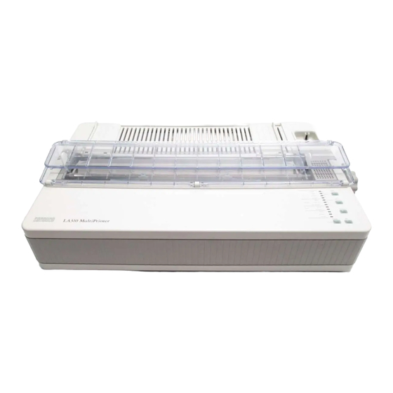
1.1 Identification Table 1-1 A First Look at the Printer Item Number Item Name Rear cover (paper support) with guides Paper Selection Lever Platen Knob Operator Control Panel Prop (for holding paper support in sloping position) Push tractor Paper present switch on tractor Power cord socket Electrical data plate Ruler... - Page 10 LA 310 - Service Manual...
-
Page 11: Recommended Tools
1.2 Recommended Tools You are recommended to use the following tools: Table 1-1 Recommended tools Part Number Description 29-26106-00 50 Hz Terminal Tool Kit 29-26109-00 60 Hz Terminal Tool Kit 12-25083-01 MMJ Loopback Connector 29-27887-01 Parallel Loopback Connector 29-11762-00 Antistatic Kit... -
Page 12: Installation
INSTALLATION 2.1 Preparation 2.1.1 Precautions and Suggestions For correct functioning of the printer, the following precautions should be taken: - Do not install the printer near to sources of heat or exposed to direct sun light. - Leave a free area around the printer to allow sufficient ventilation for the printer electronics. -
Page 13: Installation
2.2 Installation Note: You should refer to the LA 310 Printer Installation and User's Guide to get more detailed information for the installation of the printer and loading of paper. 1. Unpack the LA 310 and inspect the contents for missing items or damage. The contents are: the printer, user documentation, ribbon cartridge, power cord and serial interface cable. - Page 14 6. Make sure that the label on the back of the printer quotes the same voltage as that available from the wall socket. 7. Connect the power cable first to the printer and then to the wall socket. DO NOT SWITCH ON 8.
- Page 15 Fig 2.3 Installing the Cartridge 9. Do not connect the data cable to the host system. 10. Run the print test. The print test is activated from a printer OFF condition, once you have loaded a sheet of paper, switch the printer off. Then,holding down the QUIET key on the operator console, switch the printer on again.
-
Page 16: Paper Loading
2.3 Paper Loading 2.3.1 Paper The printer can handle a wide range of paper types. The printable area will depend on the type of paper used. Both single sheets and continuous stationery can be used alone or with carbon or chemical copies; max. combination: original + 4 copies (see note). The paper weight of single sheets may vary from 60 to 100 g/m . - Page 17 The following table contains the dimensions and weight of the paper which can be used on your printer PAPER DIMENSIONS WEIGHT COPIES/ COMPOSITION Single Width: 2 to 18 in 60 - 100 g/m Original only sheet (50 - 457.2 mm) 80 - 100 g/m Length: 2.5 to 21 in (63.5 - 533 mm)
-
Page 18: Printable Area
2.3.2 Printable Area The maximum printable area on the page is illustrated in the followings diagrams. It will vary according to the type of paper used. SINGLE SHEETS DIMENSIONS CONTINUOUS STATIONERY 457.2 mm P (Paper feed path width) 454.4 mm 420 mm M (Max. -
Page 19: Paper Handling Devices
2.3.3 Paper Handling Devices Use the following devices and manual controls on your printer to load and feed paper: - Paper guides on the rear paper support - Paper feed knob - Paper selection lever - Bail bar - Ruler - Print head distance lever - Internal sprocket ( Push Tractor ) - Operator console... - Page 20 Paper Feed Knob With the printer in PAUSE state, use the paper feed knob to advance/retract paper and to remove jammed paper. Fig. 2.5 Paper Feed Knob Paper Selection Lever Position this lever towards the front of the printer if you are using single sheets. Set it towards the rear of the printer if you are using continuous stationery.
- Page 21 Internal Sprocket ( Push Tractor ) This device feeds single or multicopy continuous stationery. An optional external sprocket ( Pull Tractor ) can be installed to ease heavy paper feeding. Fig. 2.8 Push Tractor External Sprocket ( Pull Tractor ) The optional pull tractor is required if the heavier types of multicopy continuous statio- nery are used and is mandatory if a paper composition consisting of an original plus four copies is used.
- Page 22 Print Head Distance Lever Use this lever to vary the distance between the print head and the platen. The distance will depend on the thickness of the paper you are using and/or the number of copies being printed. The lever has seven positions. Fig.
- Page 23 The following table illustrates the relation-ship between the lever position and the number of copies. LEVER NUMBER OF COPIES THICKNESS max. (mm) POSITION Needle wear recovery 0.125 Original copy 0.125 Original + 1 copy 0.200 Original + 2 copies 0.280 Original + 3 copies 0.360 Original + 4 copies...
- Page 24 Bail Bar The bail bar holds the paper against the platen as it is fed through the printer. When loading any paper, check that the rollers on the bail bar are positioned correctly for the loading operation. They must be positioned in the grooves on the bail bar as follows: Width of paper used...
- Page 25 Ruler The ruler, embossed on the printer bodywork between the platen and the push sprocket, simplifies horizontal alignment of the paper and the guides on the paper support. Fig. 2.12 Ruler Note: The on the ruler marks the position of the paper present photocell. 2-14...
-
Page 26: Set-Up
SET-UP When you enter Set-up mode, the Set-up Directory menu is displayed. From the Set-up Directory menu, you can enter the Main Menu for each option that is displayed on the Set-up Directory menu. At each main menu there are several levels of submenus. At each main menu or submenu, the item that was selected prior to entering this menu is printed in bold type, and the red triangle of the printhead is automatically positioned underneath the item. -
Page 27: Set-Up Mode Switches And Indicators
3.1 Set-up Mode Switches and Indicators There are five buttons on the operator control panel that perform functions in Set-up mode. Normal mode Set-up mode function function Set-up function Ready Set-up Enter/Exit Set-up mode → Quiet/Quality Next Item ↓ LF/Protocol Select item at cursor ←... -
Page 28: Entering Set-Up Mode
3.1.1 Entering Set-up Mode Digital recommends that you enter Set-up mode in tractor-feeding mode, and not cut sheet mode. NOTE: You must not run Set-up mode with the Pull Tractor option installed. To enter Set-up mode: Press and hold the Set-up switch while setting the power switch to ON (1). If you have put paper in the parking position and use tractor feeding, paper is loaded automatically. -
Page 29: Printing The Printer's Current Configuration
At the Set-up directory, Print is the initial default entry. Select PRINT by using ↓. The printer then prints its current settings. The factory-set configuration for the LA310 MultiPrinter begins printing as follows: This is the beginning of the configuration list that the printer prints. -
Page 30: Changing The Printer's Configuration
3.1.3 Changing the Printer's Configuration At each menu or submenu beyond the Set-up menu, the item that was selected prior to entering this menu is printed in bold type, and the red triangle on the print head is automatically positioned underneath the item. The symbol >... - Page 31 Using ← and → , move the cursor to GENERAL. Press ↓ to select the General menu. The entry GENERAL is underlined, and the first part of the General menu is displayed: As the error beep setting is not listed on that part of the menu, press → twice to move to the next line of the menu: The error beep setting is still not listed.
- Page 32 Press → to move to the error beep setting, and press ↓ to select it. The printer underlines ERROR BEEP and displays the error beep settings: The entry ONE BEEP is bolded as it is the default settings. Press → to move to the THREE BEEPS setting,and press ↓ to select it. The selected item is underlined, the printer enters in GENERAL menu, and the cursor points to the ERROR BEEP submenu: LA 310 - Service Manual...
-
Page 33: Saving New Values And Exiting Set-Up Mode
3.1.4 Saving New Values and Exiting Set-up Mode Pressing the Set-up switch once while in Set-up mode stores your set-up changes in the printer's memory, exits Set-up mode, and automatically returns the printer to print mode. NOTE: If you switch off the printer, or if the power is otherwise interrupted before you press the Set-up switch, no changes are stored in the printer's memory. -
Page 34: Error Conditions In Set-Up Mode
All indicators (except the Fault indicator) flash simultaneously. Use ← or → to move the cursor between the EPSON FX-1050 or CARTRIDGE setting. Press ↓ to select the setting you require. Use → to move to the MAIN SET-UP option, and press ↓ to move back to the Main Set-up menu. -
Page 35: Tests & Diagnostics
TESTS & DIAGNOSTICS 4.1 T & D Summary Table 4.1 provides the list of modes with the related front panel buttons that is to be depressed at power up in order to initiate each self-test,setting or test mode. Table 4.1: Self-tests, Set Modes and Test modes Front Panel Test Button(s)Pressed... -
Page 36: Power Up Diagnostic
4.2 Power up diagnostic Self test operations to check internal logic are performed automatically at power-up. Detected failures cause the Fault light to blink and the test to stop. The automatic diagnostics include the following tests: a ROM checksum test to verify all bits of ROM a RAM pattern test to exercise and verify all bits of RAM a NVR ( Non Volatile RAM ) checksum test all the control panel indicators remain on for 2 to 4 seconds. -
Page 37: Print Head Pattern Test
The adjustment setting can be changed by pressing the LF switch which causes the next number to be printed. Pressing the FF button will store the last selection and willl initiate the Printhead pattern test. Switch off to stop this test. 4.3.2 Print Head Pattern Test The printer is capable of executing a print head pattern which will allow Field Personnel to check the print head for individual needle wear. -
Page 38: Carriage Motion Test
4.3.4 Carriage Motion Test The printer is capable of executing a carriage motion self test which causes the printer to execute carriage motions and ribbon motions continuously. Detected failures cause the Fault light to blink. During this test, paper supply is not checked by the printer. When the cover is open, carriage motion stops. -
Page 39: Service Tests
adjustment and to save it in NVM. This adjustment is based on the type of paper used. Turn the printer off. NOTE: This adjustment may also be performed in friction mode. The setting saved in NVM during this operation is not reset by the FACTORY DFLT function available in the set-up mode. - Page 40 Each of the following tests shall not overlap the bottom of the form. When needed, the printer shall perform a form feed with the Last line printing and First line printing tests. Unless specified, all printed text shall be printed at 10 CPI, 6 LPI, Draft density, normal print mode.
-
Page 41: Serial Port Loopback Self Test
Carriage motion exerciser: 2 full cycles ( one cycle is: carriage movement from one end to the other and back ) Black boxes text : 3 one square-inch black boxes are printed in graphics mode. The 3 boxes are aligned horizontaly, the gap between each box is 1 inch. The graphics resolution is 120 dpi, horizontal and vertical. -
Page 42: Parallel Port Loopback Self Test
4.4.4 Parallel Port Loopback Self Test The printer is capable of testing the parallel port using the loopback connector as defined in Figure 4.1. The Parking and FF buttons must be depressed simultaneously before turning power- on and released after power-on initiate this test. The printer shall provide each output signal and check input circuits accordingly. -
Page 43: Troubleshooting
TROUBLESHOOTING 5.1 General Rules Learn about the problem. Talk to the operator who is using the equipment and probably knows more about the problem than anyone else. Examine the environment. Could it cause problems for the equipment? For example, is it very dirty or very hot? Identify the problem. -
Page 44: Fault Isolation
5.2 Fault Isolation The following sections list possible fault syntoms and give tests you can make and actions you can take to help to clear those syntoms. Table 5-1 indicates what problems are covered in this chapter and where you can find the relevant information. -
Page 45: Fault Correction
5.3 Fault Correction 5.3.1 Power-Related Problems No indicators on when power is switched on. 1. If the printer is functioning correctly but no indicators are on, replace the Console PCB assembly. 2. Test the power supply at the wall socket by relocating the printer or metering. If faulty, contact the responsible site engineer. - Page 46 At power on, the carriage does not move. 1. Make sure the access cover is seated correctly. 2. Logic may not be receiving the access cover switch signal. a. Make sure the connection between the operator panel and the Main Board is good. b.
- Page 47 No response to computer commands. READY indicator is on. 1. Examine the data cable connections. Reseat the data cable if necessary. 2. Check the condition of the data cable. Replace if damaged. 3. Run the printing self test. If this is not satisfactory, replace the Main Board. Run the loopback test.
-
Page 48: Operation-Related Problems
Single sheet paper does not advance. 1. Make sure the tractor/friction feed lever is set to friction feed. 2. The paper feed mechanism may be jammed or broken. Replace the Mechanical Assembly. 3. Replace the Main Board. 5.3.2 Operation-Related Problems LA 310 stops printing. - Page 49 6. Replace the Main Board. 7. Replace the Mechanical Assembly. Paper is not positioned at perforation for tear-off feature. 1. Make sure the printer is in the PAUSE state. If the READY indicator is on press the READY button. 2. If the platen has been moved by hand, reload the paper. Make sure you use a complete form for the first sheet.
-
Page 50: Print-Related Problems
5.3.3 Print-Related Problems Print faint or poor quality. 1. Is the paper thickness control set correctly for the paper you are using? Adjust if necessary. 2. Have you used the correct paper? chapter 2.3 contains a full specification of the paper you can use. - Page 51 4. Replace the Mechanical Assembly. 5. Replace the Main Board. Characters printed at a slant, Paper tears, Paper jams. 1. Make sure the tractor/friction feed lever is set fully to the front or to the rear and not in an intermediate position. 2.
-
Page 52: Ribbon Or Carriage-Related Problems
5.3.4 Ribbon or Carriage-Related Problems Ribbon Problems. 1. Make sure the ribbon is: a. Tensioned correctly. b. Not worn thin or dry. c. Not torn damaged in any other way. d. Not jammed. e. The correct type as recommended by Digital. 2. -
Page 53: Remove Replace
REMOVE REPLACE 6.1 General This chapter describes how to remove, replace and adjust major FRUs of the LA 310 MultiPrinter. Figure 6.1 shows the removal sequence of the Field Replacable Units. CONSOLE PLATEN PAPER GUIDE PULL TRACTOR RIBBON OVERLAY KNOB PANEL GROUP (OPTIONAL) PAPER SELECT... - Page 54 WARNING The procedures described in this chapter involve the removal of the system covers and should be performed by trained personnel only. ADVARSEL! Ifølge de procedurer, som er beskrevet i dette kapital, skal systemets beskyttelsesplader fjernes; dette bør kun udføres af personer der ved hvordan dette skal gøres.
- Page 55 ATTENZIONE La procedura descritta in questo capitolo comporta la rimozione delle coper- ture e deve essere eseguita solo da personale specializzato. ADVARSEL I dette kapitel beskrives bl. a. hvordan man fjerner dekslene rundt systemet. Dette arbeidet må bare utføres av fagfolk. AVISO Os procedimentos descritos neste capítulo respeitam à...
- Page 56 6.2 Printhead Remove and replace the printhead as follows. WARNING If the printer was recently used, the printhead may be hot. Be careful when handling the printhead. Open the top cover. Shift the carriage to the center of the platen. Remove the ribbon cartridge.
-
Page 57: Printhead-Platen Distance Adjustment
6.2.1 Printhead-Platen Distance Adjustment Open the top cover. Remove the paper and the ribbon. Set the paper thickness adjustment lever to position 1. Slacken off the printhead retaining screws (A). Using feeler gauges or the gauge supplied with the new printhead FRU, set the printhead-platen gap to 0.30 −... -
Page 58: Cover Replacement
6.3 Cover Replacement Put the paper selection lever in the friction mode position. Pull off the platen knob and the paper selection lever. Open the top cover, then push up to remove it. Rise the paper guide panel and pull up to remove it. Remove the two mounting screws (A), to remove the upper cover. -
Page 59: Internal Console Replacement
6.4 Internal Console Replacement Remove the top covers as shown in 6.3 Disconnect the control panel board connector from the main board. Installation: Install the console in reverse order of removal. CONNECTOR Figure 6.4 Disconnect the control panel board LA 310 - Service Manual... -
Page 60: Mechanical Assembly Replacement
6.5 Mechanical Assembly Replacement Remove the covers. Remove the operator console Lift up the mechanical assembly, and disconnect all connectors from the Main Board and remove printhead cable from the base. Installation: Install the mechanical assembly in reverse order of removal. Note:After mechanical assembly replacement, it is necessary to adjust the paper sensor (see page 4-4). -
Page 61: Printhead Cable Replacement
6.6 Printhead Cable Replacement Remove the mechanical assembly. Remove the printhead and unplug the head connector. Remove the printhead cable Installation: Install the printhead cable in reverse order of removal. Note: After printhead replacement it is necessary to adjust the distance between printhead and platen (see page 6-5). -
Page 62: Main Board Replacement
6.7 Main Board Replacement Remove the mechanical assembly. Unplug the power supply connector (1) from the board. Unscrew the three screws (2) to remove the Main Board. Installation: Install the Main Board in reverse order of removal. Note:After Main Board replacement, it is necessary to adjust the paper sensor (see page 4-4). -
Page 63: Power Supply Replacement
6.8 Power Supply Replacement Remove the mechanical assembly. Unplug the power supply connector (A) from the board. Unscrew the two screws (B and C) to disconnect the power supply from ground. Remove the power supply group by pulling on (D); then lift up it (E). Installation: Install the Power Supply in reverse order of removal. -
Page 64: Power Supply Fuse Replacement
6.9 Power Supply Fuse Replacement Remove the cover Unscrew the screws A, B and C. Lift up the cover D and replace the fuse. Note:Fuse rating: 630 mA for 220/240 V; 1.25 A for 120 V. Figure 6.9 Power Supply Fuse replacement 6-12... -
Page 65: Cleaning
CLEANING 7.1 Introduction The LA 310 has been designed as a low maintenance printer. Most of the maintenance needed is determined by the environment in which it operates. High ambient temperatures cause the oil on the paper moving mechanism and carriage to dry out.
Need help?
Do you have a question about the LA310 and is the answer not in the manual?
Questions and answers