Table of Contents
Advertisement
Advertisement
Table of Contents

Related Manuals for Loctite 97006


Summary of Contents for Loctite 97006
- Page 1 EQUIPMENT Operation Manual Digital Syringe Dispenser Part Number 97006...
- Page 2 START CONT X S 1 : S t a r t L o c t it e ( I r e la n in G c a t. e rm d ) L a n y n o .9 t d . 7 0 0...
-
Page 3: Table Of Contents
Contents Please observe the following Emphasized Sections Items Supplied For Your Safety Usage Description Displays, Operating Elements, and Connections Theory of Operation Functional Sequence 2.3.1 Time Controlled Mode 2.3.2 Continuous Mode Technical Data Energy Requirements 3.1.1 Electrics 3.1.2 Pneumatics Connections and Dimensions Other Data Installation Environmental Conditions... - Page 4 Contents Dispensing Filling the Syringe First Operation 5.2.1 Purging Air from the Syringe 5.2.2 Adjusting the Dispensed Quantity 5.2.2.1 Time Controlled Mode 5.2.2.2 Continuous Mode Changing the Syringe Shutdown Returning to Operation Care and Maintenance Care Maintenance Troubleshooting Documentation Pin Connections for Foot Switch Cable Accessories and Spare Parts Declarations of Conformity Declarations of Conformity...
-
Page 5: Please Observe The Following
Grey arrow = 2nd step White arrow = 3rd step Items Supplied 1 Digital Syringe Dispenser 97006 1 Power Cord 1 Foot switch 1 Needle Sample Kit 1 Instruction Manual 97006 As a result of technical development, the illustrations and descriptions in this instruction manual can... -
Page 6: For Your Safety
It is a self-contained dispenser system. The Loctite ® Digital Syringe Dispenser (97006) is designed for a product application position and for small quantities. With the Loctite ®... -
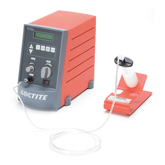
Page 7: Description
Description - Typical System Set-Up Displays, Operating Elements, and Connections Fold out the illustration inside the front cover! Digital Display Display of the dispensing time[s] for a dispensing sequence. – During dispensing in time controlled mode, the dispensing time remaining is indicated. –... - Page 8 Description - Typical System Set-Up Button Button for switching the measuring units for the dispensing pressure in the digital display. After each pressing of button , the indication of the selected dispensing pressure in the digital display changes to the other measuring unit [bar or psi] with the corresponding value. CONT Button Button for switching from time controlled mode to continuous mode.
- Page 9 Description - Typical System Set-Up Hose Clamp Syringe Air Line Adapter Assembly End Cap Adapter Plug Makes possible the clean emptying of the Syringe 15 and prevents the permeating of the product with air as well as the product running back out of the Syringe 15 into the control unit. Syringe Store filled syringes only with Luer-Lock tip caps 17 or end caps 13.
-
Page 10: Theory Of Operation
Digital Syringe Dispenser (97006) is connected to an external pneumatic supply. The Control Unit of 97006 regulates the adjusted dispensing pressure and controls the dispensing during the selected dispensing time. Pressure variations of more than 10 % result in an error message on the digital display (see Chapter 7). -
Page 11: Technical Data
2 bar (29 psi); max. 12 bar (174 psi) Quality Filtered 10 µm, oil-free, non-condensing If the required quality is not achieved, install a Loctite ® brand filter regulator. Accessory Order No. 985397 Regulation range of the pressure regulator 0.00 –... -
Page 12: Installation
– No splashing water Space Requirements 145 mm min 150 mm 260 mm 97006 Placement When the plug 14 is missing and the syringe 15 is handled in an improper manner, the product can enter and contaminate the control unit. -
Page 13: Basic Settings Of The Unit
Installation Basic Settings of the Unit Connecting the Unit Use only the cable and hose sets supplied. X S 1 : S ta L o c ti te M ad e in (I re Ge rm la n ca t.n d ) L an y o. -
Page 14: Dispensing
Dispensing Filling the Syringe If Loctite ® brand products are not properly handled, damage to health can result! Observe general safety regulations for the handling of chemicals! Observe manufacturer’s instructions! Request a safety data sheet for the product used! Close the tip of the syringe 15 with the Luer- Lock tip cap 17. -
Page 15: First Operation
Dispensing First Operation 5.2.1 Purging Air from the Syringe To avoid air bubbles during dispensing, the tip of the syringe must be purged of air. Hold the syringe 15 over a container since product will flow out! Switch the power switch 10 to the position I (ON). -
Page 16: Adjusting The Dispensed Quantity
Dispensing 5.2.2 Adjusting the Dispensed Quantity 5.2.2.1 Time Controlled Mode This mode of operation is used for spot shaped wetting or drop dispensing. With buttons , set the dispensing time to 0.50 s (factory setting). The indication of the dispensing time in the digital display begins blinking. -
Page 17: Continuous Mode
Dispensing 5.2.2.2 Continuous Mode This mode of operation is used for wettings of varying lengths or for the application of beads. With the pressure regulator 9, set the dispensing pressure to 0.50 bar (approx. 7 psi). An error message “P P r r e e s s s s . . 0 0 . . 8 8 3 3 N N O O K K ” with beeping is possible. -
Page 18: Changing The Syringe
Dispensing Changing the Syringe The unit need not be switched off to change the syringe. Press the hose clamp 11 closed so that pressure cannot be applied to the syringe adapter 12 as a result of an unintentional start. Replace the Luer-Lock tip cap 17 on the filled syringe 15 with a dispensing needle 16. Replace the syringe and release the hose clamp 11. -
Page 19: Shutdown
Dispensing Shutdown Switch the power switch 10 to the position O (OFF). Shutdown for Longer Periods of Non-use For pauses in the work of longer than 14 days, place the system out of operation to prevent curing of the product. Switch the power switch 10 to the position O (OFF). -
Page 20: Care And Maintenance
Recommended cleaning agents for: – Anaerobic, UV curing, and Chipbonder ® adhesives: Loctite ® brand cured adhesives cannot be removed with the solvents that are permitted to be used at the present time. Fluid adhesive residues can be removed with various solvents. -
Page 21: Troubleshooting
Troubleshooting Type of malfunction Possible causes Correction The digital display does not – No power voltage present. Check the power voltage. light. – Power switch 10 in position O (OFF). Switch power switch 10 to position I (ON). – Power fuse 23 is defective. Check/replace fuse 23. -
Page 22: Documentation
Troubleshooting Type of malfunction Possible causes Correction LED in button does – LED is defective. Contact Henkel Service. START CONT When the button is operational (check by not light. means of the digital display), the unit can be used until repaired by Henkel Service. –... -
Page 23: Accessories And Spare Parts
Accessories and Spare Parts Reference out the illustration inside the rear cover! Pos. No. Description Loctite Order No. 10 ml Air Line Adapters (2 pcs/box) .............97208 30 ml Air Line Adapters (2 pcs/box) .............97245 10 ml Clear Syringe Package (30 pcs/box) ...........97207 30 ml Clear Syringe Package (20 pcs/box) ...........97244... -
Page 24: Declarations Of Conformity
Declarations of Conformity Declarations of Conformity... -
Page 25: Warranty
Warranty WARRANTY Henkel expressly warrants that all products referred to in this Instruction Manual for (97006 Henkel Digital Syringe Dispenser) (hereafter called "Products") shall be free from defects in materials and workmanship. Liability for Henkel shall be limited, as its option, to replacing those Products which are shown to be defective in either materials or workmanship or to credit the purchaser the amount of the purchase price thereof (plus freight and insurance charges paid therefor by the user). - Page 26 31,8 mm 30,0 mm 12,7 mm 56,1 mm 38,6 mm...
- Page 27 Auburn Hills, Michigan 48326 São Paulo-Brazil Loctite and Chipbonder are registered trademarks of Henkel Corporation, U.S.A. © Copyright 2004. Henkel Corporation. All rights reserved. Data in this operation manual is subject to change without notice. Order Code No. 8950106USA...
Need help?
Do you have a question about the 97006 and is the answer not in the manual?
Questions and answers