Table of Contents
Advertisement
Quick Links
Advertisement
Table of Contents

Related Manuals for Loctite PULSE EQ RC50


Summary of Contents for Loctite PULSE EQ RC50
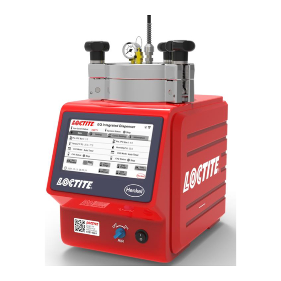
- Page 1 PULSE EQ RC50 Integrated Dispenser IDH 2814024 Operating Manual...
-
Page 2: Table Of Contents
Table of Contents Please Observe the Following ....................3 Emphasized Sections ......................3 For Your Safety ........................3 Unpacking and Inspection ....................4 Packing List ........................... 4 Features ..........................4 Field of Application (Intended Use) ................... 5 Description ........................... 6 2.1 Theory of Operation ........................ -
Page 3: Please Observe The Following
Care and Maintenance ......................31 Accessories and Spare Parts ....................32 Diagrams ............................ 33 Warranty ............................. 36 Declaration of Conformity ......................37 Please Observe the Following Emphasized Sections Warning! Refers to safety regulations and requires safety measures that protect the operator or other persons from injury or danger to life. -
Page 4: Unpacking And Inspection
Observe general safety regulations for the handling of chemicals such as ® Loctite adhesives and sealants. Observe the manufacturer’s instructions as stated in the Safety Data Sheet. While under warranty, the unit may be repaired only by an authorized Loctite service representative. Unpacking and Inspection ® Carefully unpack the Loctite EQ RC50 Integrated Dispenser I-4.0 and examine the... -
Page 5: Field Of Application (Intended Use)
Bluetooth, or Ethernet Field of Application (Intended Use) The Loctite EQ RC50 Integrated Dispenser I-4.0 combines both a controller and a reservoir into a single unit. The controller provides 2 independent digital timing channels that provide control of 2 pneumatic outputs. These outputs can be used to control any Loctite automatic dispense valve or pneumatic hand-held applicator. -
Page 6: Description
An uncovered bottle of Loctite product is placed directly into the EQ RC50 Integrated Dispenser I-4.0, the feedline is inserted into the product, and the reservoir lid is clamped in place. -
Page 7: Display, Operating Elements And Connections
2.2 Display, operating elements and connections Power Switch ON/OFF Air Pressure ON/OFF Switch UI Screen Valve Pressure Relief... -
Page 8: Technical Data
Reservoir Pressure Gauge Reservoir/Feedline Fitting Reservoir Knob x 3 Reservoir Lid Socket XS9 PLC Interface 10. Socket XS8 USB 11. ETHERNET 12. 24VDC Power In 13. Low Level Sensor 14. Silencer 15. Air Pressure In 16. Channel B ON Output 17. -
Page 9: Installation
Installation Before using the equipment for the first time check it carefully for signs of external damage. If any shipping damage is found DO NOT USE THE EQUIPMENT – return it to your supplier immediately. 4.1 Environmental and Operating Conditions Keep the pneumatic hose to the dispense valve as short as possible for optimum dispense control. -
Page 10: Connecting The Unit
Use flexible pneumatic hoses and Loctite supplied product feedlines to prevent unnecessary loads on the fittings and to ensure compatibility. Ensure all pneumatic and product fittings are tight. No direct sunlight; no UV light. No condensing humidity. No splashing waters. -
Page 11: Filling And Refilling The Product Reservoir
If two dispense valves are used, remove blanking plug from the reservoir lid and replace with additional reservoir/tube fitting. 4.3 Filling and Refilling the Product Reservoir Warning! Never fill the product directly into the reservoir! The pneumatic and safety devices would become clogged and therefore ineffective! Warning! Before loosening the reservoir locking knobs (7), the EQ RC50 Integrated Dispenser I4.0 must be depressurized (pressure-free)! -
Page 12: Operation
• Loosen the reservoir knobs (7) and remove the lid (8). • Check that there is no condensed moisture at the bottle or the sensor surface. • Place the bottle in the bottle holder (see the right figure). • Check that the product bottle inserted in the bottle holder is pressed again the level sensor. - Page 13 Reservoir Pressure Disable/Enable: ‘Enable’ pressurizes the reservoir and ‘Disable’ de-pressurizes the reservoir CH1 Working Status: Four state indicators, ‘Ready’ means system is awaiting a start signal, ‘Stop’ means the system disables the output of each channel, ‘Dispensing’ means channel 1 is activated to dispense adhesive in preselected Timer/Continue mode, ‘Alarm’ means the system has an error for example product bottle empty, reservoir pressure out of range etc.
- Page 14 18. CH1 Purge: Enables purge of channel 1 dispense valve 19. Working Mode Selection: Run/Stop. ‘Run’ working mode enables the output for each channel, each channel can be operated via external controller, footswitch and remote monitoring; ‘Stop’ working mode disables the output for each channel, only enable purge for each channel.
-
Page 15: Parameter Setting Page
5.3 Parameter Setting Page 1. Run Mode selection: Auto Timer, Continue Auto Timer Mode: This mode of operation is used for dot or drop dispensing. Operator can setup timer from 0~999s. the dispenser turns on with one press of the footswitch or input start signal via from the service, the dispensing will begin immediately and continue until the system times out. - Page 16 5.4 Communication Setting Page The dispensing system includes an integrated industry 4.0 function that enables easy remote monitoring by Wi-Fi, Bluetooth or ethernet. Introduction to the set-up and configuration using an example based on the NetAssist program to test the I-4.0 function for the EQ RC50 Integrated dispenser. NetAssist network debugging assistant is a network testing tool integrating TCP server + client.
- Page 17 WiFi communication function testing • Setup the laptop as a server (specify static IP address for server), connect laptop to router, build a LAN. • Connect Reservoir to LAN via WiFi. • Open Netassist on laptop, specify WiFi name for EQ RC50 Integrated dispenser, enable connection on software.
- Page 18 Bluetooth communication function testing • Click the Bluetooth selection button, Connect a smartphone to EQ RC50 Integrated Dispenser via Bluetooth. • Install APP BLUTOOTHASSIST on the smartphone (Android system) • Test command on the APP BLUTOOTHASSIT, check the status or response on EQ RC50 Integrated Dispenser I-4.0 user Interface.
- Page 19 ✓ W_PRESSURE_RANGE W_PRESSURE_RANGE TARGET_PRESURE 0.50 PRESSURE RANGE set to 0.5 ✓ W_PRESSURE_UNIT W_PRESSURE_UNIT PRESSURE_UNIT BAR PRESSURE UNIT BAR ✓ W_LOW_LEVEL_COUNT W_LOW_LEVEL_COUNT LOW_LEVEL_COUNT 1 LOW LEVEL COUNT Set to 1 ✓ W_LOW_LEVEL_EN W_LOW_LEVEL_EN EN LOW_LEVEL_EN TRUE LOW LEVEL EN Opened ✓ W_CH1_PURGE W_CH1_PURGE ON CH1_PURGE TRUE...
-
Page 20: Equipment Info Page
✓ CH2_PURGE TRUE CH2 PURGE Opened R_CH1_PURGE R_CH1_PURGE CH1_DISPENSING TRUE ✓ CH1 DISPENSING R_CH1_DISPENSING R_CH1_DISPENSING Opened CH2_DISPENSING TRUE ✓ CH2 DISPENSING R_CH2_DISPENSING R_CH2_DISPENSING Opened ✓ R_PRESSURE_STATUS R_PRESSURE_STATUS PRESSURE_STATUS PRESSURE STATUS TRUE Opened Full details and guide for use of full I-4.0 capability are available in the supplementary set-up instruction document. -
Page 21: Set-Up Configurations
5.6 Set-up Configurations 5.6.1 Auto Timer Mode (Single dispense valve) • Connect electrical and pneumatic supplies and dispense valve as described in section 4.2 • Place adhesive bottle in the reservoir as described in section 4.3 • Enter Setting page, select “ ”... - Page 22 • Set the number of cycles for Low Level Counter “” that are permitted after low level is detected. The system will not dispense once low level is detected when the low level counter function is disabled. • Click “ ”...
-
Page 23: Adjusting The Level Sensor
5.7 Adjusting the Level Sensor Notice: The level sensor is set in manufacturing and can be adjusted according to the type of product used and the size of the bottle, and orientation of the basket with spacers if required. If small bottles are used the supplied Bottle spacer disc can be placed in the base of the reservoir to raise the height of the bottle to reduce the residual adhesive in the bottle when low level is used. -
Page 24: More Setting
5.8 More settings 5.8.1 Password setting The EQ RC50 Integrated Dispenser can set two level passwords, Click the hidden button “ “in the upper left corner of the pressure calibration page to enter the password setting page as shown below. The first level password is to protect entry to the Setting page and Comm. - Page 25 The password must be created using up to 20 numbers (or blank). It is important to record any changes o the password. If the password is forgotten the Firmware has to be reloaded via Loctite equipment Services to unlock the Settings functions. 5.8.2 Pressure calibration process This is to calibrate the displayed pressure value with the value from the internal proportional valve.
- Page 26 Enter Setting screen “Select 0 bar Cal. (2) for ST. Cal. (Set calibration), then check the actual value of digital regulator (internal parts in the reservoir, see the right figure). Compared the difference between the actual value of digital regulator and ‘0 bar’, then click “+”/“-“(3) to increase/decrease the value until the reading of “actual value of digital regulator”...
-
Page 27: Application Hints
Compared the difference between the actual value of the digital regulator and preset ‘5 bar’, then click “+”/ “- “(7) to increase/decrease the value until the reading of “actual value of digital regulator” is “5 bar”. Click the “ ” (5) to record the actual reading as 2nd “reference” point. Press button Save to save all adjusted parameters. -
Page 28: Troubleshooting
6.2 Returning to Operation after Longer Periods of Non-use • Reconnect the pneumatic supply to the controller. • Check the installation according to Chapter 4. • Return to operation according to Section 5.1.~5.7. Troubleshooting Before proceeding with any repair or maintenance operation disconnect the EQ RC50 Integrated Dispenser I-4.0 from the main electricity supply. - Page 29 Malfunction Possible Cause Corrective Check that the main power Main power cable is cable is connected to an AC disconnected source. No display appears on the Turn on the main switch, screen Main switch is not turned on located on the base of the Front panel.
- Page 30 Product reservoir not Check product reservoir. switched on. Refill product reservoir (see Product reservoir is empty. Section 4.3). Refill product reservoir (see Product reservoir is empty. section 4.3). Product hose not correctly Connect product hose connected. correctly. Air bubble in the product Dispensing valve not Check the dispensing valve correctly connected or...
-
Page 31: Care And Maintenance
-Clean, dry, filtered air must be used. If it is not, the solenoids on the controller will be fouled over time. Notice: If the required air quality is not achieved, install a Loctite® filter regulator. In the US order a 5 m filter using Part Number 478603. In Europe or Asia, order a 10 m filter using Part Number 88649. -
Page 32: Accessories And Spare Parts
Pressure Safety Relief Valve 360462 Anti-Bubbler Kit, 2 Adapters & 2 Sleeves 478569 Silicone Grease, 6 Gram Tube 88722 Accessories Loctite Air Filter, Regulator, Gauge (Mechanical version) - US 478603 Loctite Air Filter, Regulator, Gauge (Mechanical version) – EU/Asia 88649... -
Page 33: Diagrams
Diagrams XS1: Start Warning! Never connect external voltage on pin1 or pin9! Permanent board damage will result. - Page 34 XS9: PLC Interface...
-
Page 36: Warranty
Warranty ® Henkel expressly warrants that all products referred to in this Instruction Manual for Loctite EQ RC50 Integrated Dispenser I-4.0 (hereafter called “Products”) shall be free from defects in materials and workmanship. Liability for Henkel shall be limited, as its option, to replacing... -
Page 37: Declaration Of Conformity
THIS SECTION SETS FORTH EXCLUSIVELY ALL OF LIABILITY FOR HENKEL TO THE PURCHASER IN CONTRACT, IN TORT OR OTHERWISE IN THE EVENT OF DEFECTIVE PRODUCTS. WITHOUT LIMITATION OF THE FOREGOING, TO THE FULLEST EXTENT POSSIBLE UNDER APPLICABLE LAWS, HENKEL EXPRESSLY DISCLAIMS ANY LIABILITY WHATSOEVER FOR ANY DAMAGES INCURRED DIRECTLY OR INDIRECTLY IN CONNECTION WITH THE SALE OR USE OF, OR OTHERWISE IN CONNECTION WITH, THE PRODUCTS, INCLUDING, WITHOUT LIMITATION, LOSS OF PROFITS AND SPECIAL, INDIRECT OR CONSEQUENTIAL... - Page 41 #03-01/02 Haw Par Technocentre Zhangjiang, Hi-Tech Park, Pudong, Loc. Tulpetlac, C.P. 55090 SINGAPORE 149598 Shanghai, China 201203 Ecatepac de Morelos, MEXICO Henkel Loctite Korea Henkel Japan Ltd. Henkel AG & Co. KGaA 8F, Mapo Tower, 418, 27-7 Shin Isogo-cho, Isogo-ku Henkelstraße 67,...
Need help?
Do you have a question about the PULSE EQ RC50 and is the answer not in the manual?
Questions and answers