Sign In
Upload
Download
Table of Contents
Contents
Add to my manuals
Delete from my manuals
Share
URL of this page:
HTML Link:
Bookmark this page
Add
Manual will be automatically added to "My Manuals"
Print this page
×
Bookmark added
×
Added to my manuals
Manuals
Brands
Loctite Manuals
Dispenser
97008
Operating manual
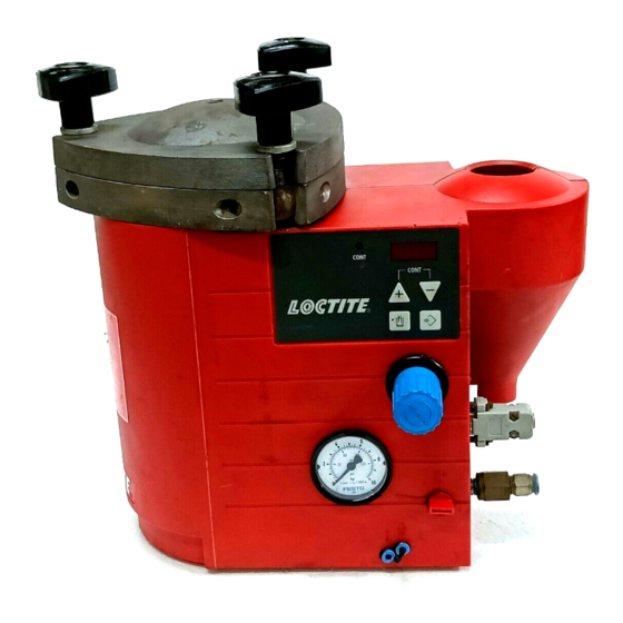
Loctite 97008 Operating Manual
2 l semi-automatic dispense system
Hide thumbs
1
2
3
Table Of Contents
4
5
6
7
8
9
10
11
12
13
14
15
16
17
18
19
20
21
22
23
24
25
26
27
28
page
of
28
Go
/
28
Contents
Table of Contents
Troubleshooting
Bookmarks
Table of Contents
Table of Contents
1 Please Observe the Following
Emphasized Sections
Items Supplied
For Your Safety
Field of Application (Intended Usage)
2 Description
Theory of Operation
Operating Elements and Connections
3 Technical Data
Electric's
Energy Requirements
Pneumatics
Connections and Dimensions
Other Data
Safety Device
Environmental and Operating Conditions
Space Requirements
Connecting the Unit
First Operation
Filling and Refilling the Product Reservoir
Adjusting the Dispensed Quantity
4 Installation
Time Controlled Mode
Continuous Mode
Shutdown for Longer Periods of Non-Use
Returning to Operation after Longer Periods of Non-Use
5 Dispensing
6 Care and Maintenance
7 Troubleshooting
Replacing the Rupture Disk
8 Special Adjustments (for Service Personal Only)
Adjusting the Level Sensor (Only 97009)
External Connection Empty Signal (Only 97009)
9 Annex
Spare Parts
Pin Assignment
Declaration of EC Conformity
Advertisement
Quick Links
1
Electric's
2
Dispensing
3
Care and Maintenance
4
Troubleshooting
5
Spare Parts
Download this manual
Operating Manual
Bedienungsanleitung
2 l Semi-Automatic Dispense System
2 l-Halbautomatisches Dosiersystem
97007/97008/97009/97010
Table of
Contents
Previous
Page
Next
Page
1
2
3
4
5
Advertisement
Table of Contents
Need help?
Do you have a question about the 97008 and is the answer not in the manual?
Ask a question
Questions and answers
Related Manuals for Loctite 97008
Dispenser Loctite LOCTITE 97504 Operating Manual
Dual rotor pump dispenser (94 pages)
Dispenser Loctite 97006 Operation Manual
Digital syringe dispenser (27 pages)
Dispenser Loctite 97006 Operating Manual
Digital syringe dispenser (44 pages)
Dispenser Loctite 97007 Operating Manual
2 l semi-automatic dispense system (28 pages)
Dispenser Loctite 97009 Operating Manual
2 l semi-automatic dispense system (28 pages)
Dispenser Loctite 983437 Operating Instructions Manual
Pneumatic dispensers for 2-component adhesives (8 pages)
Dispenser Loctite 97105 Manual
(40 pages)
Dispenser Loctite 985246 Instruction Sheet
490 ml manual applicator (2 pages)
Dispenser Loctite 98050 Instruction Sheet
Foot dispenser with vacuum (2 pages)
Dispenser Loctite 97115 Rotorspray Operating Manual
(52 pages)
Dispenser Loctite SD10 Operation Manual
Sd10 digital syringe dispenser (15 pages)
Dispenser Loctite 1390322 Operation Manual
Integrated semi-automatic dispenser dual channel with low level sensor (20 pages)
Dispenser Loctite VoluDrop UV 97650 Operating Manual
(18 pages)
Dispenser Loctite 883976 Operation Manual
Digital syringe dispenser (52 pages)
Dispenser Loctite EQ PU20 Operation Manual
Digital peristaltic dispenser (23 pages)
Dispenser Loctite PULSE EQ RC50 Operating Manual
(41 pages)
This manual is also suitable for:
97007
97010
97009
Table of Contents
Print
Rename the bookmark
Delete bookmark?
Delete from my manuals?
Login
Sign In
OR
Sign in with Facebook
Sign in with Google
Upload manual
Upload from disk
Upload from URL


Need help?
Do you have a question about the 97008 and is the answer not in the manual?
Questions and answers