Table of Contents
Advertisement
Quick Links
Advertisement
Table of Contents

Subscribe to Our Youtube Channel
Related Manuals for Advantech ARK-6320


Summary of Contents for Advantech ARK-6320
- Page 1 User Manual ARK-6320 Fanless Wallmount / Desktop Mini-ITX Embedded Computer...
- Page 2 No part of this manual may be reproduced, copied, translated or transmitted in any form or by any means without the prior written permission of Advantech Co., Ltd. Information provided in this manual is intended to be accurate and reliable. How- ever, Advantech Co., Ltd.
-
Page 3: Safety Instructions
There is a danger of explosion if battery is incorrectly replaced. Replace only with same or equivalent type recommended by the manufacture. Discard used batteries according to the manufacturer's instructions. THE COMPUTER IS PROVIDED WITH CD DRIVES COMPLY WITH APPRO- PRIATE SAFETY STANDARDS INCLUDING IEC 60825. ARK-6320 User Manual... -
Page 4: Declaration Of Conformity
Opera- tion of this equipment in a residential area is likely to cause harmful interference in which case the user will be required to correct the interference at his own expense. ARK-6320 User Manual... - Page 5 Whether your new Advantech equipment is destined for the labo- ratory or the factory floor, you can be assured that your product will provide the reliability and ease of operation for which the name Advantech has come to be known.
-
Page 6: Product Warranty
Because of Advantech’s high quality-control standards and rigorous testing, most of our customers never need to use our repair service. If an Advantech product is defec- tive, it will be repaired or replaced at no charge during the warranty period. For out- of-warranty repairs, you will be billed according to the cost of replacement materials, service time and freight. -
Page 7: Safety Precautions
Caution! There is a danger of a new battery exploding if it is incorrectly installed. Do not attempt to recharge, force open, or heat the battery. Replace the battery only with the same or equivalent type recommended by the man- ufacturer. Discard used batteries according to the manufacturer’s instructions. ARK-6320 User Manual... - Page 8 ARK-6320 User Manual viii...
-
Page 9: Table Of Contents
PS/2 Keyboard and Mouse Connector (KBMS1)......18 3.5.5 CPU Fan Connector (CPU_FAN1) ..........18 3.5.6 System FAN Connector (SYSFAN1) .......... 19 3.5.7 Front Panel Connectors (JFP1/JFP1+JFP2) ......19 Table 3.9: ATX power supply LED status (No support for AT pow- er) ................20 ARK-6320 User Manual... - Page 10 Introduction ..................... 52 Value-Added Software Services ............. 52 6.2.1 Software API................52 6.2.2 Software Utility................54 Chapter Chipset Software Installation Utility Before You Begin..................56 Introduction ..................... 56 Windows XP Driver Setup............... 57 Chapter VGA Setup ......... 59 ARK-6320 User Manual...
- Page 11 Serial ATA0/1 (SATA1/SATA2)............... 81 Table C.13:Serial ATA 0/1 (SATA1/SATA2) ....... 81 C.14 AT/ATX Mode (PSON1) ................81 Table C.14:AT/ATX Mode (PSON1) ........... 81 C.15 HD Audio Interface (HD1) ............... 81 Table C.15:AC-97 Audio Interface (HD1) ........81 ARK-6320 User Manual...
- Page 12 C.16 DMA Channel Assignments ..............82 Table C.16:DMA Channel Assignments ........82 C.17 Interrupt Assignments ................82 Table C.17:Interrupt Assignments ..........82 C.18 1st MB Memory Map................82 Table C.18:1st MB Memory Map ..........82 ARK-6320 User Manual...
-
Page 13: Chapter 1 General Information
Chapter General Information... -
Page 14: Introduction
MTBF performance. Latest low power fanless solution of Computing Platform Options The fanless ARK-6320 provides a full range of AtomTM dual core computing plat- forms for user selection: from the cutting edge ARK-6320-6M01E with AtomTM D510 processor as mainstream. -
Page 15: Specifications
Operating Non-operating Temperature 0 ~ 50°C (32 ~ 122°F) -20 ~ 60°C (-4 ~ 140°F) Humidity 10 ~ 85% @ 50°C, non-condensing 10 ~ 95% @ 50°C, non-condensing Vibration 1G rms Safety CE/FCC UL, CB, CCC compliant ARK-6320 User Manual... -
Page 16: Dimension Diagram
Dimension Diagram 200 [7.87] 73 [2.87] unit: mm [inch] Figure 1.1 Dimension diagram ARK-6320 User Manual... -
Page 17: Chapter 2 System Setup
Chapter System Setup... -
Page 18: Removing The Chassis Base
Be sure to turn off the power, unplug the power cord and ground yourself by touching the metal chassis before you handle any components inside the machine. Removing the Chassis Base Figure 2.1 Removing the chassis base ARK-6320 User Manual... -
Page 19: Figure 2.2 Removing The Front Panel
Figure 2.2 Removing the front panel Figure 2.3 Removing the rear panel Installing the SODIMM Figure 2.4 Installing the SODIMM ARK-6320 User Manual... -
Page 20: Installing Hard Disk Drives/ Cf Card
Installing Hard Disk Drives/ CF Card Figure 2.5 Installing hard disk drives Figure 2.6 Installing CF card ARK-6320 User Manual... -
Page 21: Chapter 3 Motherboard Overview
Chapter Motherboard Overview... -
Page 22: Board Layout
JFP1 & 2 5 8 11 JFP2 1 4 7 10 JWDT1 JFP1 1 2 3 4 5 PCI1 CPUFAN1 DIMM1 SYSFAN1 USB5,6 BATTERY MINIPCIE2 SATA1 SATA2 CMOS1 KBMS1 BIOS USB7,8 SATA_PWR_CN1 SATA_PWR_CN2 Figure 3.1 Motherboard layout ARK-6320 User Manual... -
Page 23: Jumpers And Connectors
HD Audio Front Panel Pin Header SATA1 Serial ATA data connector 1 SATA_PWR_CN2 Serial ATA power connector 2 DIMMA1 Memory connector channel. SPI_CN1 SPI flash update connector. MINIPCIE2 Mini PCI express connector ATX12V ATX 12 V connector ARK-6320 User Manual... -
Page 24: Motherboard Diagram
1, 2, and 3. In this case you connect either pins 1 and 2, or 2 and 3. A pair of needle-nose pliers may be useful when setting jumpers. ARK-6320 User Manual... -
Page 25: Cmos Clear (Cmos1)
Function Jumper Setting RS232 (default) (5-6) + (7-9) + (8-10) + (13-15) + (14-16) closed RS422 (3-4) + (9-11) + (10-12) + (15-17) + (16-18) closed RS-485 (1-2) + (9-11) + (10-12) + (15-17) + (16-18) closed ARK-6320 User Manual... -
Page 26: J1: Lcd Power 3.3 V/5 V Selector
AT Mode ATX Mode ATX Mode AT Mode 2-3 closed 1-2 closed 3.4.6 JWDT1: Watchdog Timer Output Option Table 3.7: JWDT1: Watchdog Timer Output Options Closed Pins Result 2-3 (default) System Reset System Reset 2-3 closed 1-2 closed ARK-6320 User Manual... -
Page 27: I/O Connections
The RJ-45 jacks on the rear panel provide for convenient LAN connection. LAN2_USB34 LAN1_USB12 LAN1_USB12 LAN2_USB34 USB56 USB78 Table 3.8: LAN LED Indicator LAN Mode Lan Indicator 1 Gbps Link on LED1 Green on 100 Mbps Link on LED1 Orange on Active LED2 Green flash ARK-6320 User Manual... -
Page 28: Vga Connector (Vga1)
VGA Connector (VGA1) This motherboard includes a VGA interface that can drive conventional CRT dis- plays. VGA1 is a standard 15-pin D-SUB connector commonly used for VGA. Pin assignments for CRT connector VGA1 are detailed in Appendix C. ARK-6320 User Manual... -
Page 29: Serial Ports (Com1~Com3)
BIOS setup. Different devices implement the RS-232/422/485 standards in different ways. If you should happen to have problems with a serial device, be sure to check the pin assignments for the connector. ARK-6320 User Manual... -
Page 30: Ps/2 Keyboard And Mouse Connector (Kbms1)
On board 6-pin wafer box connector, supports one standard PS/2 keyboard, one standard PS/2 mouse. 3.5.5 CPU Fan Connector (CPU_FAN1) If a fan is used, this connector supports cooling fans of 500 mA (6 W) or less. ARK-6320 User Manual... -
Page 31: System Fan Connector (Sysfan1)
If a fan is used, this connector supports cooling fans of 500 mA (6 W) or less. 3.5.7 Front Panel Connectors (JFP1/JFP1+JFP2) There are several external switches to monitor and control the IPC-100. JFP1 & JFP2 JFP1 ARK-6320 User Manual... -
Page 32: Table 3.9: Atx Power Supply Led Status (No Support For At Pow Er)
PSON1 Connect pins 1 & 2 to (on back plane) pins 2-3 closed pins 1-2 closed panel switch via cable jumper setting System On System Suspend Fast flashes Fast flashes Fast flashes System Off Slow flashes ARK-6320 User Manual... -
Page 33: Line Out, Mic In Connector (Audio1)
Line Out, Mic In Connector (AUDIO1) Line Out Mic In 3.5.9 Serial ATA Interface (SATA1, SATA2) It features a high performance Serial ATA interface (up to 300 MB/s) which eases cabling to hard drives with long, thin cables. ARK-6320 User Manual... -
Page 34: Front Headphone Connector (Hd1)
I/O module cable. Note! For motherboards with the optional HD Audio feature, we recommend that you connect a high-definition front panel audio module to this con- nector to take advantage of the motherboard’s high definition audio capability. ARK-6320 User Manual... -
Page 35: Atx 12V Power Connector (Atx12V)
Determine the proper orientation and push down firmly until the connectors mate completely. 3.5.12 SPI Flash connector(SPI_CN1) The SPI flash card pin header may be used to flash BIOS if the motherboard cannot power on. ARK-6320 User Manual... - Page 36 ARK-6320 User Manual...
-
Page 37: Operation
Chapter Operation... -
Page 38: The System Front Panel
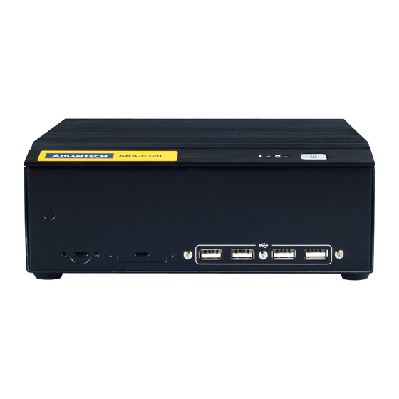
Table 4.1: Definition of LED indicators Icon Description Blue No light Power Power Normal Off or failure Hard Disk Reading NO reading Temp Over-heating Normal Over (Red) Note! The temperature indicator LED is accurate to within ±5°C. ARK-6320 User Manual... -
Page 39: Io Placement
Front Panel Power switch 4 USB Antenna Reserve IO for LVDS and inverter Rear Panel Dual Giga LANs 4 USB Audio 6 COMs Antenna DC12 V input (drum type) Figure 4.1 Front panel Figure 4.2 Rear panel ARK-6320 User Manual... - Page 40 ARK-6320 User Manual...
-
Page 41: Bios Operation
Chapter BIOS Operation... -
Page 42: Introduction
Increase the numeric value or make changes <Page Down/-> Decrease the numeric value or make changes <F1> General help, for Setup Sub Menu <F2> Item Help <F5> Load Previous Values <F7> Load Setup Defaults <F10> Save all CMOS changes ARK-6320 User Manual... -
Page 43: Main Menu
System Date using the <Arrow> keys. Enter new values through the keyboard. Press the <Tab> key or the <Arrow> keys to move between fields. The date must be entered in MM/DD/YY format. The time must be entered in HH:MM:SS format. ARK-6320 User Manual... -
Page 44: Advanced Bios Features
BIOS Setup option by highlighting it using the <Arrow> keys. All Advanced BIOS Setup options are described in this section. The Advanced BIOS Setup screen is shown below. The sub menus are described on the following pages. ARK-6320 User Manual... -
Page 45: Cpu Configuration
CPU speed is controlled by the operating system. Intel® C-STATE tech This item allows the CPU to save more power under idle mode. Enhanced C-States CPU idle set to enhanced C-States, disabled by Intel®. C-STATE tech item. ARK-6320 User Manual... -
Page 46: Ide Configuration
While entering setup, BIOS auto detects the pres- ence of AHCI devices. This displays the status of auto detection of AHCI devices. Super I/O Configuration This item enables users to set the Super IO device status, including enabling of COMs. ARK-6320 User Manual... - Page 47 This item allows user to adjust serial port 4 address and IRQ. Onboard Serial port 5 [C90/IRQ11] This item allows user to adjust serial port 5 address and IRQ. Onboard Serial port 6 [C98/IRQ10] This item allows user to adjust serial port 6 address and IRQ. ARK-6320 User Manual...
-
Page 48: Hardware Health Configuration
Use this to set the CPU warning temperature threshold. When the system CPU reaches the warning temperature, the buzzer will sound. ACPI Shut Down Temperature This allows the user to set the CPU temperature at which the system will auto- matically shut down to prevent CPU overheat damage. ARK-6320 User Manual... -
Page 49: Acpi Setting
5.2.6 ACPI Setting 5.2.7 General ACPI Configuration Suspend mode Select the ACPI state used for system suspend. Report Video on S3 Resume This item allows you to invoke VA BIOS POST on S3/STR resume. ARK-6320 User Manual... -
Page 50: Advanced Acpi Configuration
This item allows you to enable RSDP pointers to 64-bit fixed system description tables. ACPI APIC support Include APIC table pointer to RSDT pointer list. AMI OEMB table Include OEMB table pointer to R(x)SDT pointer lists. Headless mode Enable / Disable Headless operation mode through ACPI. ARK-6320 User Manual... -
Page 51: Chipset Acpi Configuration
Allows you to configure Intel’s Energy Lake power management technology. APIC ACPI SCI IRQ Enable/Disable APIC ACPI SCI IRQ. USB Device Wakeup From S3/S4 Enable/Disable USB Device Wakeup from S3/S4. High Performance Event Timer Enable/Disable High performance Event timer. ARK-6320 User Manual... -
Page 52: Apm Configuration
This option allows user to set system action when AC power restores after AC power loss. Available options include Power Off, Power On, Last Status. Resume On Ring Disable/Enable RI wake event. Resume On RTC Alarm Disable/Enable RTC wake event. ARK-6320 User Manual... -
Page 53: Usb Configuration
EHCI driver. Hotplug USB FDD Support A dummy FDD device is created that will be associated with the hotplugged FDD later. Auto option creates this dummy device only if there is no USB FDD present. ARK-6320 User Manual... -
Page 54: Usb Mass Storage Device Configuration
You can display a Plug and Play BIOS Setup option by highlighting it using the <Arrow> keys. All Plug and Play BIOS Setup options are described in this sec- tion. The Plug and Play BIOS Setup screen is shown below. ARK-6320 User Manual... -
Page 55: Boot Settings
When set to Reserved, will specified DMA is Reserved for use by leg- acy ISA devices. Reserved Memory Size This item allows you to reserve a set amount of memory for legacy ISA devices. 5.2.14 Boot Settings ARK-6320 User Manual... -
Page 56: Boot Settings Configuration
Wait for the F1 key to be pressed if an error occurs. Hit .DEL. Message Display Displays .Press DEL to run Setup. in POST. Interrupt 19 Capture This item allows option ROMs to trap interrupt 19. Bootsafe Function This item allows you to enable or disable bootsafe function. ARK-6320 User Manual... -
Page 57: Security Setup
Change Supervisor / User Password Provides for either installing or changing the password. Boot sector Virus protection The boot sector virus protection will warn if any program tries to write to the boot sector. 5.2.17 Advanced Chipset Settings ARK-6320 User Manual... -
Page 58: North Bridge Chipset Configuration
This item allows you to enable or disable detect by DRAM SPD. Initiate Graphic Adapter This item allows you to select which graphics controller to use as the primary boot device. Internal Graphics Mode Select Select the amount of system memory used by the Internal graphics device. ARK-6320 User Manual... -
Page 59: Video Function Configuration
Boot Display Device Select boot display device at post stage. Flat Panel Type This item allows you to select which panel resolution you want. Spread Spectrum Clock This item allows you to enable or disable spread spectrum clock. ARK-6320 User Manual... -
Page 60: South Bridge Chipset Configuration
Enables or disables GbE LAN wake up from S5 function. HDA Controller Enables or disables the HDA controller. SMBUS Controller Enables or disables the SMBUS controller. SLP_S4# Min. Assertion Width This item allows you to set a delay of a set number of seconds. ARK-6320 User Manual... -
Page 61: Exit Option
Select this option to quit Setup without making any permanent changes to the system configuration. Select Discard Changes and Exit from the Exit menu and press <Enter>. The following message appears: Discard Changes and Exit Setup Now? [Ok] [Cancel] Select Ok to discard changes and exit. Discard Changes ARK-6320 User Manual... - Page 62 Select Failsafe Defaults if your computer is experiencing system configuration problems. Select Load Failsafe Defaults from the Exit menu and press <Enter>. The fol- lowing message appears: Load Failsafe Defaults? [OK] [Cancel] Select OK to load Failsafe defaults. ARK-6320 User Manual...
-
Page 63: Software Introduction & Service
Chapter Software Introduction & Service... -
Page 64: Introduction
Introduction The mission of Advantech Embedded Software Services is to "Enhance quality of life with Advantech platforms and Microsoft® Windows® embedded technology." We enable Windows® Embedded software products on Advantech platforms to more effectively support the embedded computing community. Customers are freed from the hassle of dealing with multiple vendors (hardware suppliers, system integrators, embedded OS distributors) for projects. - Page 65 System Throttling Refers to a series of methods for reducing power consump- tion in computers by lowering the clock frequency. This API allows the user to adjust the clock from 87.5% to 12.5%. ARK-6320 User Manual...
-
Page 66: Software Utility
The eSOS also provide for remote connection via Telnet server and FTP server so the administrator can attempt to rescue the system. Note: This function requires BIOS cus- tomization. ARK-6320 User Manual... -
Page 67: Chipset Software Installation Utility
Chapter Chipset Software Installation Utility... -
Page 68: Before You Begin
DVD content, and MPEG-2 motion compensation for software DVD Note! This utility is used for the following versions of Windows, and it has to be installed before installing all the other drivers: Windows 7 Windows Vista Windows XP ARK-6320 User Manual... -
Page 69: Windows Xp Driver Setup
Windows XP Driver Setup Insert the driver CD into your system's CD-ROM drive. You can see the driver folder items. Navigate to the "Chipset" folder and click "infinst_autol.exe" to complete the installation of the driver. ARK-6320 User Manual... - Page 70 ARK-6320 User Manual...
-
Page 71: Vga Setup
Chapter VGA Setup... -
Page 72: Introduction
Insert the driver CD into your system's CD-ROM drive. You can see the driver folders items. Navigate to the "VGA" folder and click "setup.exe" to complete the installation of the drivers for Windows 7, Windows Vista, Windows XP. ARK-6320 User Manual... -
Page 73: Chapter 9 Lan Configuration
Chapter LAN Configuration... -
Page 74: Introduction
The Intel 82567V (LAN1) and 82583V (LAN2) Gigabit integrated controllers support all major network operating systems. However, the installation procedure varies from system to system. Please find and use the section that provides the driver setup pro- cedure for the operating system you are using. ARK-6320 User Manual... -
Page 75: Windows 7/Vista/Xp Driver Setup (Intel 82567V/82583V)
Windows 7/Vista/XP Driver Setup (Intel 82567v/ 82583v) Insert the driver CD into the slim ODD. Select the LAN folder then navigate to the directory for your OS. ARK-6320 User Manual... - Page 76 ARK-6320 User Manual...
-
Page 77: Appendix A Exploded Diagram
Appendix Exploded Diagram... -
Page 78: Exploded Diagram
Exploded Diagram Figure A.1 Exploded diagram ARK-6320 User Manual... - Page 79 Appendix Programming the Watchdog Timer...
-
Page 80: Appendix B Programming The Watchdog Timer
2F (hex) is the data port. You must first assign the address of register by writing an address value into address port 2E (hex), then write/read data to/from the assigned register through data port 2F (hex). ARK-6320 User Manual... - Page 81 Unlock W83627DHG-P Select register of watchdog timer Enable the function of the watchdog timer Use the function of the watchdog timer Lock W83627DHG-P ARK-6320 User Manual...
-
Page 82: Table B.1: Watchdog Timer Registers
Bit 5: Write 1 to generate a timeout signal immedi- ately and automatically return to 0. [default=0] Bit 4: Read status of watchdog timer, 1 means timer is “timeout”. Write this address to I/O port 2E (hex) to lock the AA (hex) ----- watchdog timer 2. ARK-6320 User Manual... -
Page 83: Example Program
Inc dx Mov al,10 Out dx,al ;----------------------------------------------------------- Dec dx ; Lock W83627DHG-P Mov al,0aah Out dx,al Enable watchdog timer and set 5 minutes as timeout interval ;----------------------------------------------------------- Mov dx,2eh ; Unlock W83627DHG-P Mov al,87h Out dx,al Out dx,al ARK-6320 User Manual... - Page 84 Enable watchdog timer to be reset by mouse ;----------------------------------------------------------- Mov dx,2eh ; Unlock W83627DHG-P Mov al,87h Out dx,al Out dx,al ;----------------------------------------------------------- Mov al,07h ; Select registers of watchdog timer Out dx,al Inc dx Mov al,08h Out dx,al ;----------------------------------------------------------- ARK-6320 User Manual...
- Page 85 Dec dx ; Enable the function of watchdog timer Mov al,30h Out dx,al Inc dx Mov al,01h Out dx,al ;----------------------------------------------------------- Dec dx ; Enable watchdog timer to be strobed reset by keyboard Mov al,0f7h Out dx,al Inc dx In al,dx Or al,40h Out dx,al ARK-6320 User Manual...
- Page 86 Dec dx ; Generate a time-out signal Mov al,0f7h Out dx,al ;Write 1 to bit 5 of F7 register Inc dx In al,dx Or al,20h Out dx,al ;----------------------------------------------------------- Dec dx ; Lock W83627DHG-P Mov al,0aah Out dx,al ARK-6320 User Manual...
-
Page 87: Appendix C I/O Pin Assignments
Appendix I/O Pin Assignments... -
Page 88: Usb Header (Usb56, Usb78)
USB Header (USB56, USB78) Table C.1: USB Header (USB56) Signal Signal USB0_VCC5 USB1_VCC5 USB0_D- USB1_D- USB0_D+ USB1_D+ VGA Connector (VGA1) Table C.2: VGA Connector (VGA1) Signal Signal CRT_VCCIN VGA_G VGA_B V_SDAT H-SYNC V-SYNC V_SCLK ARK-6320 User Manual... -
Page 89: Rs-232 Interface
Table C.3: RS-232 Interface (COM4~COM6) Signal Signal RS-232/422/485 Setting Interface (JETCOM2) Table C.4: RS-232/422/485 Setting Interface (JETCOM2) Signal Signal R_SINA RXD485_1 R_SINA RXD422_1 R_SINA RXD232_1 DCDA SOUTA COM1_DCD# COM1_SOUT COM1_TXD485N COM1_RXD485P SINA DTRA COM1_SIN COM1_DTR# COM1_TXD485P COM1_RXD485N ARK-6320 User Manual... -
Page 90: Spi_Cn1: Spi Fresh Card Pin Connector
F1_SPI_MOSI_Q PS/2 Keyboard and Mouse Connector (KBMS1) Table C.6: PS/2 Keyboard and Mouse Connector (KBMS1) Signal KCLK_B KDAT_B MDAT_B KBMS1_VCC MCLK_B CPU Fan Power Connector (CPU_FAN1) Table C.7: CPU Fan Power Connector (CPU_FAN1) Signal +12 V DETECT ARK-6320 User Manual... -
Page 91: System Fan Power Connector (Cha_Fan1)
You can use an LED to indicate when the single board computer is on. Pin 1 of JFP3 supplies the LED's power, and Pin 3 is the ground. Table C.9: Power LED & Keyboard Lock Connector (JFP1) Function LED power KEYLOCK# ARK-6320 User Manual... -
Page 92: Power Switch/Hdd Led/Smbus/Speaker (Jfp1+Jfp2)
Table C.10: Power Switch/HDD LED/SMBus/Speaker (JFP1+JFP2) Signal Signal SPK_P1 HDDLED+ HDDLED- SPK_P3 SMB_DAT SYS_RST SPK_P4 SMB_CLK C.11 USB/LAN ports (LAN1_USB12/LAN2_USB34) Table C.11: USB Port Signal Signal Data0+ Data0- Table C.12: Ethernet 10/100 Mbps RJ-45 Port Signal Signal XMT+ XMT- RCV- RCV+ ARK-6320 User Manual... -
Page 93: Line Out, Mic In Connector (Audio1)
AT/ATX Mode (PSON1) Table C.14: AT/ATX Mode (PSON1) Signal Signal #PSON_SIO #PSON (to super IO) (to power supply) C.15 HD Audio Interface (HD1) Table C.15: AC-97 Audio Interface (HD1) Signal Signal MIC2_L MIC2_R FP_AUD_DET LOUT2_R SRTN1 LOUT2_DET LOUT2_L SRTN2 ARK-6320 User Manual... -
Page 94: Dma Channel Assignments
1st MB Memory Map Table C.18: 1st MB Memory Map Addr. range (Hex) Device E0000h - FFFFFh BIOS CC000h - DFFFFh Unused C0000h - CBFFFh VGA BIOS A0000h - BFFFFh Video Memory 00000h - 9FFFFh Base memory ARK-6320 User Manual... - Page 95 ARK-6320 User Manual...
- Page 96 No part of this publication may be reproduced in any form or by any means, electronic, photocopying, recording or otherwise, without prior written permis- sion of the publisher. All brand and product names are trademarks or registered trademarks of their respective companies. © Advantech Co., Ltd. 2010...
Need help?
Do you have a question about the ARK-6320 and is the answer not in the manual?
Questions and answers