Sign In
Upload
Manuals
Brands
Advantech Manuals
Desktop
ARK-6320
Advantech ARK-6320 Manuals
Manuals and User Guides for Advantech ARK-6320. We have
1
Advantech ARK-6320 manual available for free PDF download: User Manual
Advantech ARK-6320 User Manual (96 pages)
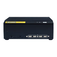
Fanless Wallmount / Desktop Mini-ITX Embedded Computer
Brand:
Advantech
| Category:
Desktop
| Size: 6.87 MB
Table of Contents
Safety Instructions
3
Declaration of Conformity
4
Product Warranty
6
Safety Precautions
7
Table of Contents
9
Chapter 1 General Information
13
Introduction
14
Specifications
15
Environmental Specifications
15
Table 1.1: Environment Specifications
15
Dimension Diagram
16
Figure 1.1 Dimension Diagram
16
Chapter 2 System Setup
17
Removing the Chassis Base
18
Figure 2.1 Removing the Chassis Base
18
Figure 2.2 Removing the Front Panel
19
Figure 2.3 Removing the Rear Panel
19
Installing the SODIMM
19
Figure 2.4 Installing the SODIMM
19
Installing Hard Disk Drives/ CF Card
20
Figure 2.5 Installing Hard Disk Drives
20
Figure 2.6 Installing CF Card
20
Chapter 3 Motherboard Overview
21
Board Layout
22
Figure 3.1 Motherboard Layout
22
Jumpers and Connectors
23
Table 3.1: Jumpers
23
Table 3.2: Connectors
23
Motherboard Diagram
24
Figure 3.2 Motherboard Diagram
24
Jumper Settings
24
How to Set Jumpers
24
CMOS Clear (CMOS1)
25
Table 3.3: CMOS1
25
COM2 RS 232/422/485 Mode Selector (JSETCOM2)
25
Table 3.4: COM2 RS 232/422/485 Mode Selector (JSETCOM2
25
J1: LCD Power 3.3 V/5 V Selector
26
Table 3.5: J1: LCD Power 3.3 V/5 V Selector
26
PSON1: ATX, at Mode Selector
26
Table 3.6: PSON1: ATX, at Mode Selector
26
JWDT1: Watchdog Timer Output Option
26
Table 3.7: JWDT1: Watchdog Timer Output Options
26
I/O Connections
27
USB Ports (LAN1_USB12/LAN2_USB34/USB56/USB78)
27
Table 3.8: LAN LED Indicator
27
VGA Connector (VGA1)
28
Serial Ports (COM1~COM3)
29
PS/2 Keyboard and Mouse Connector (KBMS1)
30
CPU Fan Connector (CPU_FAN1)
30
System FAN Connector (SYSFAN1)
31
Front Panel Connectors (JFP1/JFP1+JFP2)
31
Table 3.9: ATX Power Supply LED Status (no Support for at Pow Er)
32
Line Out, MIC in Connector (AUDIO1)
33
Serial ATA Interface (SATA1, SATA2)
33
Front Headphone Connector (HD1)
34
ATX 12V Power Connector (ATX12V)
35
SPI Flash Connector(SPI_CN1)
35
Operation
37
Chapter 4 Operation
37
The System Front Panel
38
Power Button
38
LED Indicators for System Status
38
Table 4.1: Definition of LED Indicators
38
IO Placement
39
Figure 4.1 Front Panel
39
Figure 4.2 Rear Panel
39
BIOS Operation
41
Chapter 5 BIOS Operation
41
Introduction
42
BIOS Setup
42
Main Menu
43
Advanced BIOS Features
44
CPU Configuration
45
IDE Configuration
46
Hardware Health Configuration
48
ACPI Setting
49
General ACPI Configuration
49
Advanced ACPI Configuration
50
Chipset ACPI Configuration
51
APM Configuration
52
USB Configuration
53
USB Mass Storage Device Configuration
54
Advanced Pci/Pnp Settings
54
Boot Settings
55
Boot Settings Configuration
56
Security Setup
57
Advanced Chipset Settings
57
North Bridge Chipset Configuration
58
Video Function Configuration
59
South Bridge Chipset Configuration
60
Exit Option
61
Chapter 6 Software Introduction & Service
63
Introduction
64
Value-Added Software Services
64
Software API
64
Software Utility
66
Chapter 7 Chipset Software Installation Utility
67
Before You Begin
68
Introduction
68
Windows XP Driver Setup
69
VGA Setup
71
Chapter 8 VGA Setup
71
Introduction
72
Windows 7/Vista/Xp
72
Chapter 9 LAN Configuration
73
Introduction
74
Features
74
Installation
74
Windows 7/Vista/Xp Driver Setup (Intel 82567V/82583V)
75
Appendix A Exploded Diagram
77
Exploded Diagram
78
Figure A.1 Exploded Diagram
78
Appendix B Programming the Watchdog Timer
80
Programming the Watchdog Timer
80
Watchdog Timer Overview
80
Table B.1: Watchdog Timer Registers
82
Example Program
83
B.1.3 Example Program
83
Appendix C I/O Pin Assignments
87
USB Header (USB56, USB78)
88
VGA Connector (VGA1)
88
Table C.1: USB Header (USB56)
88
Table C.2: VGA Connector (VGA1)
88
RS-232 Interface
89
Table C.3: RS-232 Interface (COM4~COM6)
89
RS-232/422/485 Setting Interface (JETCOM2)
89
Table C.4: RS-232/422/485 Setting Interface (JETCOM2)
89
SPI_CN1: SPI Fresh Card Pin Connector
90
Table C.5: SPI_CN1:SPI Fresh Card Pin Connector
90
PS/2 Keyboard and Mouse Connector (KBMS1)
90
Table C.6: PS/2 Keyboard and Mouse Connector (KBMS1)
90
CPU Fan Power Connector (CPU_FAN1)
90
Table C.7: CPU Fan Power Connector (CPU_FAN1)
90
System Fan Power Connector (CHA_FAN1)
91
Power LED & Keyboard Lock Connector (JFP1)
91
Table C.9: Power LED & Keyboard Lock Connector (JFP1)
91
Power Switch/Hdd Led/Smbus/Speaker (JFP1+JFP2)
92
(Jfp1+Jfp2)
92
USB/LAN Ports (LAN1_USB12/LAN2_USB34)
92
Table C.11:USB Port
92
Table C.12:Ethernet 10/100 Mbps RJ-45 Port
92
Line Out, MIC in Connector (AUDIO1)
93
Serial ATA0/1 (SATA1/SATA2)
93
Table C.13:Serial ATA 0/1 (SATA1/SATA2)
93
AT/ATX Mode (PSON1)
93
Table C.14:AT/ATX Mode (PSON1)
93
HD Audio Interface (HD1)
93
Table C.15:AC-97 Audio Interface (HD1)
93
DMA Channel Assignments
94
Table C.16:DMA Channel Assignments
94
Interrupt Assignments
94
Table C.17:Interrupt Assignments
94
St MB Memory Map
94
Table C.18:1St MB Memory Map
94
Advertisement
Advertisement
Related Products
Advantech ARK-6310
Advantech ARK-3381 Series
Advantech ARK-3520P-U8A1E
Advantech ARK-3382-1S1A1
Advantech ARK-3380-1S4A1
Advantech ARK-3382-1S4B1E
Advantech ARK-2232
Advantech ARK-4170
Advantech ARK-2121L-U0A1E
Advantech ARK-1221L
Advantech Categories
Motherboard
Computer Hardware
Desktop
Touch Panel
Network Router
More Advantech Manuals
Login
Sign In
OR
Sign in with Facebook
Sign in with Google
Upload manual
Upload from disk
Upload from URL