
Related Manuals for Advantech ARK-6310


Summary of Contents for Advantech ARK-6310
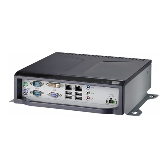
- Page 1 User Manual ARK-6310 Fanless Wallmount / Desktop Mini-ITX Embedded Computer with Front I/O Interface...
- Page 2 No part of this manual may be reproduced, copied, translated or transmitted in any form or by any means without the prior written permission of Advantech Co., Ltd. Information provided in this manual is intended to be accurate and reliable. How- ever, Advantech Co., Ltd.
- Page 3 Because of Advantech’s high quality-control standards and rigorous testing, most of our customers never need to use our repair service. If an Advantech product is defec- tive, it will be repaired or replaced at no charge during the warranty period. For out- of-warranty repairs, you will be billed according to the cost of replacement materials, service time and freight.
- Page 4 ARK-6310 Packing and Model List ARK-6310 Series Model There are three sub-models in ARK-6310 series as listed below: Part Number Description ARK-6310-3M01E LV Pentium M 1.4GHz Mini-ITX wallmount Embedded Box Computer, with VGA, 1 x Gigabit Ethernet, AC97 Audio 1 x RS-232/422/485, 1 x LPT, 2 x USB, 2 x PS/2 (KB &...
-
Page 5: Declaration Of Conformity
Technical Support and Assistance Visit the Advantech website at www.advantech.com/support where you can find the latest information about the product. Contact your distributor, sales representative, or Advantech's customer service center for technical support if you need additional assistance. -
Page 6: Warnings And Cautions
Caution! Cautions are included to help you avoid damaging hardware or losing data. Document Feedback To assist us in making improvements to this manual, we welcome comments and constructive criticism. Please send all such - in writing - to: support@advantech.com ARK-6310 User Manual... -
Page 7: Safety Instructions
The sound pressure level at the operator's position according to IEC 704-1:1982 is no more than 70 dB (A). DISCLAIMER: This set of instructions is given according to IEC 704-1. Advantech disclaims all responsibility for the accuracy of any statements contained herein. - Page 8 Only then remove circuit boards from their antistatic bags. Handle boards by the edges or mounting brackets only; do not touch components or connecting pins. ARK-6310 User Manual viii...
-
Page 9: Table Of Contents
Contents Chapter General Information ......1 Introduction ....................2 General Features of ARK-6310..............2 Table 1.1: General Features of ARK-6310 ........2 Specifications of Three ARK-6310 Models ..........3 1.3.1 ARK-6310-3M01E................. 3 Table 1.2: Specifications of ARK-6310-3M01E ......3 1.3.2 ARK-6310-3M02E................. 4 Table 1.3: Specifications of ARK-6310-3M02E ...... - Page 10 2.7.7 Serial SATA Connector (SATA1 ~ 3 on ARK-6310-6M01E) ..23 2.7.8 Serial Port Connectors (JCOM1/2 on ARK-6310-3M01E/02E; COM3/4 on ARK-6310-6M01E) ..........23 Table 2.7: Serial port connector pin assignments ..... 23 2.7.9 Front Panel Connector (JFP1 on ARK-6310-3M01E/02E; FPIO1 on ARK-6310-6M01E) ..............
- Page 11 VESA Mounting Bracket ....81 Dimension of VESA Mounting Bracket............ 82 Figure C.1 Dimension of VESA Mounting Bracket ..... 82 Installing the VESA Mounting Bracket to ARK-6310....... 83 Figure C.2 Installing the VESA Mounting Bracket to ARK-6310 83 ARK-6310 User Manual...
- Page 12 ARK-6310 User Manual...
-
Page 13: Chapter 1 General Information
Chapter General Information... -
Page 14: Introduction
ARK-6310-3M01E with Pentium® M processor, down to the entry- level ARK-6310-3M02E with the most cost-effective Celeron® processor. Other com- puting platforms will be released in time and will share most of the ARK-6310 mechanical components. This modularized design concept will allow ARK-6310- based systems to be upgraded without modifying or changing supporting equipment. -
Page 15: Specifications Of Three Ark-6310 Models
Table 1.1: General Features of ARK-6310 Operating Temp. 0 ~ 40°C (32 ~ 104°F) Non-operating Temp. -20 ~ 60°C (-4 ~ 140°F) Operating Humidity 10 ~ 85% @ 40°C, non-condensing Environment Non-operating Humidity 10 ~ 95% @ 40°C, non-condensing Operating Vibration... -
Page 16: Ark-6310-3M02E
1.3.2 ARK-6310-3M02E Table 1.3: Specifications of ARK-6310-3M02E Intel® ULV Celeron® 600 MHz Front Side Bus 400 MHz Computing System L2 Cache 512 KB Chipset Intel® 852GM + ICH4 BIOS Award 4 Mbit FWH Technology DDR 200/266 SDRAM (ECC/Non-ECC support) Memory Max. -
Page 17: Ark-6310-6M01E
1.3.3 ARK-6310-6M01E Table 1.4: Specifications of ARK-6310-6M01E Intel® Core™ 2 Duo 1.06 GHz (U7500) Front Side Bus 533 MHz Computing System L2 Cache 2 MB Chipset Intel® GME965 + ICH8M BIOS Award 16 Mbit SPI Technology DDR2 533/667 SDRAM Memory Max. -
Page 18: Ark-6310 Dimensions
ARK-6310 Dimensions Figure 1.1 ARK-6310 Dimensions ARK-6310 User Manual... -
Page 19: Chapter 2 System Setup And Maintenance
Chapter System Setup and Maintenance... -
Page 20: Connecting The Power
Connecting the Power The ARK-6310 Embedded Systems have built in a power inlet by a 2-pole of Phoenix connector, that could allow users to connect 14 V ~24 V input voltage externally. -
Page 21: Installing/Changing The Motherboard And Heatsink Set
Installing/Changing the Motherboard and Heatsink Set With high performance and easy maintenance fanless heatsink, each ARK- 6310 compact embedded computer is equipped with an Advantech Mini-ITX motherboard. Please refer to the following steps to install or replace a motherboard and heatsink set. -
Page 22: Figure 2.4 Installing Heatsink Set
Before installing the heatsink, be sure to remove the protective film on the thermal pad first Thermal Heatsink Set: remove the protective film on the thermal pad, then carefully attach to the processor and North Bridge chip M3 screw x 4 pieces Figure 2.4 Installing Heatsink Set ARK-6310 User Manual... -
Page 23: Computing Core Overview
Please refer to Section 2.6 for detailed connector placement illustration. Parallel Line_In COM1 Line_Out Mic_In PS/2 KB JCOM2 JCOM1 (Reserved) PS/2 Mouse (Reserved) USB0,1 MPCI1 JFP1 DIMM1 POWER1 JBAT1 JLVDS1 JTMDS1 IDE1 IDE2 JTV1 (Reserved) (Reserved) (Reserved) (Rear side) Figure 2.5 ARK-6310-3M01E/02E Board Placement ARK-6130 User Manual... -
Page 24: Ark-6310-6M01E Board Placement
AUDIO1 USB2 USB1 JCOMPWR2 JCOMPWR4 (Reserved) JCOMPWR3 FPIO1 (Reserved) COM4 (Reserved) COM3 (Reserved) SO-DIMM1 ATXPWR1 SO-DIMM2 CCMOS1 SATA3 (Reserved) USB3 (Reserved) USB4 IDE1 SATA1 JLVDS1 (Reserved) (Reserved) (Reserved) (Rear side) SATA2 (Reserved) Figure 2.6 ARK-6310-6M01E Board Placement ARK-6310 User Manual... -
Page 25: Installing/Changing The Dram
Installing/Changing the DRAM ARK-6310-3M01E/02E provides one 184-pin DIMM socket to support DDR SDRAM. The total maximum memory size is 1GB. Figure 2.7 ARK-6310-3M01E/02E DIMM Socket Location ARK-6130 User Manual... -
Page 26: Figure 2.8 Ark-6310-6M01E Sodimm Sockets Location
ARK-6310-6M01E provides two 200-pin SODIMM sockets to support DDR2 SDRAM. The total maximum memory size is 4 GB. Figure 2.8 ARK-6310-6M01E SODIMM Sockets Location Warning! Make sure to unplug the power supply before adding or removing DIMMs or other system components. Failure to do so may cause severe damage to both the board and the components. -
Page 27: Jumper And Connector List
If you have any doubts about the best hard- ware configuration for your application, contact your local distributor or sales representative before you make any changes. 2.6.1 ARK-6310 Jumper List The following tables list the function of each of the system's jumpers and connectors. Jumpers Table 2.2: Jumpers... -
Page 28: Ark-6310 Front Panel Connectors
Both ARK-6310-3M01/02E and ARK-6310-6M01E have reserved extra pre-punched cutouts listed below. Customers may use them for the ded- icated internal connectors on the enclosed motherboard. ARK-6310-3M01E/02E: 2 x COM, 1 x DVI/LVDS, 1 x S/C-Video ARK-6310-6M01E: 1 x COM, 4 x USB (Optional) ARK-6310 User Manual... -
Page 29: Ark-6310 Internal Connector List
USB 3 ~ 5 USB connectors MPCI1 Mini PCI slot SATA 1 ~ 3 Serial ATA connectors SO-DIMM1/2 200-pin SODIMM sockets Note! Please refer to page 13 (for ARK-6310-3M01E/02E) and page 14 (for ARK-6310-6M01E), to find out each jumper/connector location. ARK-6130 User Manual... -
Page 30: Setting Jumpers & Connectors
Caution! Except when clearing the CMOS, never remove the cap on JBAT1 jumper default position. Removing the cap will cause system boot fail- ure! Normal (Default) Clear CMOS 2.7.2 COM +RI/+5V/+12V Selection (JP1 on ARK-6310-3M01E/02E; JCOMPWR1 ~ 4 on ARK-6310-6M01E) Ring (Default) +5 V +12 V ARK-6310 User Manual... -
Page 31: Com1 Rs-232/422/485 Select (Jp2, Jp3 On Ark-6310-3M01E/ 02E)
2.7.3 COM1 RS-232/422/485 Select (JP2, JP3 on ARK-6310-3M01E/ 02E) (JP2) (JP3) ARK-6130 User Manual... -
Page 32: Atx Power Connector (Atxpwr1)
2.7.4 ATX Power Connector (ATXPWR1) Table 2.4: ATX Power Connector (ATXPWR1) Signal Signal +12V VCCSB PWROK PS_ON +3.3V -12V +3.3V +3.3V ARK-6310 User Manual... -
Page 33: Primary Ide Connector (Ide_1)
2.7.5 Primary IDE Connector (IDE_1) Table 2.5: Primary IDE Connector (IDE_1) Signal Signal RESET# PDD7 PDD8 PDD6 PDD9 PDD5 PDD10 PDD4 PDD11 PDD3 PDD12 PDD2 PDD13 PDD1 PDD14 PDD0 PDD15 PDREQ PDIOW# PDIOR# PIORDY PDDACK# IRQ14 PDA1 PATADET PDA0 PDA2 PDCS1# PDCS3# IDEACTP#... -
Page 34: Secondary Ide Connector (Ide_2 On Ark-6310-3M01E/02E)
2.7.6 Secondary IDE Connector (IDE_2 on ARK-6310-3M01E/02E) Table 2.6: Secondary IDE Connector (IDE_2 on ARK-6310-3M01E/02E) Signal Signal RESET# SDD7 SDD8 SDD6 SDD9 SDD5 SDD10 SDD4 SDD11 SDD3 SDD12 SDD2 SDD13 SDD1 SDD14 SDD0 SDD15 SDREQ SDIOW# SDIOR# SIORDY SDDACK# IRQ15... -
Page 35: Serial Sata Connector (Sata1 ~ 3 On Ark-6310-6M01E)
2.7.7 Serial SATA Connector (SATA1 ~ 3 on ARK-6310-6M01E) The System board of ARK-6310-6M01E has 3 SATA connectors: SATA 1 (rec- ommend to use as default), SATA 2 (reserved) and SATA 3 (reserved). SATA 2 and SATA 3 are designed and reserved for future new product developments. -
Page 36: Ark-6310-6M01E
2.7.9 Front Panel Connector (JFP1 on ARK-6310-3M01E/02E; FPIO1 on ARK-6310-6M01E) ARK-6310-3M01/02E ARK-6310-6M01E Table 2.8: Front Panel Connector (JFP1 on ARK-6310-3M01E/02E) Signal Signal RESET SYS_LED+ SYS_LED- HDD_LED+ PWR_LED+ HDD_LED- PWR_LED- VCCSB SUS_LED+ PWR_BUT SUS_LED- SUS_BUT SPK+ SPK- Table 2.9: Front Panel Connector (FPIO1 on ARK-6310-6M01E) -
Page 37: Lvds Connector (Jlvds1 On Ark-6310-3M01E/02E)
2.7.10 LVDS Connector (JLVDS1 on ARK-6310-3M01E/02E) Table 2.11: LVDS Connector (JLVDS1 on ARK-6310-3M01E/02E) Signal Signal +3.3V +3.3V I2C_DAT I2C_CLK Txout0 Txout1 Txout0# Txout1# Txout2 Txout3 Txout2# Txout3# E_Txout0 E_Txout1 E_Txout0# E_Txout1# E_Txout2 E_Txout3 E_Txout2# E_Txout3# Txclk E_Txclk Txclk# E_Txclk# +12V... -
Page 38: Tmds Dvi Connector (Jtmds1 On Ark-6310-3M01E/02E)
2.7.11 TMDS DVI Connector (JTMDS1 on ARK-6310-3M01E/02E) Table 2.13: TMDS DVI Connector (JTMDS1 on ARK-6310-3M01E/02E) Signal Signal TDC0# TDC0 HPDET TDC1# TMDSDATA TDC1 TMDSDCLK TLC# TDC2# TDC2 Signal Description - TMDS Connector (JTMDS1 on ARK-6310-3M01E/02E) Table 2.14: Signal Description - TMDS Connector (JTMDS1) -
Page 39: Tv Out Connector (Jtv1 On Ark-6310-3M01E/02E)
Signal TVCVB TVYFCC2 TVCFCC2 Signal Description - TV Out Connector (JTV1 on ARK-6310-3M01E/02E) Table 2.16: Signal Description - TV Out Connector (JTV1 on ARK-6310- 3M01E/02E) Signal Signal Description TVYFCC2 Luma / Green Output. This pin outputs a selectable video signal. The output is designed to drive a 75 ohm doubly terminated load. -
Page 40: Installing The Disk Drive
Installing the Disk Drive ARK-6310 supports one 2.5” disk drive. To install: Screw the 2.5” drive into the drive bay bracket. he specific screws and rubbers for 2.5" disk drive are in the accessory Note! 2.5” HDD 4 special screws with rubber for 2.5"... -
Page 41: Figure 2.12Installing The Bay
Connect the 40-pin IDE cable from the motherboard to disk drive. Note! ARK-6310-6M01 also supports 2.5" SATA HDD with a dedicated SATA cable. Please find the SATA cable in the ARK-6310-6M01 packing box and connect it from a 2.5" SATA HDD to the motherboard and power board. -
Page 42: Bottom Side Mounting
M4 screw x 4 pieces Figure 2.13 ARK-6310 bottom side mount brackets As an alternative to the mounting brackets, the ARK-6310 may be placed on a desk- top or counter. In this case, simply affix the four rubber pads supplied for this purpose to the chassis bottom, and in alignment with the “L”... -
Page 43: Bottom Access Panel
2.10 Bottom Access Panel The ARK-6310 is designed with a bottom access panel. This makes it convenient for users to access the solder side connectors of the motherboard. Access the solder side of the motherboard by removing the retainer screws as shown. - Page 44 ARK-6310 User Manual...
-
Page 45: Operation
Chapter Operation... -
Page 46: The Front Side
Figure 3.1 Power button location 3.1.2 Front Bezel To remove the front bezel of ARK-6310, refer to Figure 3.2 and proceed as follows: Loosen the two screws on the top of the front bezel, and two screws on the bot- tom as illustrated. -
Page 47: Led Indicators
Loosen the four plastic hooks that clip into the sheet metal. Figure 3.3 Removing the ARK-6310 front bezel Push out the bezel as illustrated. 3.1.3 LED Indicators Table 3.1: Definition of LED indicators Icon Description Blue No light Power Power... -
Page 48: Figure 3.4 Power Switch And Led Indicators On Front Panel
Figure 3.4 Power Switch and LED indicators on front panel ARK-6310 User Manual... -
Page 49: Replacing The Power Board
Replacing the Power Board The ARK-6310 supports an 75W internal power board. To change the power board, please proceed as follows: Unplug the adapter from the power board. Remove the chassis top cover and disk drive housing. Unplug the 20-pin ATX power connector from the motherboard, and the power connectors from all disk drives. - Page 50 ARK-6310 User Manual...
-
Page 51: Bios Setup
Chapter BIOS Setup... -
Page 52: Starting Setup
<Alt>, and <Delete> keys. If you do not press the keys at the correct time and the system does not boot, an error message will be displayed and you will again be asked to. Press F1 to Continue, DEL to enter SETUP ARK-6310 User Manual... -
Page 53: Using Setup
Use the left and right arrow keys to choose the menu you want to be in To Display a Sub Menu Use the arrow keys to move the cursor to the sub menu you want. Then press <Enter>. A “>” pointer marks all sub menus. ARK-6310 User Manual... -
Page 54: Getting Help
The BIOS setup screens shown in this chapter are for reference pur- poses only, and may not exactly match what you see on your screen. Visit the Advantech website (www.Advantech.com.tw) to download the latest product and BIOS information. ARK-6310 User Manual... -
Page 55: Standard Cmos Features
CGA 40 CGA 80 MONO Halt On All Errors Select the situation in which you No Errors want the BIOS to stop the POST All, but Keyboard process and notify you All, but Diskette All, but Disk/Key ARK-6310 User Manual... -
Page 56: Table 4.3: Ide Adapter Setup
Choose the access mode for this hard disk Large, Auto The following options are selectable only if the 'IDE Channel' item is set to 'Manual' Cylinder Min = 0 Set the number of cylinders for this hard Max = 65535 disk. ARK-6310 User Manual... -
Page 57: Advanced Bios Features
This item allows you to setup the CPU thermal management function. Table 4.4: CPU Feature Item Options Description Thermal Management Thermal Monitor 1 Thermal Monitor 2 TM2 Bus VID 0.700 ~ 1.708 Execute Disable Bit Enabled, Disabled ARK-6310 User Manual... -
Page 58: Table 4.5: Virus Warning
Hard Disk Device 0, 1, 2, 3, 4 SCSI SCSI Device CDROM CDROM Device ZIP100 ZIP-100 Device USB-FDD USB Floppy Device USB-ZIP USB ZIP Device USB-CDROM USB CDROM Device USB-HDD USB Hard Disk Device Network Device Disabled Disabled any boot device ARK-6310 User Manual... -
Page 59: Table 4.9: Swap Floppy Drive
Key strokes repeat at a rate determined by the keyboard controller. When enabled, the typematic rate and typematic delay can be selected. Table 4.13: Typematic Rate Setting Item Description Enabled Enable typematic rate/delay setting Disabled Disable typematic rate/delay setting ARK-6310 User Manual... -
Page 60: Table 4.14: Security Option
This item allows users to enable/disable the full screen logo during the BIOS boot up process. Table 4.17: Full Screen LOGO Show Item Description Enabled Full Screen Logo show is enabled Disabled Full Screen Logo show is disabled ARK-6310 User Manual... -
Page 61: Advanced Chipset Features
SDRAM starts to carry out a read command after receiving it. This also determines the number of CLKs for the completion of the first part of a burst transfer. In other words, the lower the latency, the faster the transaction. Choices: 2, 2.5. ARK-6310 User Manual... - Page 62 Enabling this feature reserves 15MB to 16MB memory address space to ISA expan- sion cards that specifically require this setting. This makes the memory from 15MB and up unavailable to the system. Expansion cards can only access memory up to 16MB. Choices: Enable, Disable. ARK-6310 User Manual...
- Page 63 This item is enabled as the onboard VGA is used. Choices: Enabled, Disabled. 4.5.3.16 On-Chip Frame Buffer Size This item selects the amount of system memory that will be utilized as internal graph- ics device memory. Choices: 1MB, 4MB, 8MB, 16MB, 32MB. ARK-6310 User Manual...
-
Page 64: Integrated Peripherals
Use this menu to specify your settings for integrated peripherals. 4.5.4.1 OnChip IDE Device The chipset contains a PCI IDE interface with support for two IDE channels. Select Enabled to activate the primary IDE interface. Select Disabled to deactivate this inter- face. ARK-6310 User Manual... -
Page 65: Table 4.19: Onchip Ide Device
This item allows you to set the USB Control- USB Controller Disabled ler. Disabled This item allows you to set the USB 2.0 USB 2.0 Controller Enabled Controller. Enabled This item allows you to set the system's USB Keyboard Support Disabled USB keyboard to Enabled/Disabled. ARK-6310 User Manual... -
Page 66: Table 4.21: Super Io Device
This item is to set whether to run Ac Loss PWRON After PWR-Fail Former-Sts Auto Restart or off Onboard Serial Port 3 Disable, 3F8 Select an IRQ address for the third and forth Onboard Serial Port 4 2F8, 3E8, 2E8 serial Ports. ARK-6310 User Manual... -
Page 67: Power Management Setup
4.5.5.1 ACPI Function This item allows you to enable/disable the ACPI function. Choices: Enable, Disable. 4.5.5.2 ACPI Suspend Type This item will set which ACPI suspend type will be used. Choices: S1(POS), S3(STR).S1&S3. ARK-6310 User Manual... -
Page 68: Table 4.22: Power Management
In effect, the system remains alert for anything which occurs to a device which is con- figured as Enabled, even when the system is in a power down mode. Choices: Enabled, Disabled. ARK-6310 User Manual... -
Page 69: Pnp / Pci Configuration
95. If you set this field to “manual” choose specific resources by going into each of the sub menu that follows this field (a sub menu is preceded by a “>”). Choices: Auto(ESCD), Manual. 4.5.6.3 PCI / VGA Palette Snoop Leave this field at Disabled. Choices: Enabled, Disabled. ARK-6310 User Manual... -
Page 70: Pc Health Status
This item allows to enable the case open warning function. Choices: Enabled, Dis- abled. 4.5.8 Frequency / Voltage Control This menu specifies your setting for frequency/voltage control. 4.5.8.1 Auto Detect PCI Clk This item allows you to enable/disable auto detect PCI Clock. Choices: Enable, Dis- able. ARK-6310 User Manual... -
Page 71: Load Fail-Safe Defaults
4.5.9 Load Fail-Safe Defaults Use this menu to load the BIOS default values for the minimal/stable performance for your system to operate. Press <Y> to load the BIOS default values for the most stable, minimal-performance system operations. ARK-6310 User Manual... -
Page 72: Load Optimized Defaults
Press <Y> to load the default values setting for optimal performance system opera- tions. 4.5.11 Set Supervisor / User Password You can set either supervisor or user password, or both of them. Supervisor Password: able to enter/change the options of setup menus. ARK-6310 User Manual... - Page 73 BIOS Features Setup Menu and its Security option (see Section 3). If the Security option is set to “System”, the password will be required both at boot and at entry to Setup. If set to “Setup”, prompting only occurs when try- ing to enter Setup. ARK-6310 User Manual...
-
Page 74: Save & Exit Setup
Setup selection stored in CMOS when the computer boots next time. The system is restarted after saving the values. 4.5.13 Exit Without Save Abandon all CMOS value changes and exit setup, and the system is restarted after exiting. ARK-6310 User Manual... -
Page 75: Drivers Installation
Chapter Drivers Installation... -
Page 76: Install Drivers
Install Drivers Insert the Supporting CD-ROM to CD-ROM drive. Click on the specific folder for each ARK-6310 system model listed as below: System Model Folder Name for the Driver Location... -
Page 77: Appendix A Exploded Diagram
Appendix Exploded Diagram... -
Page 78: Exploded Diagram Of Ark-6310
Rear-heatsink bracket Disk driver bay Power button & LED cable set Chassis Thermal Fabric-over-foam sensor cable Bottom cover Front cover LED board LED board holder Power button Front bezel Indicator panel Figure A.1 Exploded Diagram of ARK-6310 ARK-6310 User Manual... -
Page 79: Appendix Baward Bios Post Messages
Appendix AWARD BIOS POST Messages... -
Page 80: Overview
The EISA non-volatile RAM checksum is incorrect or cannot correctly read the EISA slot. This can indicate either the EISA non-volatile memory has become corrupt or the slot has been configured incorrectly. Also be sure the card is installed firmly in the slot. ARK-6310 User Manual... - Page 81 Memory has been added or removed since the last boot. In EISA mode use Configu- ration Utility to reconfigure the memory configuration. In ISA mode enter Setup and enter the new memory size in the memory fields. ARK-6310 User Manual...
- Page 82 EISA Configuration Utility. 26. SYSTEM HALTED, (CTRL-ALT-DEL) TO REBOOT... Indicates the present boot attempt has been aborted and the system must be reboo- ted. Press and hold down the CTRL and ALT keys and press DEL. ARK-6310 User Manual...
- Page 83 The checksum of ROM address F0000H-FFFFFH is bad. 39. Memory test fail. BIOS reports the memory test fail if the onboard memory is tested error. 40. POST Codes Please take reference to Phoenix-Award website for the latest post codes. http://www.phoenix.com/en/Customer+Services/BIOS/AwardBIOS/ Award+Error+Codes.htm ARK-6310 User Manual...
-
Page 84: Table B.1: Normal Post Codes
Keyboard controller init KB test Test the Keyboard Reserved Mouse Init Initialized the mouse Onboard Audio init Onboard audio controller initialize if exist Reserved Reserved CheckSum Check Check the integration of the ROM, BIOS and message Reserved ARK-6310 User Manual... - Page 85 Reserved PS2 Mouse setup Setup PS2 Mouse and reset KB Reserved Test DMA Controller 0 Test DMA Controller 0 Reserved Test DMA Controller 1 Test DMA Controller 1 Reserved Test DMA Page Test DMA Page Registers. Registers ARK-6310 User Manual...
- Page 86 PnP Init Display PnP logo and PnP early init Reserved Setup Virus Protect Setup virus protect according to Setup Reserved Awdflash Load If required, will auto load Awdflash.exe in POST Reserved Onboard I/O Init Initializing onboard superIO Reserved ARK-6310 User Manual...
- Page 87 Write all CMOS values back to RAM and clear screen. Enable parity checker. Enable NMI, Enable cache Pre-boot Enable before boot. Initialize any option ROMs present from C8000h to Initialize Option ROMs EFFFFh. NOTE: When FSCAN option is enabled, ROMs initialize from C8000h to F7FFFh. Reserved ARK-6310 User Manual...
-
Page 88: Table B.2: Quick Post Codes
CPU vendor specific version string and turn on all neces- sary CPU features Display PnP logo and PnP early init CPU Detect and Setup virus protect according to Setup. If required, will IO init auto load Awdflash.exe in POST Initializing onboard superIO ARK-6310 User Manual... - Page 89 RAM Final Init Final init for last micro details before boot Set system speed for boot. Setup NumLock status Special KBC patch according to Setup. Boot Attempt Set low stack Boot via INT 19h. Boot ARK-6310 User Manual...
-
Page 90: Table B.3: S4 Post Codes
FDD and setup BIOS data area Parameters Initialize hard drive controller and any drives. IDE device detection and install Cache Init Cache init and USB init PM init PM initialization PM final Init and Final init Before resume issue SMI Full on ARK-6310 User Manual... -
Page 91: Table B.4: Bootblock Post Codes
Clear base memory area (0000:0000--9000:ffffh) KB init Initialized KBC Install int. vector (0-77), and initialized 00-1fh to their Install interrupt vectors proper place Init Video Video initializing Init FDD Scan floppy and media capacity for onboard superIO Boot Load boot sector ARK-6310 User Manual... - Page 92 ARK-6310 User Manual...
-
Page 93: Appendix Cvesa Mounting Bracket
Appendix VESA Mounting Bracket... -
Page 94: Dimension Of Vesa Mounting Bracket
With the optional VESA mounting bracket, ARK-6310 can be easily fixed on the back of a display. Please contact your local sales representative for the ordering informa- tion about the mounting bracket. Dimension of VESA Mounting Bracket Figure C.1 Dimension of VESA Mounting Bracket... -
Page 95: Installing The Vesa Mounting Bracket To Ark-6310
Installing the VESA Mounting Bracket to ARK- 6310 M4 screws x 4 pieces Figure C.2 Installing the VESA Mounting Bracket to ARK-6310 ARK-6310 User Manual... - Page 96 No part of this publication may be reproduced in any form or by any means, electronic, photocopying, recording or otherwise, without prior written permis- sion of the publisher. All brand and product names are trademarks or registered trademarks of their respective companies. © Advantech Co., Ltd. 2008...
Need help?
Do you have a question about the ARK-6310 and is the answer not in the manual?
Questions and answers