Table of Contents
Advertisement
Advertisement
Table of Contents

Subscribe to Our Youtube Channel
Related Manuals for Advantech ARK-1550


Summary of Contents for Advantech ARK-1550
- Page 1 User Manual ARK-1550 Embedded IPC...
- Page 2 English user manual included as a PDF file on the CD. Please disregard the Chinese hard copy user manual if the product is not to be sold and/or installed in China. ARK-1550 User Manual...
- Page 3 No part of this manual may be reproduced, copied, translated or transmitted in any form or by any means without the prior written permission of Advantech Co., Ltd. Information provided in this manual is intended to be accurate and reliable. How- ever, Advantech Co., Ltd.
-
Page 4: Declaration Of Conformity
Because of Advantech’s high quality-control standards and rigorous testing, most of our customers never need to use our repair service. If an Advantech product is defec- tive, it will be repaired or replaced at no charge during the warranty period. For out- of-warranty repairs, you will be billed according to the cost of replacement materials, service time and freight. -
Page 5: Technical Support And Assistance
Technical Support and Assistance Visit the Advantech web site at www.advantech.com/support where you can find the latest information about the product. Contact your distributor, sales representative, or Advantech's customer service center for technical support if you need additional assistance. Please have the following information ready before you call: –... -
Page 6: Safety Instructions
ATTENTION: Tout composant non vérifiée pourrait causer des dommages inat- tendu. Pour garantir une installation correcte, s'il vous pla t utilisez toujours les î composants (vis ex.) fournies avec la bo te d'accessoires. î ARK-1550 User Manual... -
Page 7: Packing List
The sound pressure level at the operator's position according to IEC 704-1:1982 is no more than 70 dB (A). DISCLAIMER: This set of instructions is given according to IEC 704-1. Advantech disclaims all responsibility for the accuracy of any statements contained herein. -
Page 8: Optional Accessories
Power cable 3-pin 183 cm, UK type (For power adapter 1757003934 & 1757004522-01) 1700000237-01 Power cable 3-pin 183 cm, PSE type (For power adapter 1757003934 & 1757004522-01) 1960064584N000 Power bracket for 1757004522-01 AMK-V004E VESA mounting kit AMK-R002E DIN-rail mounting kit AMK-V006E Panel mounting kit ARK-1550 User Manual viii... -
Page 9: Table Of Contents
Graphics..................2 1.2.3 Power Consumption..............2 Hardware Specification ................3 Mechanical Specification................4 1.4.1 Dimensions ................... 4 Figure 1.1 ARK-1550 Mechanical dimension drawing....4 1.4.2 Weight................... 4 Power Requirement .................. 4 1.5.1 System Power................4 1.5.2 RTC Battery .................. 4 Environmental Specification.............. - Page 10 Figure 3.18Chipset Setup............39 Figure 3.19System Agent (SA) Configuration ......40 Figure 3.20Intel IGFX Configuration........... 41 Figure 3.21LCD Control.............. 42 Figure 3.22Memory Configuration ..........43 Figure 3.23PCH-IO Configuration ..........44 Figure 3.24PCI Express Configuration ........45 Figure 3.25USB Configuration............ 46 ARK-1550 User Manual...
- Page 11 Figure 3.27Boot Setup Utility ............48 3.2.5 Security Setup................49 Figure 3.28Password Configuration ........... 49 3.2.6 Save & Exit ................. 50 Figure 3.29Save & Exit ............... 50 Appendix A WDT Sample Code......53 Watchdog Timer Sample Code ............... 54 ARK-1550 User Manual...
- Page 12 ARK-1550 User Manual...
-
Page 13: Chapter 1 General Introduction
Chapter General Introduction This chapter gives background information on ARK-1550 series. -
Page 14: Introduction
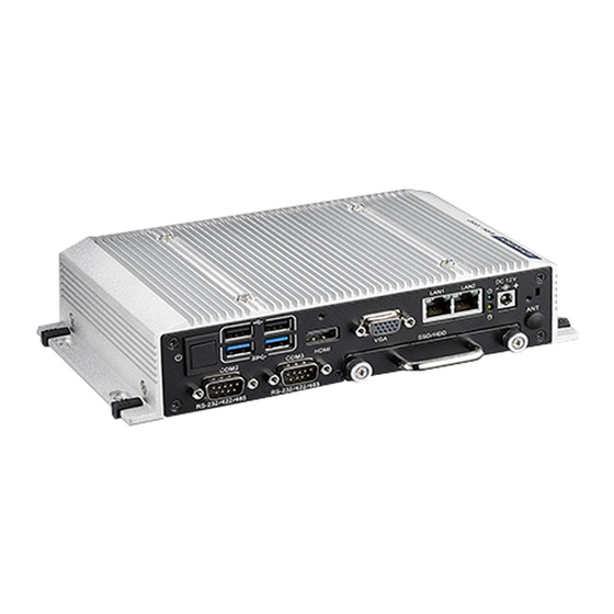
ARK-1550 is a new single board design made very slim. The dimensions are only 223 x 46.6 x 133.0 mm. ARK-1550 can be easily integrated with panel/displays within limited spaces and can be installed anywhere due to its slim dimensions with optional DIN rail and VESA mounting solutions. -
Page 15: Hardware Specification
Audio: Realtek ALC888S, High Definition Audio. Line-out, Mic-in, Line-in Expansion: – 1 x Full-size Mini PCIe slot w/ SIM holder, support mSATA storage or WWAN module – 1 x Half-size Mini PCIe slot, support WLAN module ARK-1550 User Manual... -
Page 16: Mechanical Specification
Mechanical Specification 1.4.1 Dimensions 223 x 46.6 x 133.0 mm (8.69" x 1.81" x 5.18") Figure 1.1 ARK-1550 Mechanical dimension drawing 1.4.2 Weight 1.9 kg (4.18 lbs) Power Requirement 1.5.1 System Power Minimum power input: DC 12 V/5 A 60 W 1.5.2... -
Page 17: Environmental Specification
With mSATA/ SSD: 5 Grms, IEC 60068-2-64, random, 5 ~ 500 Hz, 1 hr/axis 1.6.5 Shock during Operation With mSATA/SSD: 50 G, IEC 60068-2-27, half sine, 11 ms duration 1.6.6 Safety UL, CCC, BSMI, CB 1.6.7 CE/FCC Class A, CCC, BSMI ARK-1550 User Manual... - Page 18 ARK-1550 User Manual...
-
Page 19: Chapter 2 Hardware Installation
Chapter Hardware installation This chapter introduces external IO and the installation of ARK-1550 Hardware. -
Page 20: Introduction
Jumpers 2.2.1 Jumper List The ARK-1550 has a number of jumpers that allow you to configure your system to suit your application. The table below lists the functions of the various jumpers. Jumpers & Switches Auto Power On Setting LCD Power mPCIe &... -
Page 21: Auto Power On Setting (J2)
(2 & 4) Auto Detect (default) Some of mSATA or mPCIe modules can't be recognized correctly through the Auto Detect setting. We suggest you use mSATA or mPCIe setting directly if you meet any compatibility problems. ARK-1550 User Manual... -
Page 22: Clear Cmos (Sw3)
2.2.6 Clear CMOS (SW3) (1-2)* (2-3) Table 2.4: Clear CMOS (SW3) Setting Function (1-2)* Normal (2-3) Clear CMOS ARK-1550 I/O Indication Figure 2.1 ARK-1550 Front View Figure 2.2 ARK-1550 Rear View ARK-1550 User Manual... -
Page 23: Ark-1550 External I/O Connectors
ARK-1550 External I/O Connectors 2.4.1 Power ON/OFF Button ARK-1550 comes with a Power On/Off button, that support dual function of Soft Power -On/Off (Instant off or Delay 4 Second), and Suspend. Figure 2.3 Power ON/OFF Button 2.4.2 Power Input Connector ARK-1550 comes with a DC-Jack header that carries 12 V external power input. -
Page 24: Vga Connector
2.4.5 USB Connectors The ARK-1550 provides up to four USB interface connectors – 2 x USB 2.0 & 2 x USB 3.0, which give complete Plug & Play. The USB interface is compliant with USB UHCI, Rev. 2.0 & 3.0. The USB interface supports Plug and Play, which enables you to connect or disconnect a device whenever you want, without turning off the com- puter. -
Page 25: Audio Connector (Ark-1550F Only)
Audio Signal Name Line-In Line-Out 2.4.7 COM Connector ARK-1550 provides three D-sub 9-pin connectors, which offers 1 x RS-232 & 2 x RS- 232/422/485 serial communication ports (BIOS selectable). COM 1: RS-232 COM 2: RS-232/422/485 COM3: RS-232/422/485 Figure 2.9 COM Port Connector Table 2.9: COM Connector Pin Assignments... -
Page 26: Dio Connector
2.4.8 DIO Connector ARK-1550 offers an 8-bit DIO connector and one ground pin. Each bit of DIO can be set as digital input or output independently. The direction of each bit can be set via Advantech SUSI utility. Figure 2.10 DIO Connector Table 2.10: DIO Connector Pin Assignments... -
Page 27: Led Indicator
2.4.10 LED Indicator There are two LEDs on ARK-1550 front metal face plate for indicating system status: PWR LED is for power status; and HDD LED is for HDD flash disk status. Figure 2.12 LED Indicator 2.4.11 LVDS Connector (Optional) The ARK-1550 comes with a D-Sub 26-pin connector that carries LVDS signal out- put, and can direct connect to LVDS LCD Display via external cable. -
Page 28: Lcd Backlight On/Off Control Connector (Optional)
2.4.12 LCD Backlight On/Off Control Connector (Optional) ARK-1550 comes with a D-Sub 9-pin connector which provides BKLTEN signal as well as +12 V, +5 V and Ground Pin signals that allow the user to connect these sig- nals to the LCD Inverter to implement the LCD On/Off control. -
Page 29: Optional Peripheral Installation
Optional Peripheral Installation 2.5.1 RAM Installation Remove top cover screws * 4pcs and right/left side screws * 4pcs. Remove top cover and locate memory socket. Install memory. (memory is optional, not in standard shipment) ARK-1550 User Manual... -
Page 30: Hdd Installation
Loosen the screws marked in red and take out the hard drive tray. Install the hard drive on the tray (screws are included in the accessory box). Secure the screws on the hard drive tray and push the tray back into the unit. ARK-1550 User Manual... -
Page 31: Msata Installation
(screws are included in accessory box) The WIFI module can be installed in the half-size mini PCIe slot marked in yel- low. (screws are included in the accessory box) Replace the bottom cover and secure the bottom cover screws. ARK-1550 User Manual... - Page 32 ARK-1550 User Manual...
-
Page 33: Chapter 3 Bios Settings
Chapter BIOS settings This chapter introduces how to set BIOS configuration data. -
Page 34: Introduction
Introduction With the AMIBIOS Setup program, you can modify BIOS settings and control the var- ious system features. This chapter describes the basic navigation of the ARK-1550 BIOS setup screens. Figure 3.1 Setup program initial screen AMI's BIOS ROM has a built-in setup program that allows users to modify the basic system configuration. -
Page 35: Entering Setup
System Date using the <Arrow> keys. Enter new values through the keyboard. Press the <Tab> key or the <Arrow> keys to move between fields. The date must be entered in MM/DD/YY format. The time must be entered in HH:MM:SS format. ARK-1550 User Manual... -
Page 36: Advanced Bios Features Setup
3.2.2 Advanced BIOS Features Setup Select the Advanced tab from the ARK-1550 setup screen to enter the Advanced BIOS Setup screen. You can select any of the items in the left frame of the screen, such as CPU Configuration, to go to the sub menu for that item. You can display an Advanced BIOS Setup option by highlighting it using the <Arrow>... -
Page 37: Figure 3.4 Pci Subsystem Settings
This item allows users to enable or disable VGA Palette Snoop. PERR# Generation This item allows users to enable or disable PERR# Generation. SERR# Generation This item allows users to enable or disable SERR# Generation ARK-1550 User Manual... -
Page 38: Figure 3.5 Pci Express Device Register Settings
Link Training Timeout (uS) This item allows users to set the Link Training Timeout (uS) Unpopulated Links This item allows users to set the Unpopulated Links Restore PCIE Registers Enable or disable Restore PCIE Registers ARK-1550 User Manual... -
Page 39: Figure 3.6 Acpi Setting
S3 Video Repost This item allows users to enable or disable VBIOS run after S3 resume. ACPI Low Power S0 Idle This item allows users to enable or disable system wake on alarm event by Items setting. ARK-1550 User Manual... -
Page 40: Figure 3.7 Trusted Computing Configuration
3.2.2.4 Trusted Computing Figure 3.7 Trusted Computing Configuration Security Device Support Enable or disable BIOS support for security device. ARK-1550 User Manual... -
Page 41: Figure 3.8 S5 Rtc Wake Settings
3.2.2.5 S5 RTC Wake Settings Figure 3.8 S5 RTC Wake Settings Wake system with fixed time Enable or disable system wake on alarm event ARK-1550 User Manual... -
Page 42: Figure 3.9 Cpu Configuration Setting
This item allows users to enable or disable intel’s virtualization technology. Hardware Prefetcher This item allows users to enable or disable the hardware prefetcher feature. Adjacent Cache Line Prefetch This item allows users to enable or disable the adjacent cache line prefetch fea- ture. ARK-1550 User Manual... -
Page 43: Figure 3.10Sata Configuration
This item allows users to enable or disable the Hot Plug. External SATA This item allows users to enable or disable the External SATA. SATA Device type This item allows users to select mode of SATA Device type. ARK-1550 User Manual... -
Page 44: Figure 3.11Intel® Rapid Technology
3.2.2.8 Intel® Rapid Start Technology Figure 3.11 Intel® Rapid Technology Intel® Rapid Start Technology This item allows users to enable or disable Rapid Start Technology, if supported. ARK-1550 User Manual... -
Page 45: Figure 3.12Amt Configuration
This item allows users to enable or disable Alert Specification Format. Activate Remote Assistance Process This item allows users to enable or disable trigger CIRA boot. USB Configure This item allows users to enable or disable USB configure function. PET Progress ARK-1550 User Manual... -
Page 46: Figure 3.13Pch-Fw Configuration
OS Timer Set OS watchdog timer. BIOS Timer Set BIOS watchdog timer. 3.2.2.10 PCH-FW Configuration Figure 3.13 PCH-FW Configuration Firmware Update Configuration This item allows users to enable or disable ME FW image re-flash function. ARK-1550 User Manual... -
Page 47: Figure 3.14Usb Configuration
Set the maximum time of the device will take before it properly reports itself to the Host Controller. 'Auto' uses default value: for a Root port it is 100 ms, for a Hub port the delay is taken from Hub descriptor. ARK-1550 User Manual... -
Page 48: Figure 3.15Embedded Controller Configuration
EC Power Saving Mode This item allows users to set board's power saving mode when off. Backlight Mode This item allows users to set backlight Function. EC Watchdog Function This item allows users to select EC watchdog timer. ARK-1550 User Manual... -
Page 49: Figure 3.16Super Io Configuration
This item allows users to configure serial port 1. Serial Port 2 Configuration This item allows users to configure serial port 2. Serial Port 3 Configuration This item allows users to configure serial port 3. ARK-1550 User Manual... -
Page 50: Figure 3.17Serial Port Console Redirection
Figure 3.17 Serial Port Console Redirection Console Redirection This item allows users to enable or disable console redirection for Microsoft Win- dows Emergency Management Services (EMS). Console Redirection This item allows users to configuration console redirection detail settings ARK-1550 User Manual... -
Page 51: Chipset
3.2.3 Chipset Select the Chipset tab from the ARK-1550 setup screen to enter the Chipset BIOS Setup screen. You can display a Chipset BIOS Setup option by highlighting it using the <Arrow> keys. All Plug and Play BIOS Setup options are described in this sec- tion. -
Page 52: Figure 3.19System Agent (Sa) Configuration
3.2.3.1 System Agent (SA) Configuration Figure 3.19 System Agent (SA) Configuration VT-d This item allows users to enable or disable VT-d. ARK-1550 User Manual... -
Page 53: Figure 3.20Intel Igfx Configuration
This item allows users to select DVMT total memory size. – Panel Power Enable This item allows users to enable or disable Panel Power. Graphics Perfor- mance. – Analyzers This item allows users to enable or disable Graphics Performance Analyzers. ARK-1550 User Manual... -
Page 54: Figure 3.21Lcd Control
LCD Control Figure 3.21 LCD Control Primary IGFX Boot Display Select boot display device at post stage. LVDS This item allows user to enable or disable LVDS LCD Panel Type This item allows users to select panel resolution. ARK-1550 User Manual... -
Page 55: Figure 3.22Memory Configuration
Memory Configuration Figure 3.22 Memory Configuration – Memory Information This item shows memory configuration parameters. ARK-1550 User Manual... -
Page 56: Figure 3.23Pch-Io Configuration
Enable or disable USB to wake the system from S4. SLP_S4 Assertion Width This item allows users to set a delay of sorts. Restore AC Power Loss This item allows users to select off, on and last state. ARK-1550 User Manual... -
Page 57: Figure 3.24Pci Express Configuration
Glitch W/A for bad USB device(s) connected behind PCIE/PEG Port. – Subtractive Decode This item allows users to enable or disable Subtractive Decode. – PCI Express Root Port 1/2/3/6 This item allows users to configure PCI Express Root port 1/2/3/6 setting. ARK-1550 User Manual... -
Page 58: Figure 3.25Usb Configuration
This item allows users to enable or disable trunk clock gating. – USB Ports Per-Port Disable Control This item allows users to enable or disable USB Ports Per-Port Disable Con- trol. Control each of the USB ports (0~13) disabling ARK-1550 User Manual... -
Page 59: Figure 3.26Pch Azalia Configuration
Azalia This item allows users to change Azalia settings. – Control detection of the Azalia device. Disable- Azalia will be unconditionally Disabled Enabled- Azalia will be unconditionally Enabled Auto- Azalia will be enabled if present, disabled otherwise. ARK-1550 User Manual... -
Page 60: Boot Settings
This item allows users to set the system boot order. Hard Drive BBS Priorities This item allows users to set the order of the legacy devices in this group. CSM Support This item allows users to enable or disable CSM support. ARK-1550 User Manual... -
Page 61: Security Setup
To access the sub menu for the following items, select the item and press <Enter>: Change Administrator / User Password: Select this option and press <ENTER> to access the sub menu, and then type in the password. ARK-1550 User Manual... -
Page 62: Save & Exit
Restore Defaults The ARK-1550 automatically configures all setup items to optimal settings when users select this option. Optimal Defaults are designed for maximum system performance, but may not work best for all computer applications. In particular, do not use the Optimal Defaults if the user's computer is experiencing system configuration problems. - Page 63 When users have completed system configuration, select this option to save changes as user defaults without exit BIOS setup menu. Restore User Defaults The users can select this option to restore user defaults. Boot Override This item allows users to choose boot device. ARK-1550 User Manual...
- Page 64 ARK-1550 User Manual...
-
Page 65: Wdt Sample Code
Appendix WDT Sample Code... -
Page 66: Watchdog Timer Sample Code
EC_ EC_Data_Port mov al, 57h ; Watch dog event flag. out dx,al mov dx, EC_Data_Port mov al, 04h ; Reset event. out dx,al mov dx, EC_Command_Port mov al,28h ; start WDT function. out dx,al .exit ARK-1550 User Manual... - Page 67 ARK-1550 User Manual...
- Page 68 No part of this publication may be reproduced in any form or by any means, electronic, photocopying, recording or otherwise, without prior written permis- sion of the publisher. All brand and product names are trademarks or registered trademarks of their respective companies. © Advantech Co., Ltd. 2017...
Need help?
Do you have a question about the ARK-1550 and is the answer not in the manual?
Questions and answers