Table of Contents
Advertisement
Quick Links
Advertisement
Table of Contents

Related Manuals for Advantech ARK-2120


Summary of Contents for Advantech ARK-2120
- Page 1 User Manual ARK-2120 Fanless Embedded Box PC...
- Page 2 English user manual included as a PDF file on the CD. Please disregard the Chinese hard copy user manual if the product is not to be sold and/or installed in China. ARK-2120 User Manual...
- Page 3 The documentation and the software included with this product are copyrighted 2010 by Advantech Co., Ltd. All rights are reserved. Advantech Co., Ltd. reserves the right to make improvements in the products described in this manual at any time without notice.
-
Page 4: Declaration Of Conformity
Because of Advantech’s high quality-control standards and rigorous testing, most of our customers never need to use our repair service. If an Advantech product is defec- tive, it will be repaired or replaced at no charge during the warranty period. For out- of-warranty repairs, you will be billed according to the cost of replacement materials, service time and freight. -
Page 5: Technical Support And Assistance
Technical Support and Assistance Visit the Advantech web site at www.advantech.com/support where you can find the latest information about the product. Contact your distributor, sales representative, or Advantech's customer service center for technical support if you need additional assistance. Please have the following information ready before you call: –... -
Page 6: Ordering Information
Power cable 2-pin 180 cm, USA for ARK-338X 1700001948 Power cable 2-pin 180 cm, Europe for ARK-338X 1700001949 Power cable 2-pin 180 cm, UK for ARK-338X 1700009001 2-Pole Phoenix to DC-Jack Power cable 9666K10000E DIN-rail mounting kit 1960025333N00N VESA mounting kit ARK-2120 User Manual... -
Page 7: Safety Instructions
RESTRICTED ACCESS AREA: The equipment should only be installed in a Restricted Access Area. DISCLAIMER: This set of instructions is given according to IEC 704-1. Advan- tech disclaims all responsibility for the accuracy of any statements contained herein. ARK-2120 User Manual... - Page 8 ARK-2120 User Manual viii...
-
Page 9: Table Of Contents
Chipset ...................... 4 1.3.1 Functional Specification ..............4 1.3.2 iManager ..................5 Mechanical Specifications................. 6 1.4.1 Dimensions ................... 6 Figure 1.1 ARK-2120 Mechanical dimension drawing....6 1.4.2 Weight................... 6 Power Requirement .................. 6 1.5.1 System Power................6 1.5.2 RTC Battery .................. 6 Environment Specification................. - Page 10 3.3.1 System date / System time ............29 Advanced BIOS Features Setup............. 30 Figure 3.3 Advanced BIOS features setup screen ....30 3.4.1 Advantech BIOS Update V1.3 ............ 30 3.4.2 ACPI Settings ................31 Figure 3.4 ACPI Setting............. 31 3.4.3 TPM Configuration..............
- Page 11 Discard Changes ................ 44 3.8.7 Restore Defaults ................. 44 3.8.8 Save User Defaults ..............44 3.8.9 Restore User Defaults..............44 3.8.10 Boot Override................44 Appendix A Watchdog Timer Sample Code..45 EC Watchdog Timer sample code ............46 ARK-2120 User Manual...
- Page 12 ARK-2120 User Manual...
-
Page 13: Chapter 1 General Introduction
Chapter General Introduction This chapter gives background information on ARK-2120 series. -
Page 14: Introduction
12V to 24V, wide temperature range -20 ~ 60° C, diverse expandability options, and structural strengthening. ARK-2120 enlarges the surface of the top cover and con- ductive cylinder to create maximum cooling effects for optimized cooling efficiency. It also provides rich I/O interfaces: up to 6 x USBs, 3 x GbEs, 6 x COMs, and supports high capacity 2.5”... -
Page 15: Product Features
Storage: 1 x Cfast and 1 x high capacity 2.5” SATA HDD (up to 12.5mm height) Expansion Interface: Supports 1 x Mini-PCI with SIM holder Software API: Advantech iManager and SUSIAccess - Remote Device Man- agement technology 1.2.2 Display ®... -
Page 16: Chipset
All ports are High-Speed, Full-Speed, and Low-Speed capable Supports legacy keyboard/mouse software Intel® NM10 chip supports: Power APM1.2, ACPI supports Management Power state: S0, S3, S4, S5 Intel® NM10 chip supports: BIOS AMI 16Mb Flash BIOS via SPI ARK-2120 User Manual... -
Page 17: Imanager
Sequence control Supported 8-bit programmable DIO Watchdog timer Multi Level WDT (set by Advantech iManager) Programmable 1-255 sec / min Hardware monitor CPU Temperature / input Current / input Voltage Power saving Deep sleep S5 mode / Smart Fan / Back light control... -
Page 18: Mechanical Specifications
Dimensions 264.5[10.41] x 68.4[2.69] x 133.0[5.2] Unit: mm [Inch] Detail A Ø4,6 238,2 68.39 252,5 Detail A 264,5 Figure 1.1 ARK-2120 Mechanical dimension drawing 1.4.2 Weight 2.5 kg (5.51 lb) Power Requirement 1.5.1 System Power Minimum power input: –... -
Page 19: Environment Specification
~ 500 Hz, 1hr/axis, x,y,z 3 axes. 1.6.5 Shock during Operation When system is equipped with SSD/Cfast: 50G, IEC 60068-2-27, half sine, 11 ms duration. 1.6.6 Safety UL, CCC, BSMI 1.6.7 CE, FCC, CCC, BSMI ARK-2120 User Manual... - Page 20 ARK-2120 User Manual...
-
Page 21: Chapter 2 H/W Installation
Chapter H/W Installation This chapter introduces external IO and the installation of ARK- 2120 hardware. -
Page 22: Introduction
2.2.1 Jumper Description You may configure the ARK-2120 to match the needs of your application by setting jumpers. A jumper is a metal bridge used to close an electric circuit. It consists of two metal pins and a small metal clip (often protected by a plastic cover) that slides over the pins to connect them. -
Page 23: Jumper List
2.2.2 Jumper List Table 2.1: Jumper List of Main Board 48-bit LVDS Power (F version only) Auto Power on setting COM2 Setting (F version only) Clear CMOS 2.2.3 Jumper Location Figure 2.1 Jumper layout (Component Side) ARK-2120 User Manual... -
Page 24: Jumper Setting
Function (1-3)* +3.3V (default) (3-5) (3-4) +12V Auto Power On Setting Part Number 1653002101 Footprint HD_3x2P_79_D Description PIN HEADER 2*1P 180D(M)SQUARE 2.0mm DIP W/O Pb Setting Function Power On by power button (1-2)* Auto Power On (default) ARK-2120 User Manual... -
Page 25: Connectors
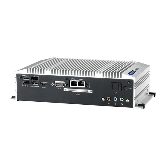
1653003101 Footprint HD_3x1P_79_D Description PIN HEADER 3x1P 2.0mm 180D(M) DIP 2000-13 WS Setting Function (1-2)* Normal (default) (2-3) Clear COMS Connectors 2.3.1 ARK-2120 External I/O Connectors ARK-2120L: LAN1 LAN2 USB1 USB3 PWR LED LINE-OUT ON/OFF LAN1 HDMI VGA CFast LAN2... -
Page 26: Figure 2.4 Ark-2120F Io Connectors Drawing
2.3.1.1 COM Connector ARK-2120 provides up to six D-sub 9-pin connectors, which offers RS-232/422/485 serial communication interface ports. Default setting is RS-232, if you want to use RS-422/485, you can find the jumper installation in Chapter 2.2.4 for ARK-2120L and BIOS setting in Chapter 3.4.9. -
Page 27: Table 2.2: Com Connnector Pin Assignments
2.3.1.2 Ethernet Connector (LAN) ARK-2120 is equipped up to three Ethernet controllers that are fully compliant with IEEE 802.3u 10/100/1000 Mbps CSMA/CD standards. LAN1, LAN2 and LAN3 are all equipped with Intel 82583V Ethernet controller. The Ethernet port provides a stan- dard RJ-45 jack connector with LED indicators on the front side to show its Active/ Link status (Green LED) and Speed status (Yellow LED). -
Page 28: Figure 2.7 Audio Connector
2.3.1.3 Audio Connector ARK-2120 offers stereo audio ports by three phone jack connectors of Line_Out, Line_In, Mic_In. The audio chip is controlled by ALC892, and it’s compliant with Aza- lea standard. Figure 2.7 Audio connector Table 2.4: Audio Connector Pin Assignments... -
Page 29: Figure 2.9 Dio Connector (Ark-2120F)
2.3.1.5 USB Connector ARK-2120 provides up to six USB interface connectors, which give complete Plug & Play and hot swapping for up to 127 external devices. The USB interface complies with USB UHCI, Rev. 2.0 compliant. The USB interface can be disabled in the system BIOS setup. -
Page 30: Figure 2.11Vga Connector
2.3.1.6 VGA Connector The ARK-2120 provides a high resolution VGA interface connected by a D-sub 15- pin connector to support a VGA CRT monitor. It supports display resolution up to 1900 x 1200. Figure 2.11 VGA Connector Table 2.8: VGA Connector Pin Assignments... -
Page 31: Figure 2.14Power Input Connector (Ark-2120F)
Figure 2.15 Power Button 2.3.1.9 LED Indicators There are two LEDs on ARK-2120 front metal face plate for indicating system status: PWR LED is for power status; and HDD LED is for HDD & Cfast flash disk status. Figure 2.16 LED Indicators 2.3.1.10... -
Page 32: Table 2.10: Lvds Connector Pin Assignment
2.3.1.11 LCD Backlight On/Off control Connector (ARK-2120F only) The ARK-2120 comes with a D-Sub 9-pin connector which provides BKLTEN signal as well as +12 V, +5 V and Ground Pin signals that allow the user to connect these signals to LCD Inverter to implement the LCD On/Off control. -
Page 33: Installation
Installation 2.4.1 HDD Installation Unscrew the six screws on the bottom cover. Slide the 2.5" SATA HDD into the HDD bay on the bottom cover. ARK-2120 User Manual... -
Page 34: Memory Installation
Screw the four screws on the side of HDD bracket. The screws are used to fix the HDD on the bracket. (The screws are in the accessory box.) Recover the bottom cover and screws. 2.4.2 Memory Installation Unscrew the four screws on the top cover. ARK-2120 User Manual... - Page 35 Unscrew the four screws on the right and left side of top cover Remove the top cover Install DDR3 memory in to the system Recover the top chassis. ARK-2120 User Manual...
-
Page 36: Cfast Installation
2.4.3 CFast Installation Unscrew the two screws on the CFast door. Pull the CFast tray out. Remove the dummy CFast bracket. ARK-2120 User Manual... - Page 37 Put CFast on to the CFast tray. Push the CF tray back and secure with screws. ARK-2120 User Manual...
- Page 38 ARK-2120 User Manual...
-
Page 39: Bios Settings
Chapter BIOS Settings... -
Page 40: Bios Setup
AMIBIOS has been integrated into many motherboards for over a decade. With the AMIBIOS setup program, you can modify BIOS settings and control the various sys- tem features. This chapter describes the basic navigation of the ARK-2120 BIOS setup screens. -
Page 41: Main Setup
Date using the <Arrow> keys. Enter new values through the keyboard. Press the <Tab> key or the <Arrow> keys to move between fields. The date must be entered in MM/DD/YY format. The time must be entered in HH:MM:SS format. ARK-2120 User Manual... -
Page 42: Advanced Bios Features Setup
This item allows users to flash BIOS. Please save the new BIOS in a USB pen drive and rename its file name as "update.bin". Plug the pen drive on ARK-2120 and boot into the BIOS setting. Then select this item, the system will update the new BIOS automatically. -
Page 43: Acpi Settings
This item allows users to set the ACPI sleep state. Lock Legacy Resources This item allows users to lock legacy devices' resources. S3 Video Report This item allows users to enable or disable S3 resume for VBIOS. ARK-2120 User Manual... -
Page 44: Tpm Configuration
3.4.3 TPM Configuration Figure 3.5 TPM Configuration TPM Support Disable/Enable TPM if available. 3.4.4 CPU Configuration Figure 3.6 CPU Configuration ARK-2120 User Manual... -
Page 45: Sata Configuration
This item allows users to enable or disable limit CPUID maximum for Windows 3.4.5 SATA Configuration Figure 3.7 SATA Configuration SATA Controller(s) This item allows users to enable or disable the SATA controller(s). SATA Mode Selection This item allows users to select mode of SATA controller(s). ARK-2120 User Manual... -
Page 46: Intel Fast Flash Standby
3.4.6 Intel Fast Flash Standby Figure 3.8 Intel Fast Flash Standby IFFS Support This item allows users to enable or disable iFFS. 3.4.7 USB Configuration Figure 3.9 USB Configuration ARK-2120 User Manual... -
Page 47: Embedded Controller Configuration
This item allows users to enable or disable smart FAN feature. Backlight Enable Polarity (F version only) This item allows users to set backlight enable polarity. EC Watch Dog Function This item allows users to enable or disabled EC watchdog function. ARK-2120 User Manual... -
Page 48: Super I/O Configuration
This item allows users to configure serial port 1. Serial Port 2 Configuration This item allows users to configure serial port 2. Serial Port 3 Configuration This item allows users to configure serial port 3. ARK-2120 User Manual... -
Page 49: Aoac Configuration
3.4.10 AOAC Configuration Figure 3.12 AOAC Configuration AOAC Configuration This item allows users to enable or disabled AOAC function. 3.4.11 PPM Configuration Figure 3.13 PPM Configuration ARK-2120 User Manual... -
Page 50: Chipset Configuration
This item allows users to enable or disabled Intel C-state POPUP function. Chipset Configuration Select the Chipset tab from the ARK-2120 setup screen to enter the Chipset BIOS Setup screen. You can display a Chipset BIOS Setup option by highlighting it using the <Arrow>... -
Page 51: Host Bridge/Intel Igd Configuration
This item allows users to select ASL support for ACPI. Backlight Control Support (F version only) This item allows users to select backlight control support. BIA (F version only) This item allows users to select BIA with selected aggressiveness level. ARK-2120 User Manual... -
Page 52: South Bridge
3.5.2 South Bridge Figure 3.16 South Bridge Figure 3.17 TPT Device Azalia Controller Enables or disables the azalia controller. ARK-2120 User Manual... -
Page 53: Boot Settings
High Precision Timer Enables or disables the high precision timer. SLP_S4 Assertion Width This item allows users to set a delay of sorts. Restore AC Power Loss Boot Settings Figure 3.18 Boot Setup Utility ARK-2120 User Manual... -
Page 54: Security Setup
Security Setup Figure 3.19 Password Configuration Select Security Setup from the ARK-2120 Setup main BIOS setup menu. All Security Setup options, such as password protection is described in this section. To access the sub menu for the following items, select the item and press <Enter>: ... -
Page 55: Save & Exit
Select this option to quit Setup without making any permanent changes to the system configuration and reboot the computer. 3.8.5 Save Changes When users have completed system configuration, select this option to save changes without exiting the BIOS setup menu. ARK-2120 User Manual... -
Page 56: Discard Changes
3.8.7 Restore Defaults The ARK-2120 automatically configures all setup items to optimal settings when users select this option. Optimal Defaults are designed for maximum system perfor- mance, but may not work best for all computer applications. In particular, do not use the Optimal Defaults if the user's computer is experiencing system configuration problems. -
Page 57: Appendix A Watchdog Timer Sample Code
Appendix Watchdog Timer Sample Code... -
Page 58: Ec Watchdog Timer Sample Code
EC_Command_Port mov al, 57h ; Watch dog event flag. out dx,al mov dx, EC_Data_Port mov al, 04h ; Reset event. out dx,al mov dx, EC_Command_Port mov al,28h ; start WDT function. out dx,al .exit ARK-2120 User Manual... - Page 59 ARK-2120 User Manual...
- Page 60 No part of this publication may be reproduced in any form or by any means, electronic, photocopying, recording or otherwise, without prior written permis- sion of the publisher. All brand and product names are trademarks or registered trademarks of their respective companies. © Advantech Co., Ltd. 2012...
Need help?
Do you have a question about the ARK-2120 and is the answer not in the manual?
Questions and answers