Table of Contents
Advertisement
Quick Links
Advertisement
Table of Contents

Related Manuals for Advantech ARK-1382


Summary of Contents for Advantech ARK-1382
- Page 1 User Manual ARK-1382...
- Page 2 No part of this manual may be reproduced, copied, translated or transmitted in any form or by any means without the prior written permission of Advantech Co., Ltd. Information provided in this manual is intended to be accurate and reliable. How- ever, Advantech Co., Ltd.
-
Page 3: Technical Support And Assistance
Technical Support and Assistance Visit the Advantech web site at www.advantech.com/support where you can find the latest information about the product. Contact your distributor, sales representative, or Advantech's customer service center for technical support if you need additional assistance. Please have the following information ready before you call: –... - Page 4 ARK-1382 User Manual...
-
Page 5: Table Of Contents
Jumper Setting................11 2.1.3 Locating Jumpers on the Board ..........13 Connectors....................14 Figure 2.1 ARK-1382 Front Side External I/O Connectors ..14 Figure 2.2 ARK-1382 Rear Side External I/O Connectors..14 2.2.1 ARK-1382 Front Side External I/O Connectors ......15 Figure 2.3 COM Connector............ - Page 6 Figure 4.11Jumper Setting ............39 Figure 4.12Install the board on the bottom side and be careful for thermal pad .............. 40 Appendix A Realtek RTL8111B/8111C Gigabit Boot Agent Configuration Menu41 Realtek RTL8111B/8111C Gigabit Boot Agent Configuration Menu ..42 ARK-1382 User Manual...
-
Page 7: Chapter 1 General Introduction
Chapter General Introduction... -
Page 8: Introduction
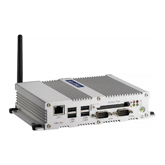
Introduction ARK-1382 is a fanless and ultra compact system designed for a wide range of appli- cations, such as Point of information system, flight information display system, and vehicle video player system. ARK-1382 designed with Intel Celeron M 423 @ 1.06 GHz, which provides the excel- lent computing and multimedia performance. -
Page 9: Product Feature
Resolution: CRT Display mode: pixel resolution up to 1600 x 1200 at 85-Hz and 1600 x 1200 at 75-Hz LCD Display mode: Display Interface: 2 x DVI-I, (VGA interface can be extended by connector) Dual Independent: DVI + DVI; DVI + VGA; (VGA +VGA only supports clone mode) ARK-1382 User Manual... -
Page 10: Chipset
Supports maximum 1GB DDR SDRAM. Memory SO-DIMM Socket on board: 200 pin SO-DIMM socket type x 1 It may have compatibility issue for 2 GB memory, please check with Advantech support team. NB: Intel 945GM GMCH chip supports: Internal Graphics Features... - Page 11 Power connecter: Plug-In block 2P DIP x 1 SB: Intel NH82801GHM chip supports: Low Pin Count (LPC) interface support Firmware Hub (FWH) interface support BIOS Phoenix 4M bit Flash BIOS, supports Plug & Play, APM 1.2/ACPI 1.1. Socket: 32 pin PLCC socket x 1 ARK-1382 User Manual...
- Page 12 DVI-I Connector on board: DVI-I Combined Conn. 29P 90D(F) x 2 Video Amplifier: Linear LT6557 x 2 Supports Dual VGA Display via Video Separate Amplifier Share with DVI-I Connector on board: DVI-I Combined Conn. 29P 90D(F) x 2 ARK-1382 User Manual...
-
Page 13: Mechanical Specification
Supports Mini PCI Interface 1.0 (Optional) Supports 802.11 b/g Mini PCI socket: MINI PCI 124P 180D(F) SMD x 1 1.3.2 Mechanical Specification 1.3.2.1 Dimension (mm) 189 x 41 x 130.6mm (7.44” x 1.61” x 5.14”) Unit: mm Figure 1.1 ARK-1382 Dimensions ARK-1382 User Manual... -
Page 14: Electrical Specification
Operating Humidity: 0% ~ 90% Relative Humidity, non-condensing 1.3.4.3 Storage Temperature Standard products (0 ~ 60° C) Storage temperature: -20 ~ 70° C 1.3.4.4 Storage Humidity Standard products (0 ~ 60° C) Relative humidity: 95% @ 60° C ARK-1382 User Manual... -
Page 15: Chapter 2 H/W Installation
Chapter H/W Installation... -
Page 16: Jumpers
Warning! To avoid damaging the computer, always turn off the power supply before setting jumpers. Clear CMOS. Before turning on the power sup- ply, set the jumper back to 3.0 V Battery On. ARK-1382 User Manual... -
Page 17: Jumper Setting
2.1.2 Jumper Setting 2.1.2.1 COM1 Jumper ARK-1382 series of embedded box computer provide a jumper - JP1 ~ JP3 located on the internal carrier board for COM1 selecting the RS-232, RS422 and RS485. Close pins Function RS-232* RS-232* RS-422/RS-485 RS422/RS-485 (*): means default setting of the jumper/function. - Page 18 (*): means default setting of the jumper/function. 2.1.2.3 CMOS Jumper (JP8) ARK-1382 series of embedded box computer provide a jumper - JP8 located on the internal carrier board for selecting the CMOS of Clear or Normal status. Close pins Function...
-
Page 19: Locating Jumpers On The Board
2.1.3 Locating Jumpers on the Board ARK-1382 User Manual... -
Page 20: Connectors
Connectors Normal LED HDD LED Compact Flash Alarm LED PWR LED USB4 USB2 USB3 USB1 ON/OFF COM2 COM1 Figure 2.1 ARK-1382 Front Side External I/O Connectors GN D Figure 2.2 ARK-1382 Rear Side External I/O Connectors ARK-1382 User Manual... -
Page 21: Ark-1382 Front Side External I/O Connectors
2.2.1.2 USB Connector ARK-1382 provides four connectors of USB interface, which give complete Plug & Play and hot swapping for up to 127 external devices. The USB interface complies with USB UHCI, Rev. 2.0 compliant. The USB interface can be disabled in the system BIOS setup. -
Page 22: Table 2.2: Usb Connector
Table 2.3: RJ-45 Connector Pin Assignments 10/100/1000BaseT Signal Name 2.2.1.4 Compact Flash Card ARK-1382 is equipped with an external CF card. You can find the installation in Appendix. 2.2.1.5 Power ON/OFF Button ARK-1382 comes with a Power On/Off button, that support dual function of Soft Power -On/Off (Instant off or Delay 4 Second), and Suspend. -
Page 23: Ark-1382 Rear Side External I/O Connectors
2.2.2.1 DVI-I Connector ARK-1382 provides dual DVI-I interface, you can link your DVI monitor and ARK- 1382 support dual independent display. For VGA monitor, you can use the DVI-I to VGA connector in the package (Advantech P/N: 1654000446), support dual indepen- dent display for DVI + VGA;... -
Page 24: Figure 2.7 Esata/Usb Connector
2.2.2.3 USB5/eSATA ARK-1382 provides external SATA connector for external storage; if you do not need to use eSATA, the connector can be used as USB port. Figure 2.7 eSATA/USB Connector Table 2.5: eSATA/USB Connector Pin Assignment Signal name VBUS SATA_TX+... -
Page 25: Chapter 3 Bios Operation
Chapter BIOS Operation Sections include: BIOS Introduction BIOS Setup... -
Page 26: Bios Introduction
Intel CPUs from 386 through to Pentium, and AMD Geode to K7 and K8; as well as nVidia and VIA processors. Advantech also provides utilities to easily select and install features that suit the cus- tomers’ own designs. -
Page 27: Main Menu
This option loads values that are optimized for stable, average performance. Set Password Establish, change, or disable passwords. Save & Exit Setup Save CMOS value settings to CMOS and exit BIOS setup. Exit Without Saving Abandon all CMOS value changes and exit BIOS setup. ARK-1382 User Manual... -
Page 28: Standard Cmos Features
Extended Memory The BIOS POST displays the amount of extended memory (above 1 MB in the CPU's memory address map) installed in the system. Total Memory This item displays the total system memory size. ARK-1382 User Manual... -
Page 29: Advanced Bios Features
3.2.3 Advanced BIOS Features Blank Boot [Disabled] (* Advantech feature enhancement) When enabled, the system displays a blank screen during the BIOS POST stage. POST Beep [Enabled] (* Advantech feature enhancement) When enabled, the system emits beep sounds during the BIOS POST stage. - Page 30 Full Screen Logo Show [Enabled] Shows full screen logo during POST stage; logo image can be customized. Small Logo (EPA) Show [Disable] Shows EPA logo during system POST stage. Summary Screen Show [Enabled] Shows system status on summary screen page. ARK-1382 User Manual...
-
Page 31: Advanced Chipset Features
This item allows the user to select whether onboard graphics processor or the PCI Express card. On-Chip Frame Buffer Size [8 MB] This item allows the user to choose Frame Buffer Size. BIOS default value is set to 8 MB. ARK-1382 User Manual... -
Page 32: Integrated Peripherals
This item allows the selection for the mode of operation of the serial port. – Onboard Parallel Port [378/IRQ7] This item allows the user to change the parallel port address. BIOS default value is set to .378/IRQ7.. ARK-1382 User Manual... -
Page 33: Power Management Setup
V/H SYNC+Blank This option will cause the system to turn off vertical and horizontal synchronization ports and write blanks to the video buffer. – Blank Screen This option only writes blanks to the video buffer. – DPMS Initial displays power management signaling. ARK-1382 User Manual... - Page 34 This item allows users to power on the system at a specified date and/or time. – Disabled Disable this function. – Enabled Enable alarm function to power on system – Data (of month) Alarm1-31 – Time (HH:MM:SS) Alarm(0-23) : (0-59) : 0-59) ARK-1382 User Manual...
-
Page 35: Pnp/Pci Configurations
Current System/CPU Temp [Show Only] This item displays current system and CPU temperature. 2.5 V / 3.3 V / 5 V / 12 V and VCore [Show Only] This item displays current CPU and system Voltage. ARK-1382 User Manual... -
Page 36: Frequency/Voltage Control
Load Optimized Defaults loads the default system values directly from ROM. If the stored record created by the Setup program should ever become corrupted (and therefore unusable). These defaults will load automatically when you turn the ARK-1382 Series system on. ARK-1382 User Manual... -
Page 37: Set Password
Select Set Password again, and at the “Enter Password” prompt, don’t enter anything; just press <Enter>. At the “Confirm Password” prompt, again, don’t type in anything; just press <Enter>. Select Save to CMOS and EXIT, type <Y>, then <Enter>. ARK-1382 User Manual... -
Page 38: Save & Exit Setup
Type “Y” will quit the BIOS Setup Utility and save user setup value to CMOS. Type “N” will return to BIOS Setup Utility. 3.2.13 Exit Without Saving Note! Type “Y” will quit the BIOS Setup Utility without saving to CMOS. Type “N” will return to BIOS Setup Utility. ARK-1382 User Manual... - Page 39 Chapter Full Disassembly Procedure...
-
Page 40: Introduction
If you want to completely disassemble ARK-1382, follow the step-by-step procedures below. Users should be aware that Advantech Co., Ltd. takes no responsibility what- soever for any problems or damage caused by the user disassembly of ARK-1382. Make sure the power cord of ARK-1382 is unplugged before you start disassembly. -
Page 41: Figure 4.2 Unscrew The 6 Screws On The Front Side Frame
Unscrew the 6 screws on the front side frame. Figure 4.2 Unscrew the 6 screws on the front side frame Unscrew the 1 screws on the front face plate. Figure 4.3 Unscrew the 1 screws on the front face plate ARK-1382 User Manual... -
Page 42: Figure 4.4 Unscrew The 4 Hex-Bolt On The Front Face Plate
Unscrew the 4 Hex-bolt on the front face plate. Figure 4.4 Unscrew the 4 Hex-bolt on the front face plate Unscrew the 6 screws on the rear side frame. Figure 4.5 Unscrew the 6 screws on the rear side frame ARK-1382 User Manual... -
Page 43: Figure 4.6 Unscrew The 4 Hex-Bolt On The Rear Face Plate
Unscrew the 4 Hex-bolt on the rear face plate. Figure 4.6 Unscrew the 4 Hex-bolt on the rear face plate Unscrew the antenna mounting screw. Figure 4.7 Unscrew the antenna mounting screw ARK-1382 User Manual... -
Page 44: Figure 4.9 Memory Socket
Pull out the carrier board from the Aluminum case on bottom side, and be care- ful for the thermal pad. Figure 4.8 Pull out the carrier board from the Aluminum case on bottom side, and be careful for the thermal pad Memory socket. Figure 4.9 Memory Socket ARK-1382 User Manual... -
Page 45: Figure 4.10Minipci Socket
MiniPCI socket. Figure 4.10 MiniPCI Socket Jumper setting. Figure 4.11 Jumper Setting ARK-1382 User Manual... -
Page 46: Figure 4.12Install The Board On The Bottom Side And Be Careful For Thermal Pad
Install the board on the bottom side and be careful for thermal pad. Figure 4.12 Install the board on the bottom side and be careful for thermal pad ARK-1382 User Manual... - Page 47 Appendix Realtek RTL8111B/ 8111C Gigabit Boot Agent Configuration Menu...
-
Page 48: A.1 Realtek Rtl8111B/8111C Gigabit Boot Agent Configuration Menu
When user need for the boot from LAN application, you can press the Shift + F10 to enter Boot Agent Setup Menu to setting during the system initialization. The Intel Boot Agent Provide the two of Network Boot protocols (PXE and RPL), user can choose it on Network Boot Protocol item. ARK-1382 User Manual... - Page 49 This Transmitter must not be co-located or operating in conjunction with any other antenna or transmitter. This equipment complies with FCC RF radiation exposure limits set forth for an uncontrolled environment. This equipment should be installed and operated with a minimum distance of 20 centimeters between the radiator and your body. ARK-1382 User Manual...
- Page 50 No part of this publication may be reproduced in any form or by any means, electronic, photocopying, recording or otherwise, without prior written permis- sion of the publisher. All brand and product names are trademarks or registered trademarks of their respective companies. © Advantech Co., Ltd. 2008...
Need help?
Do you have a question about the ARK-1382 and is the answer not in the manual?
Questions and answers