
Related Manuals for American Time DSY261RSAE


Summary of Contents for American Time DSY261RSAE
- Page 1 Installation and Operation Manual DSY261RSAE Digital Clock/Elapsed Time Indicator with Code Blue Part # H004423 Rev. 5 October 2011...
- Page 2 Electrical Shock Hazard DSY261RSAE Owner's Manual WARNING: Hazardous voltage in electrical equipment can cause severe personal injury or death. Inspection, installation, and preventive maintenance should only be performed on equipment to which power has been turned off, disconnected and electrically isolated so no accidental contact can be made with energized parts.
-
Page 3: Table Of Contents
Appendix 1: Wiring For 3-Wire Secondary Clocks.....................16 Appendix 2: Wiring For 4-Wire Secondary Clocks.....................17 Appendix 3: Using the DSY261RSAE as an Up Counting 1 Elapsed Timer Only ............18 Appendix 4: Using the DSY261RSAE as a Down Counting, Elapsed Timer Only ............18 Appendix 5: Operators Flowchart ..........................19... -
Page 4: Important Installation And Warranty Information
DSY261RSAE Owner's Manual IMPORTANT INSTALLATION AND WARRANTY INFORMATION WARRANTY INFORMATION: American Time (the Manufacturer) provides a limited warranty to the Original Purchaser of this product. The Original Purchaser is the party to whom the Manufacturer issued its Sales Order, generally the Manufacturer’s distributor. -
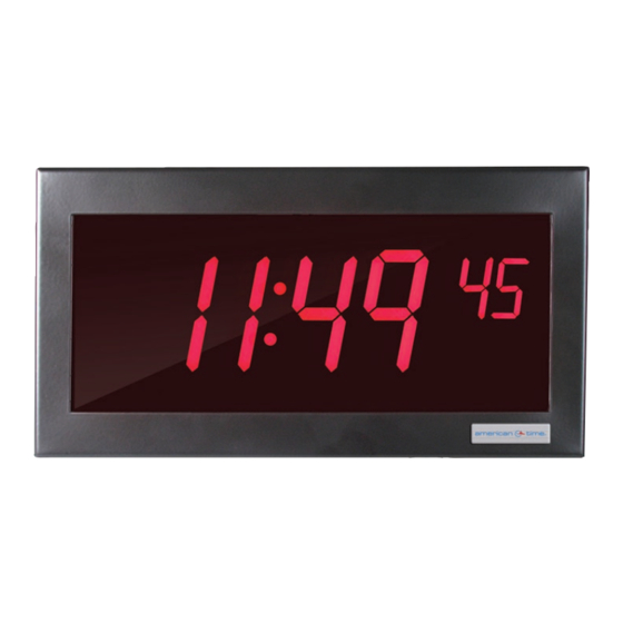
Page 5: Specifications
Specifications DSY261RSAE Owner's Manual GENERAL Weight: ......Digital Clock/Timer ....... 4.27 lb........ATSTCS Control Station ......0.27 lb. External Dimensions: ..Digital Clock/Timer ....... 5.375" X 12.375" X 3" .......ATSTCS Control Station ......4.63" X 4.56" X 1.25" SPECIFICATIONS ELECTRICAL Power Requirements (Digital Clock/Timer only): Line Voltage: .................. -
Page 6: Description
The DSY261RSAE can also be wired as a 12-hour secondary clock. When combined with the ATSTCS Control Station, the DSY261RSAE can also be used as an up or down counting elapsed timer. The elapsed timers can be started, stopped, resumed, and reset. Both timer modes have a programmable preset value. -
Page 7: Atstcs Control Station
Control Station Switch Functions DSY261RSAE Owner's Manual Run/Set Switch - Set Position: This position is used to set a preset up or down counting time (Timer). It is also used to reset the Code Blue timer. This position is not used for setting time. The controller will allow you to enter in a 12/24 hour mode and set a time. -
Page 8: Installation Instructions
Clock/Timer Installation DSY261RSAE Owner's Manual The Digital Clock/Timer can be mounted to a single or double gang box. To install the Digital Clock/Timer, follow the instructions below. Ensure that installation conforms to the National Electrical Code and local wiring codes. -
Page 9: Atstcs Installation Instructions
Control Station Installation DSY261RSAE Owner's Manual The ATSTCS Control Station can be mounted to a double gang box, 1 inch deep or deeper. The Control Station can be mounted up to 30 feet away from the Digital Clock/Timer. The recommended minimum interconnecting field wire size is #22.8 AWG stranded wire. -
Page 10: Operation
Apply power to the unit. The displays may rotate during the power on self test and then a version number will appear for a few seconds. The DSY261RSK will display 1:00:00 and begin keeping time. If the backup battery is not depleted, the self test will be bypassed and the DSY261RSAE may display a time other than 1:00:00. Setting Time With the UP/DOWN/CLOCK switch still in the CLOCK position: Set the SET/RUN switch to the SET position. -
Page 11: Up Counter Elapsed Time Operation
Operation DSY261RSAE Owner's Manual Up Counter Elapsed Time Operation Once the desired preset value has been set, the unit is now ready to function as an UP count elapsed timer. Be sure the SET/RUN switch is in the RUN position. -
Page 12: Free Running Clock Operation
Operation DSY261RSAE Owner's Manual Free Running Clock Operation The Digital Clock/Timer can be used as a free running clock. No additional connections are required. It will run as a line syn- chronous clock once time has been set. Synchronous Secondary Clock Operation The Digital Clock/Timer can be used as a correctable synchronous secondary clock. -
Page 13: Code Blue
Code Blue DSY261RSAE Owner's Manual Description The Code Blue feature provides an override which forces the clock into a special count up elapsed time mode. No matter which of the three normal functions is being displayed, Code Blue input will cause the unit to begin counting elapsed time from 00:00:00. -
Page 14: Important Considerations
Important Considerations DSY261RSAE Owner's Manual The ATSTCS must be in the RUN mode for Code Blue to override. The 12vac/vdc to 30vac/vdc signal that starts the Code Blue timer originates from equipment external to the Digital Clock/ Timer. The external equipment usually employs a switch device (i.e., a relay contact) to apply this signal. That switching device is often referred to as the Code Blue contact. -
Page 15: Maintenance
An incompatible battery may leak or explode, causing equipment damage and/ or personal injury! If battery must be replaced, contact American Time at 800-328-8996. System Maintenance The Digital Clock/Timer and ATSTCS Control Station have been manufactured for years of dependable, reliable use. However, to assure the reliability of this product, it is recommended that the Digital Clock/Timer be tested at least every six (6) months with the Control Station and Code Blue contact for operation in accordance with wiring configurations used. -
Page 16: Appendix 1: Wiring For 3-Wire Secondary Clocks
Appendix DSY261RSAE Owner's Manual Appendix 1 Wiring Diagram for Synchronous Secondary Clock Operation For use with 3 Wire Clocks Clock Power120/24vac from Previous Clock or Master Clock Common Correct Clock/Timer-120v Run Voltage 120vac 35mA Common CLOCK DOWN Correct START/STOP RESET... -
Page 17: Appendix 2: Wiring For 4-Wire Secondary Clocks
Appendix DSY261RSAE Owner's Manual Appendix 2 Wiring Diagram for Synchronous Secondary Clock Operation For use with 4 Wire Clocks From Previous Clock or Master Clock Run Power Correction Power Per Clock 120/24vac Common Correct Common Correct Clock/Timer-120v Run Voltage 120vac 35mA... -
Page 18: Appendix 3: Using The Dsy261Rsae As An Up Counting 1 Elapsed Timer Only
Appendix DSY261RSAE Owner's Manual Appendix 3 Using the Digital Clock/Timer as a Count Up Elapsed Timer Only For applications where the user does not want to use the clock and down count functions, the terminal block can be wired as shown below. When wired in this manner, the preset time cannot be changed and the alarm will not sound. -
Page 19: Appendix 5: Operators Flowchart
Appendix DSY261RSAE Owner's Manual Appendix 5 Operator's Flowchart To Set Time To Set UP Counter Preset To Set DOWN Counter Prese UP/CLOCK/DOWN switch in UP/CLOCK/DOWN switch in UP UP/CLOCK/DOWN switch in CLOCK position position DOWN position SET/RUN switch in SET position...
Need help?
Do you have a question about the DSY261RSAE and is the answer not in the manual?
Questions and answers