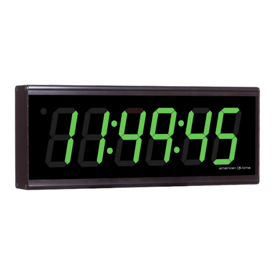
Summary of Contents for American Time SiteSynq IQ
- Page 1 Installation and Operation Manual Wireless Digital Clocks with Optional Calendar and Elapsed Time Indicator/Code Blue Part # H005112 Rev. 1 January 2020...
- Page 2 Electrical Shock Hazard Wireless Digital Clocks Owner's Manual WARNING: Hazardous voltage in electrical equipment can cause severe personal injury or death. Inspection, installation, and preventive maintenance should only be performed on equipment to which power has been turned off, disconnected and electrically isolated so no accidental contact can be made with energized parts. Electrostatic Sensitive Devices CAUTION: This equipment contains electronic devices that are sensitive to static electric charges.
-
Page 3: Table Of Contents
Appendix A: Timer Control Station Installation ....................17 Appendix B: Timer Control Station Installation Switch Functions ..............18 Appendix B: Timer Control Station Operators Flowchart .................. 19 American Time 140 3rd Street South PO Box 707 Dassel, MN 55325-0707 Phone: 800-328-8996 800-789-1882 Fax: american-time.com © American Time... -
Page 4: Important Installation And Warranty Information
IMPORTANT INSTALLATION AND WARRANTY INFORMATION WARRANTY INFORMATION: American Time (the Manufacturer) provides a limited warranty to the Original Purchaser of this product. The Original Purchaser is the party to whom the Manufacturer issued its Sales Order, generally the Manufacturer’s distributor. In order to preserve this warranty, it is important that only persons who have been properly trained and authorized by the Manufacturer service the product. -
Page 5: Specifications
Indications: ........Digital Clock/Timer hours and minutes – 4" and 2.5", bright red or green, seven segment LED’s hours and minutes are separated by a colon seconds ........ATSTCS Control Station – 2 second audible alarm Reception: ........Colons flash © American Time © American Time... -
Page 6: Description
• Optional Calendar Mode with configurable date/time display durations and six date display options: MM:DD:YY DD:MM:YY YY:MM:DD M:D:YY D:M:YY YY:M:D Digital Clock/Timer " " " 3/16 " display: 4- & 6-digit Control Station ATSTCS Control Station (optional) 4 9/16” CLOCK DOWN START/STOP RESET INCREMENT ENTER © American Time © American Time... -
Page 7: Installation Instructions
3. Mount the clock to the ceiling (4" box) or wall (single or double gang box). 4. Remove plastic protector from display face. 5. Apply power to the circuit and confirm correct operation. Ceiling mount 5" Wall mount " " 4", 6-digit shown © American Time © American Time... -
Page 8: Digital Clock Operation
Set the SET/RUN switch back to the RUN position. n Note: A preset of 00:00:00 allows the digital clock/timer to be used as a standard elapsed timer with a maximum elapsed time of 30:59:59. © American Time © American Time... -
Page 9: Timer Control Station Operation
When the timer reaches 00:00:00, the timer will stop counting and the audible alarm will sound for 2 seconds. During a DOWN count elapsed time operation, you can display any of the other time functions using the UP/DOWN/ CLOCK switch as desired © American Time © American Time... -
Page 10: Button Flowchart
AUto Selection will be controlled by the Press + Button master clock. Press OK Button CANC Press + Button Scrolling CANCEL Press + Button Press OK Button AUTO Continue to Software on Following Page © American Time © American Time... - Page 11 Press + Button Press + Button DATE Press OK Button + Cycles Options Scrolling 1 through 6 DATE DISPLAY (see table) Press + Button CANC Scrolling CANCEL Diagnostics DIA6 Continue to Diagnostics on Following Page © American Time © American Time...
- Page 12 Press + Button Press OK Button EVEN 0808 Scrolling Displays SSIQ EVENt CAPCOdE Events Cap Code Press + Button When complete, Press OK Button B I6 CANC press [SET/RUN]. Scrolling Scrolling CANCEL B 16HtNEss © American Time © American Time...
-
Page 13: Calendar Display Options
"0," the clock will display only DAte DUrAT ION the time). There are six options for the calendar format: DATE DISPLAY Calendar format option number MM:DD:YY DD:MM:YY YY:MM:DD M:D:YY D:M:YY YY:M:D © American Time © American Time... -
Page 14: Code Blue
Blue occurs, that particular timer will be reset when the clock is reset back to normal operation. 12VAC/DC TO 30VAC/DC POWER ON NORMALLY-OPEN SWITCHED CIRCUIT SUPPLIED FROM CODE BLUE UNIT. CODE BLUE UNIT – RESET PIEZO ENTER BUZZER START/STOP INCREMENT © American Time © American Time... -
Page 15: Important Considerations
However, to assure the reliability of this product, it is recommended that the Digital Clock/Timer be tested at least every six (6) months with the Control Station and Code Blue contact for operation in accordance with wiring configurations used. © American Time © American Time... -
Page 16: Maintenance
An incompatible battery may leak or explode, causing equipment damage and/ or personal injury! If battery must be replaced, contact American Time at 800-328-8996. System Maintenance The Digital Clock/Timer and ATSTCS Control Station have been manufactured for years of dependable, reliable use. -
Page 17: Appendix A: Timer Control Station Installation
7. PIEZO – Violet Wire 8. GND – Black Wire 12VAC/DC TO 30VAC/DC POWER ON NORMALLY-OPEN SWITCHED CIRCUIT SUPPLIED FROM CODE BLUE UNIT. CODE BLUE UNIT – RESET PIEZO ENTER BUZZER START/STOP INCREMENT ATSTCS Wiring DIagram © American Time © American Time... -
Page 18: Appendix B: Timer Control Station Installation Switch Functions
Run/Set Switch is in Run position. • This button can also be used to select a field (i.e. format, minute digits, hour digits) when the Run/Set Switch is in Set position. ENTER CLOCK DOWN START/STOP RESET INCREMENT ENTER © American Time © American Time... -
Page 19: Appendix B: Timer Control Station Operators Flowchart
Press RESET to reset counter To Reset Clock/Timer to Normal Operation Place SET/RUN switch momentarily in SET position and return switch to RUN position CLOCK DOWN START/STOP RESET INCREMENT ENTER " display: 4- & 6-digit © American Time © American Time...


Need help?
Do you have a question about the SiteSynq IQ and is the answer not in the manual?
Questions and answers