Table of Contents

Related Manuals for Inline IN1124


Summary of Contents for Inline IN1124
- Page 1 IN 1 1 24 / IN1 130 TWISTED PAIR TRANSMITTER / 1X4 DISTRIBUTION AMPLIFIER FOR HIGH RESOLUTION VIDEO & AUDIO TWISTED PAIR RECEIVER / 1X2 DISTRIBUTION AMPLIFIER FOR HIGH RESOLUTION VIDEO & AUDIO IN 1 1 24/IN 1 1 30 OPERATION MANUAL...
-
Page 2: Fcc Compliance
Installation and Safety Instructions For Models without a Power Switch: The socket outlet shall be installed near the equipment and shall be accessible. For all Models: No serviceable parts inside the unit. Refer service to a qualified technician. For Models with Internal or External Fuses: For continued protection against fire hazard, replace only with same type and rating of fuse. -
Page 3: Product Overview
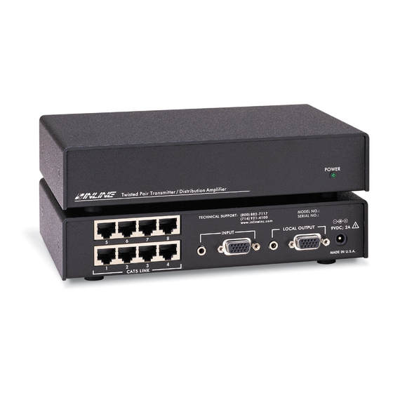
IN1124-2 Twisted Pair Transmitter / Distribution Amplifier for High-Resolution Video & Audio - provides the same features as the IN1124-1 as well as dual stereo mini connectors: one for stereo audio input, and the other to drive a local audio device. - Page 4 Using special technology that allows high resolution video and stereo audio transmission over CAT 5 cables, the IN1124 / IN1130 system leverages the many advantages of CAT5 cable and provides A/V systems designers with an economical, space efficient solution for high-resolution video and audio signal transmission in a variety of applications.
-
Page 5: Installation
1.) Place / install the IN1124 at the desired location. Make sure that the unit is seated on a flat surface or is securely installed in a standard 19” equipment rack using an optional IN9080 rack shelf. - Page 6 11.) Connect the round connector on the IN9211-1 / IN9211-5 power supply (included) to the power input jack of the IN1124 (also located on the right side of the rear panel). Connect the adapter box side of the power supply to the A/C power source.
- Page 7 SUGGESTED MAXIMUM CABLE LENGTHS Several factors will affect the video signal quality you can expect using the IN1124 / IN1130 system including the input signal resolution and refresh rate, quality of CAT5 cable and the length of cable. Generally speaking, the higher the signal bandwidth, the shorter the distance it can be transmitted along any cable (coaxial or UTP) before it begins to degrade.
- Page 8 ADAPTER / EXTENSION CABLES FOR INPUT AND LOCAL MONITOR / DISPLAY DEVICE OUTPUT The IN1124 / IN1130 system has 15-pin HD VGA-type input / output connectors. The following adapter / extension cables are available: Computer VGA: 15-Pin HD Input Cable...
-
Page 10: Specifications
Dimensions Regulatory Approvals Parts Included IN1124-1 - Twisted Pair Transmitter / Distribution Amplifier for High-Resolution Video, or IN1124-2 - Twisted Pair Transmitter / Distribution Amplifier for High-Resolution Video & Audio IN9211-1 - 9VDC, 2.0A External Adapter - U.S. Style / 120VAC, or IN9211-5 - 9VDC, 2.0A External Adapter - Continental Style / 230VAC... -
Page 11: Troubleshooting
IN9089: “L” Brackets Troubleshooting Problem: The IN1124 / IN1130 is plugged in but the power indicator light / front panel LED is dark. Solution 1: Make sure that the power adapter is securely plugged into the unit and the A/C source. -
Page 12: Warranty
The technical information contained herein regarding the IN1124 / IN1130 features and specifications is subject to change without notice.
Need help?
Do you have a question about the IN1124 and is the answer not in the manual?
Questions and answers