
Related Manuals for Inline IN3212


Summary of Contents for Inline IN3212
-
Page 1: Operation Manual
Operation Manual High Resolution Video Distribution Amplifier / Line Driver Series: IN3212 - 1-In, 2-Out Distribution Amplifier IN3214 - 1-In, 4-Out Distribution Amplifier IN3218 - 1-In, 8-Out Distribution Amplifier... -
Page 2: Installation And Safety Instructions
Installation and Safety Instructions For Models without a Power Switch: The socket outlet shall be installed near the equipment and shall be accessible. For Models with 110 / 220V Power Selector: Caution: Before applying power to this unit, the voltage selector must be set to the appropriate setting to match local A/C line voltage. - Page 3 Installations und Sicherheitshinweise Für Geräte ohne Netzschalter: Die Netzsteckdose soll in de Nähe des Gerätes installiert und frei zugänglich sein. Für Geräte mit 110 / 220V Spannungswähler: Achtung: Bevor Sie dem Gerät Spann ung zuführen, muß der Spannungswähler entsprechend der Spannung des lokalen Wechselspannungsnetzes eingestellt werden.
-
Page 4: Fcc Compliance
CE COMPLIANCE All products exported to Europe by Inline, Inc. after January 1, 1997 have been tested and found to comply with EU Council Directive 89/336/EEC. These devices conform to the following standards: EN50081-1 (1991), EN55022 (1987) EN50082-1 (1992 and 1994), EN60950-92... -
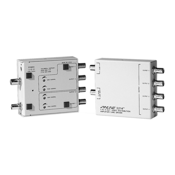
Page 5: Product Features
The IN3212, IN3214 and IN3218 are high performance video distribution amplifiers with gain and peaking controls. • The IN3212 is a 1 in 2 out composite video distribution amplifier / line driver. • The IN3214 is a 1 in 4 out video distribution amplifier / line driver. -
Page 6: Installation
INTERNAL CONTROLS section on page 3 and set jumper as appropriate. 2. Connect the video signal from the source to the IN3212 / IN3214 / IN3218 input. 3. Connect the output(s) to the display device(s) or other equipment. -
Page 7: Gain Control
INTERNAL CONTROLS CAUTION: Adjustment of the IN3212 / IN3214 / IN3218 internal controls must only be carried out by qualified technicians. Care must be taken to avoid static shock to the internal components. The IN3212 / IN3214 / IN3218 have internal jumpers which can be accessed using the following procedure: 1. -
Page 8: Jumper Functions
(Loop Through Not Used) Input is Unterminated (High Z) Open Closed Closed (Loop Through Connected to a Local Monitor or Another Amplifier ) *Factory Default Settings IN3212 / IN3214 / IN3218 OPERATION MANUAL - REV. 1 10/25/97 ©1997 - INLINE, INC. - Page 9 Split Mode - Unit Operates as Two Open Open Open Open Independent 1 x 2 Distribution Amplifiers Input 1 & Input 2 Unterminated (High Z) *Factory Default Settings © 1997 - INLINE, INC. IN3212 / IN3214 / IN3218 OPERATION MANUAL - REV. 1 10/25/97...
- Page 10 Split Mode - Unit Operates as Two Independent Open Open Open Open 1 x 2 Distribution Amplifiers Input 1 & Input 2 Unterminated (High Z) *Factory Default Settings IN3212 / IN3214 / IN3218 OPERATION MANUAL - REV. 1 10/25/97 ©1997 - INLINE, INC.
-
Page 11: Specifications
IN9204 9 VDC 500 mA Power Supply IN9333 Gain / Peaking Adjustment Tool Operation Manual Optional Accessories IN9127 (for IN3214/IN3218); IN9128 (for IN3218). Mounting Brackets © 1997 - INLINE, INC. IN3212 / IN3214 / IN3218 OPERATION MANUAL - REV. 1 10/25/97... -
Page 12: Troubleshooting
TROUBLESHOOTING Problem: There is no image on the output of the IN3212 / IN3214 / IN3218. Suggestions: Make sure the power supply is plugged in and that the input and output cables are connected properly. Bypass the IN3212 / IN3214 / IN3218 by connecting the input and output cables with a BNC barrel connector to ensure there is a video signal present. -
Page 13: Warranty
The information in this manual has been carefully checked and is believed to be accurate. However, Inline, Inc. assumes no responsibility for any inaccuracies that may be contained in this manual. In no event will Inline, Inc. be liable for direct, indirect, special, incidental, or consequential damages resulting from any defect or omission in this manual, even if advised of the possibility of such damages.
Need help?
Do you have a question about the IN3212 and is the answer not in the manual?
Questions and answers