Broseley York Midi Installation & Operating Instructions Manual
Conventionally flued natural gas stove
Hide thumbs
Also See for York Midi:
- Operation manual (19 pages) ,
- Installation and operation manual (19 pages) ,
- Installation manual (12 pages)
Table of Contents
Advertisement
Quick Links
Installation & Operating Instructions
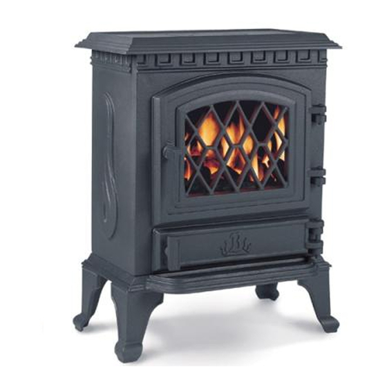
Model: York Midi
Conventionally Flued Natural Gas Stove
PLEASE LEAVE THESE INSTRUCTIONS WITH THE USER
Broseley Fires do not provide flue pipes, closure plates or any other
associated accessory.
Please note gas installations MUST only be carried out by installers who
are Gas Safe registered.
200708_3
Advertisement
Table of Contents

Subscribe to Our Youtube Channel
Related Manuals for Broseley York Midi


Summary of Contents for Broseley York Midi
- Page 1 Model: York Midi Conventionally Flued Natural Gas Stove PLEASE LEAVE THESE INSTRUCTIONS WITH THE USER Broseley Fires do not provide flue pipes, closure plates or any other associated accessory. Please note gas installations MUST only be carried out by installers who are Gas Safe registered.
-
Page 2: Table Of Contents
Contents Introduction Packing List Specification Dimensions Hearth Requirements Chimney Requirements Assembly Burner Installation Gas Connection & Pressure Testing Positioning the Coal Ceramics Spillage Testing Operating the Stove The Remote Control Curing the Paint & Warning Notes Trouble-shooting Servicing Instructions Commissioning Form Annual Service Record Guarantee 200707_3... -
Page 3: Introduction
Introduction THANK YOU FOR PURCHASING A GAS FIRED STOVE Broseley Fires Ltd, a family run company, was founded as an appliance and design development company in 1975. Since then we have built up an enviable reputation for the quality, reliability and fuel efficiency of our stoves. -
Page 4: Specification
Specification Heat Input (Gross) 6.2 kW Max Heat Ouput 4.6 kW Gas Category Supply Pressure 20 mbar Gas Rate 0.59 m Injector Size Spigot diameter 125mm (5”) Weight 65 Kg Country of destination GB, IE Efficiency Class 1 Please note this product is designed to only use natural gas. Dimensions All dimensions are in millimetres 200707_3... -
Page 5: Hearth Requirements
Hearth Requirements The appliance needs to be located onto a solid non-combustible hearth with a minimum thickness of 12mm. The hearth must be capable of withstanding the weight of the appliance. To ensure correct combustion the following minimum clearances must be adhered to: Inglenook Installation Freestanding Installation... -
Page 6: Chimney Requirements
Chimney Requirements Please note Broseley Fires do not provide flue pipes, closure plates or any other associated accessory. The stove must be installed in accordance with current gas and buildings regulations BS5871: Part1. The appliance can be installed in any adequate area suitable for solid fuel fires and stoves. -
Page 7: Assembly - Burner Installation
Assembly - Burner Installation Ensure all components are present prior to commencing assembly (See Packing List on page 3). 1. Unscrew the M6 x 18 Hex Bolt and open the main stove door to retrieve the box containing the 4 Legs, Handle and Allen Key. Using the bolts located in the bottom of the stove affix the Legs. -
Page 8: Gas Connection & Pressure Testing
Replacement ceramics are available from your dealer. Whilst arranging the ceramics, ensure that the pilot is not obstructed. Broseley Fires Ltd accepts no responsibility for any injury sustained whilst handling hot ceramics. Before any ceramics are placed in position ensure that the burner is operating correctly. - Page 9 Assembly – Positioning the Coal Ceramics Warning: Ceramic coals are very fragile so always handle with care when fitting them. Follow these instructions carefully. Ceramics that are positioned wrongly could seriously alter the performance of your appliance. Stage 1 Stage 3 Place largest coal matrix firmly against the Place the final coal matrix on top of the back of the stove with the three arches to...
-
Page 10: Spillage Testing
Spillage Testing A Spillage Test MUST be made before the installed fire is left with the customer. Carry out the test by first closing all doors and windows in the room containing the fire. Insure that the fire is burning at full rate for a minimum of 10-15 minutes. Using a lighted smoke match run it along the top edge of the draught diverter on the rear of the stove, observing the smoke being drawn into the dilution box, after 10 minutes repeat the test... - Page 11 Operating the Stove It is important to read these instructions thoroughly before lighting the stove. The gas stove operates with a traditional permanent pilot light. The knobs for ignition and power control are located on the lower right hand side of the stove.
-
Page 12: Operating The Stove The Remote Control
Operating the Stove – The Remote Control POSITIONING THE RECEIVER After fitting the batteries in the receiver and the hand set, place the receiver anywhere on the hearth. There is a long lead on the receiver to allow you to position the receiver towards the front of the hearth, if you wish to see the light come on when the handset is in use. - Page 13 Operating the Stove – The Remote Control Transmitter Function Set the Display After connecting the battery or by simultaneously pressing AUTO and TIMER, the display flashes. You are in set mode. From set mode, press AUTO to switch from °F (and 12 hour clock) to °C (and 24 hour clock) or vice versa.
- Page 14 Operating the Stove – The Remote Control Timer Mode (TIMER in display) • During heating periods P1* and P2*, the temperature is controlled in the same manner as in automatic mode. When the timer program turns to w (heating cycle off), the motor will turn the valve to pilot and there is no temperature control.
-
Page 15: Curing The Paint & Warning Notes
Curing the Paint It is important to note that upon initial lighting of the stove you will notice a strong odour, this is the paint curing and is completely normal. Most high temperature paints operate in the same way. They use a resin which dries at room temperature and a silicon resin which cures at high temperatures. -
Page 16: Trouble-Shooting
Trouble-shooting THE GAS PILOT WILL NOT IGNITE OR STAY LIT • Ensure the gas is turned on at the appliance and the meter / cylinder. • Hold the pilot gas button for at lest 20 seconds once the pilot is alight to ensure the operation of the safety thermocouple valve. -
Page 17: Servicing Instructions
Servicing Instructions Servicing should be carried out annually by a qualified installation engineer when the stove is cold and the gas supply is turned off at the isolation tap. The following points should be checked. • Remove the coals and clean any dust and debris from the top of the burner unit. -
Page 18: Commissioning Form
Commissioning Form THIS SECTION MUST BE COMPLETED AND SIGNED BY THE INSTALLATION ENGINEER PLEASE LEAVE WITH THE CUSTOMER AND THE APPLIANCE. Size of Governor setting: (i.e.) Natural Gas 20MBAR Length and size of gas supply: _______________ Meter pressure Fire only on: ________________ All Other appliances on: __________________ Burner pressure Fire only on: _______________ All Other appliances on: __________________... -
Page 19: Annual Service Record
Annual Service Record 1ST YEAR SERVICE completion date: SERVICE ENGINEER: REG. No. COMPANY NAME: COMPANY ADDRESS: POSTCODE: CONTACT NUMBER 2ND YEAR SERVICE completion date: SERVICE ENGINEER: REG. No. COMPANY NAME: COMPANY ADDRESS: POSTCODE: 3RD YEAR SERVICE completion date: SERVICE ENGINEER: REG. -
Page 20: Guarantee
The rights given in this guarantee are limited to the UK mainland and are in addition to any to which you may have a statutory entitlement. Please retain your purchase receipt. We will need to see this in the event of a claim under warranty. Broseley Fires Ltd Knights Way Battlefield Enterprise Park Shrewsbury...
Need help?
Do you have a question about the York Midi and is the answer not in the manual?
Questions and answers