
Related Manuals for Marshall Electronics V-LCD651STX-HDA


Summary of Contents for Marshall Electronics V-LCD651STX-HDA
-
Page 1: Operating Instructions
Marshall Electronics V-LCD651STX-HDA Model No. V-LCD651STX-HDI Model No. V-LCD651STX-3GSDI Model No. 6.5” High Resolution Super Transflective Field Monitor Operating Instructions... -
Page 3: Table Of Contents
Product Overview.................................. 4 Features ....................................4 Installation and Initial Setup ..............................5 Front and Side Monitor Features............................6 Rear Monitor Features ................................7 Compatible Input Formats..............................8 On Screen Menu ..................................9 MAIN MENU AND NAVIGATION ............................10 VIDEO CONFIGURATION SUBMENU ..........................10 MARKER CONFIGURATION SUBMENU ........................ -
Page 4: Product Overview
You also have the option of creating ■ Super Transflective your own screen markers with the User option. The V-LCD651STX-HDA can be used in locations ■ User-Definable Function Buttons with high intensity ambient light. This monitor performs very well in sunlight, or indoors under direct Four user-definable function buttons on the front- studio lighting. -
Page 5: Installation And Initial Setup
Inspect the unit for any physical damage that may have occurred during shipping. Should there be any damage, immediately call Marshall Electronics Customer Service at (800) 800-6608. If you are not located within the continental United States, call +1 (310) 333-0606. -
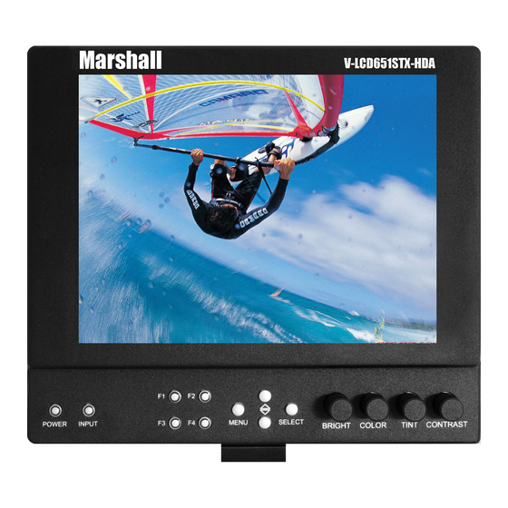
Page 6: Front And Side Monitor Features
Front and Side Monitor Features Image Adjustment Knobs Power Button Use the image adjustment knobs to adjust Use the power button to toggle between ON and brightness, color saturation, and contrast of the STANDBY modes. In the STANDBY state, the LED image. -
Page 7: Rear Monitor Features
Power can be supplied from the included Module Slot power supply, or from a variety of DC sources This area is intended for the Marshall Electronics supplying at least 1 Amp at 12 Volts. modules, which are factory installed. -
Page 8: Compatible Input Formats
Compatible Input Formats The following standards are supported by the V-LCD651STX monitors: Composite (CVBS) NTSC, PAL Component (YPbPr) 480i60, 576i50 720p (30, 29.97, 25) 720p ( 60 / 59.94 / 50) 1080p (30, 29.97, 25, 24, 24 sF, 23.98, 23.98 sF) 1080i (60 / 59.94 / 50) , HDMI and 3GSDI Inputs V-LCD651STX-3GSDI –... -
Page 9: On Screen Menu
On Screen Menu RGB Bias and Gain R, G, B Bias (0-100) / R, G, B Gain (0-100) Check Field Off, Mono, Blue, Green, Red Ratio 4:3, 16:9 Video Configuration Pixel-to-Pixel Off, Centered, User H/V Delay * Off, H & V Delay, V Delay, H Delay Underscan * Off, On NTSC Black Level **... -
Page 10: Main Menu And Navigation
MAIN MENU AND NAVIGATION Main Menu Access the main menu by pushing and holding the MENU button on the front panel of the monitor. •Step through menu items using the ▲ and ▼ buttons. •Choose a submenu or select a menu item by pressing SELECT. •Return to the previous menu by pressing MENU. -
Page 11: Check Field
Disable Blue Check Field mode. ■ Aspect Ratio Settings Use to switch between 4:3 and 16:9 aspect ratios. As the V-LCD651STX-HDA monitor has a native resolution of 1024 x 768 RGB pixels, incoming images are automatically scaled to fit the screen: •... - Page 12 Note: The aspect ratio setting is ignored when Pixel-to-Pixel mode is enabled. ■ Pixel-to-Pixel Mode Use this setting to enable Pixel-to-Pixel mode. You have the option of viewing the center 1024 x 768 (Centered Pixel- to-Pixel mode) or selecting any 1024 x 768 area on the screen (User Pixel-to-Pixel mode). The User Pixel-to-Pixel option is not available when the incoming image is 1024 x 768 or lower - only the Centered Pixel-to-Pixel mode can be used in this case.
-
Page 13: Ntsc Black Level
■ H/V Delay Use this setting to enable one of three delay modes (H & V Delay, V Delay, H Delay): • In H & V Delay mode, both horizontal sync and vertical sync are delayed, resulting in both horizontal and vertical blanking periods being shown on the screen. -
Page 14: Marker Configuration Submenu
MARKER CONFIGURATION SUBMENU Marker Configuration Submenu ■ Markers Use this setting to enable or disable all on-screen markers. This setting affects the center marker, full screen markers, 16:9 markers and 4:3 markers. ■ Center Marker Use this setting to display a center marker on the screen. ■... -
Page 15: User Markers
■ 4:3 Markers Use this setting to superimpose one of 5 markers on the screen when in 4:3 mode. This setting is disabled when the aspect ratio is set to 16:9, or when Pixel-to-Pixel, Underscan, or H/V Delay is enabled. •... -
Page 16: Marker Background
■ Marker Background Use this setting to choose how selected markers are displayed on the screen. : • 0% The marker is superimposed on the complete image. • 25% Image area beyond the marker is shown at 25% intensity. • 50% Image area beyond the marker is shown at 50% intensity. -
Page 17: Filter Configuration Submenu
FILTER CONFIGURATION SUBMENU ■ False Colors The V-LCD651STX has a false color filter to aid in the setting of camera exposure. As the camera Iris is adjusted, elements of the image will change color based on the luminance or brightness values. This enables proper exposure to be achieved without the use of costly, complicated external equipment. -
Page 18: System Configuration Submenu
■ Splash Screen Use this option to enable or disable the Marshall Electronics Inc. splash screen seen when the monitor is first powered ■ Freeze Input Use the Freeze function to “freeze” the current image on the screen. Select this menu item again (Unfreeze) to return to the real-time video input. -
Page 19: Function Presets Submenu
Mosquito Filter • Peaking Filter • False Colors • Freeze Input • Aspect Markers • Center Marker • Markers • Underscan • H/V Delay • Pixel-to-Pixel • Level Sensor: Requires the Level Sensor accessory. Contact Marshall Electronics for more information. -
Page 20: System Information Submenu
SYSTEM INFORMATION SUBMENU ■ System This shows the System firmware version of your monitor. ■ Keypad This shows the Keypad firmware version of your monitor. ■ Module This shows your module version (HDMI or 3GSDI) and the firmware version of your module. -
Page 21: Specifications
Specifications ■ ELECTRICAL ■ PANEL Screen Size 6.5” Diagonal Power Consumption 1.25 Amp (Max) @ 12VDC (16W Max) Display Area (h x v) 132.10 x 99.07 mm Voltage Requirement 12VDC (7VDC-20VDC) Aspect Ratio 4:3 (16:9 / 4:3 Selectable) V-PS12-5V-XLR Power Supply: Pixels 1024 x 768 Input... -
Page 22: Dimensions
Dimensions... -
Page 23: Maintenance
This warranty is extended to the first consumer only, and proof of purchase is necessary to honor the warranty. If there is no proof of purchase provided with a warranty claim, Marshall Electronics reserves the right not to honor the warranty set forth above. - Page 24 2010-0512 Marshall Electronics, Inc. 1910 East Maple Ave. El Segundo, CA 90245 Tel: (800) 800-6608 / (310) 333-0606 • Fax: 310-333-0688 www.LCDRacks.com • sales@lcdracks.com...
Need help?
Do you have a question about the V-LCD651STX-HDA and is the answer not in the manual?
Questions and answers