Table of Contents
Advertisement
Quick Links
Advertisement
Table of Contents

Related Manuals for Fujitsu Siemens Computers SCENIC E


Summary of Contents for Fujitsu Siemens Computers SCENIC E
- Page 1 Professional PC English Operating Manual SCENIC E...
- Page 2 ... any technical problems or other questions which you would like to be clarified? Please contact: ● your sales partner ● your sales outlet Further information can be found in the "Safety", "Ergonomics" and "Warranty" manuals. The latest information on our products, tips, updates, etc., can be found on the internet under: http://www.fujitsu-siemens.com...
- Page 4 Questo manuale è stato stampato su carta da riciclaggio. Denna handbok är tryckt på recyclingpapper. Dit handboek werd op recycling-papier gedrukt. Published by Fujitsu Siemens Computers GmbH Order No.: A26361-K675-Z120-1-7619 Edition 3 Printed in the Federal Republic of Germany AG 0105...
-
Page 5: Operating Manual
Introduction Important notes SCENIC E Preparing for use Operation Troubleshooting and tips Operating Manual System expansions Technical data Index January 2005 edition... - Page 6 SCENIC is a registered trademark of Fujitsu Siemens Computers GmbH. Microsoft, MS, MS-DOS, Windows, and Windows NT are registered trademarks of Microsoft Corporation. VESA and DPMS are trademarks of Video Electronics Standards Association. PS/2 is a registered trademark of International Business Machines, Inc.
-
Page 7: Table Of Contents
Contents Your SCENIC E..........................1 Notational conventions ........................2 Important notes ..........................3 Safety notes ............................3 Energy saving, disposal and recycling ..................3 CE marking............................4 FCC Class B Compliance Statement....................5 Transporting the PC...........................5 Cleaning the PC ..........................5 Preparing for use..........................7 Unpacking and checking the delivery....................7 Steps for initial setup .........................7... - Page 8 Contents Troubleshooting and tips ......................27 Installing new software ........................27 Power-on indicator remains unlit after you have switched on your device ........27 The screen stays blank ........................28 No mouse pointer displayed on the screen ..................29 The floppy disk cannot be read or written ..................29 Time and/or date is not correct......................
-
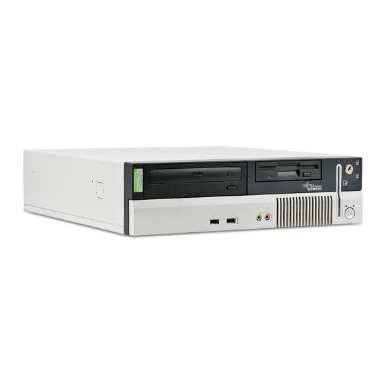
Page 9: Your Scenic E
Your SCENIC E..is available with various configuration levels with different hardware and software. In addition, you can install accessible drives (e.g. DVD drive), hard disks and other boards. This manual tells you how to put your PC into operation and how to operate it in daily use. This manual applies for all configuration levels. -
Page 10: Notational Conventions
Introduction Notational conventions The following symbols are used in this manual: indicates information which is important for your health or for preventing physical damage. indicates important information which is required to use the system properly. ► Text which follows this symbol describes activities that must be performed in the order shown. -
Page 11: Important Notes
Important notes In this chapter you will find information regarding safety which is essential to take note of when working with your PC. Safety notes Pay attention to the information provided in the "Safety" manual and in the following security notes. During installation and before operating the device, please observe the instructions on environmental conditions in the "Technical data"... -
Page 12: Ce Marking
You will find the Declaration of Conformity for this device as a PDF file in the "Wireless LAN" manual on the "User Documentation" CD or in the Internet under http://manuals.fujitsu-siemens.com. A26361-K675-Z120-1-7619, edition 3... -
Page 13: Fcc Class B Compliance Statement
● Consult the dealer or an experienced radio/TV technician for help. Fujitsu Siemens Computers GmbH is not responsible for any radio or television interference caused by unauthorised modifications of this equipment or the substitution or attachment of connecting cables and equipment other than those specified by Fujitsu Siemens Computers GmbH. The correction of interferences caused by such unauthorised modification, substitution or attachment will be the responsibility of the user. -
Page 15: Preparing For Use
Preparing for use Please take note of the safety information in the "Important notes" chapter. Unpacking and checking the delivery It is recommended not to throw away the original packaging material! It may be required for reshipment at some later date. ►... -
Page 16: Setting Up The Pc
Preparing for use Setting up the PC When installing your PC, give consideration to the recommendations and safety notes in the "Safety" manual. Set up the PC only in its correct orientation. The points to observe are illustrated on the following pages. - Page 17 Preparing for use Proceed as follows to prepare the PC for the vertical operating position: ► If you have already operated the PC, switch it off and disconnect all cables from the casing. ► Assemble the base feet in the direction of the arrow.
-
Page 18: Connect The Monitor, Mouse And Keyboard
Preparing for use Connect the monitor, mouse and keyboard The ports for the monitor, mouse, and keyboard are on the rear and front (USB ports) of the PC. Keyboard port / purple PS/2 mouse port / green USB port / black Monitor port / blue Connecting the monitor ►... -
Page 19: Connecting The Mouse
Preparing for use Connecting the mouse Depending on the equipment level selected, your PC will be supplied with a PS/2 mouse or a USB mouse. Connecting a PS/2 mouse ► Connect the PS/2 mouse to the PS/2 mouse port of the PC. Connecting USB mouse ►... -
Page 20: Connecting The Pc To The Mains Voltage
Preparing for use Connecting the PC to the mains voltage ► Connect the power cable to the PC (1). ► Plug the power plug into a grounded mains outlet (2). A26361-K675-Z120-1-7619, edition 3... -
Page 21: Initial Switch-On: Software Will Be Installed
Preparing for use Initial switch-on: Software will be installed If the PC is connected to a network, the network protocol is required as well as the user and server details. Contact your network administrator if you have any questions about these settings. When you switch on your PC for the first time, the supplied software is installed and configured. -
Page 22: Switching On Monitor And Pc
Preparing for use Switching on monitor and PC ► Switch the monitor on (see the operating manual for the monitor). ► Switch the PC on. To do this, follow the instructions below. 1 = Main switch 0 = PC is switched off 2 = ON/OFF switch I = PC is ready-to-operate ►... -
Page 23: Installing The Software
Preparing for use Installing the software ► During installation, follow the instructions on screen. Consult the operating system manual if there is anything unclear about the requested input data. You will find further information about the system, drivers, utilities, updates, manuals etc. on the "Drivers &... -
Page 24: Ports On The Pc
Preparing for use Ports on the PC The ports for external devices are on the rear and on the front of the PC. The ports available on your PC depend on the configuration level you have selected. The standard ports are marked with the symbols shown below (or similar). -
Page 25: Connecting External Devices To The Parallel Port
Preparing for use Connecting external devices to the parallel port External devices can be connected to the parallel port (e.g. a printer). ► Connect the data cable to the external device. ► Connect the data cable to the parallel port For an exact description of how to connect external devices to the parallel port, please see the device documentation. -
Page 27: Operation
Operation Switching on the PC ► If necessary, switch the monitor on (see the operating manual for the monitor). ► Switch the PC on with the main power switch on the rear of the PC. ► Press the ON/OFF switch on the front of the PC. The power-on indicator lights green and the PC is started. -
Page 28: Indicators On The Pc
Operation Indicators on the PC The indicators are on the front of the PC. Which indicators are available on your PC depends on the configuration level you have selected. 1 = CD-ROM indicator 4 = Power-on indicator 2 = Floppy disk indicator 5 = Hard disk indicator 3 = SmartCard reader indicator 1 - CD-ROM indicator... -
Page 29: Keyboard
Operation 4 - Power-on indicator – The indicator lights green: The PC is on. The display can also light up green if the PC has been switched off by holding the ON/OFF switch (see the "Tips" section). – The indicator lights orange: The PC is in energy-saving mode. -
Page 30: Important Keys And Key Combinations
Operation Important keys and key combinations The following description of keys and key combinations refers to MS Windows. Details of other keys and key combinations can be found in the documentation of the relevant application programme. ON/OFF switch (optional) Depending on the setting in the BIOS Setup, the system can be switched on, off, or on and off with this button. -
Page 31: Working With Floppy Disks
Operation Working with floppy disks Follow the instructions supplied by the vendor of the floppy disks. Never clean the floppy disk drives with cleaning disks. Any attempt would destroy the read/write head in the disk drive within 20 seconds. 1 = Insertion direction 2 = Label area 3 = Write protection tab for a 1.44 Mbyte floppy disk 4 = Identification of a 1.44 MB floppy disk or write protect switch on a 120 MB floppy disk... -
Page 32: Settings In Bios Setup
Operation Settings in BIOS Setup The BIOS Setup menu allows you to set your hardware configuration and system functions. When the PC is delivered, the default entries are valid (see "BIOS Setup" manual and if necessary technical manual for the mainboard). You may customise these settings to your requirements in the BIOS Setup. -
Page 33: Anti-Theft Protection And Lead-Sealing
Operation Anti-theft protection and lead-sealing There are three ways to protect your PC from theft: ● with the Kensington Lock device (1) and with a Kensington MicroSaver ● with a chain (lead-seal) ● with a (pad)lock To prevent unauthorised persons from opening the casing, the casing can be sealed. To do this, feed the sealing chain through the eye (2) and seal the chain with the lead seal. -
Page 34: Access Authorisation Via Smartcard
Operation Access authorisation via SmartCard In systems equipped with a SmartCard reader, access can be restricted to those users who have a corresponding SmartCard. Access protection with SystemLock With SystemLock you can protect your system from unauthorised booting. Then a system can only be booted when the user inserts a valid SmartCard in the SmartCard reader and enters his/her personal code number (PIN). -
Page 35: Troubleshooting And Tips
Troubleshooting and tips Take note of the safety notes in the "Safety" manual and in the "Preparing for use" chapter, when you connect or disconnect cables. If a fault occurs, try to correct it as described in the following places: ●... -
Page 36: The Screen Stays Blank
Troubleshooting and tips The screen stays blank If your screen remains blank this may be due to the following: Monitor is switched off ► Switch your monitor on. Power saving has been activated (screen is blank) ► Press any key on the keyboard. ►... -
Page 37: No Mouse Pointer Displayed On The Screen
Troubleshooting and tips Wrong monitor has been set under Window XP ► Restart the PC. ► Press F8 while the system is booting. Either the Windows Advanced Start Options menu or the menu for selecting the operating system appears. ► If the menu for selecting the operating system appears, press F8 . -
Page 38: Time And/Or Date Is Not Correct
Troubleshooting and tips Time and/or date is not correct You can set the time and date in the BIOS Setup or in the operating system. ► Set the time and date. If the time and date are repeatedly wrong when you switch on your PC, the on-board battery is flat. -
Page 39: System Expansions
System expansions As the PC has to be shut down in order to install/deinstall system hardware components, it is a good idea to print out the relevant sections of this chapter. It may be necessary to update the BIOS when carrying out a system expansion or hardware upgrade. -
Page 40: Opening The Casing
System expansions Opening the casing ► Switch the PC off. The PC must not be in the energy-saving mode! Please take note of the safety information in the "Important notes" chapter. Pull the power plug out of the mains outlet! ►... -
Page 41: Closing The Casing
System expansions Closing the casing ► Place the top cover on the casing base (1) so that the distance (a) is approximately 2 cm. Ensure that the top cover of the casing engages in the guide rails in the lower part of the casing. -
Page 42: Installing And Removing A Board
System expansions Installing and removing a board Please take note of the section "Information about boards". Removing board bracket ► Open the casing (see "Opening the casing"). ► Pull the board bracket out of the casing in the direction of the arrow. Installing board bracket ►... -
Page 43: Installing A Board
System expansions Installing a board ► Make the required settings for the board. Do not dispose of the slot cover. For cooling, protection against fire and in order to comply with EMC regulations, you must refit the slot cover if you remove the board. ►... - Page 44 System expansions ► Push the board up to its slot in the direction of the arrow as far as the stop. ► Press the board into the slot so that it engages. ► Fold up the retaining bracket so that it engages.
-
Page 45: Removing A Board
System expansions Removing a board ► Disconnect the cables connected to the board. ► Press on the retaining bracket in the direction of the arrow and fold it down. ► Pull the board out of the slot of the board bracket in the direction of the arrow. - Page 46 System expansions ► Push the slot cover into the slot in the direction of the arrow. Ensure that the point of the slot cover engages on the outside of the board bracket. ► Fold up the retaining bracket so that it engages.
-
Page 47: Low-Profile Boards
System expansions Low-Profile boards For units with a particularly low overall height, there are so-called low-profile boards with a slot cover with a lower overall height to match the low-profile units. To also install these low-profile boards in normal board slots, you must mount a corresponding slot adapter beforehand The slot adapter is located on the slot cover of the upper slot. -
Page 48: Installing And Removing The Graphiks Card
System expansions Installing and removing the graphiks card Your device has a special slot for graphics cards (e.g. PCI Express Low Profile). Installing the graphics card ► Open the casing (see "Opening the casing" chapter). ► Remove the board bracket as described in "Removing board bracket" section. ►... - Page 49 System expansions ► Press the board into the slot so that it engages. ► Fold the retaining bracket down again in the direction of the arrow (2). Ensure that the retaining bracket engages. ► Install the board bracket as described in "Installing board bracket" section. ►...
- Page 50 System expansions ► Push the slot cover into the slot in the direction of the arrow (1). Make sure that the tip of the slot cover engages in the notch in the casing bottom. ► Fold the retaining bracket down again in the direction of the arrow (2). Ensure that the retaining bracket engages.
-
Page 51: Installing And Removing Drives
System expansions Installing and removing drives In the standard model the PC may be equipped with the following drives: ● one accessible 3 ½ inch drive (floppy drive) ● one non-accessible 3 1/2 inch drive (hard disk) ● one accessible 5 ¼ inch drive (e.g. DVD or CD ROM drive) ●... -
Page 52: Replacing Drive In 5 ¼ Inch Bay
System expansions Replacing drive in 5 ¼ inch bay ► Open the casing (see "Opening the casing" chapter). Removing a drive ► Pull the data and the power supply connectors from the desired drive. ► Press the EasyChange rails (1) together and pull the drive out of the casing (2). ►... - Page 53 System expansions Installing a drive ► Take the new drive out of its packaging. ► Adjust the required settings on the drive (if necessary, on already-installed drives as well). ► Press the EasyChange rails into the provided holes. ► Push the accessible drive into the casing (1) until the EasyChange rails engage. ►...
-
Page 54: Folding Up And Down The Drive Cage
System expansions Folding up and down the drive cage ► Open the casing (see "Opening the casing"). Please also observe the sticker on the drive cage. Folding up the drive cage ► Press on the drive cage lever (1). ► Fold the drive cage completely upward in the direction of the arrow (2). -
Page 55: Replacing The Floppy Disk Drive
System expansions Replacing the floppy disk drive ► Open the casing (see "Opening the casing" chapter). ► Fold up the drive cage (see "Folding up and down the drive cage" chapter). Removing the floppy disk drive ► Remove the screw (1). ►... - Page 56 System expansions Installing the floppy disk drive ► Slide the drive cage into the casing. ► Fold up the drive cage (see "Folding up and down the drive cage" chapter). ► Fasten the floppy disk drive with the screws (1). ►...
-
Page 57: Replacing A Hard Disk Drive
System expansions Replacing a hard disk drive ► Open the casing (see "Opening the casing" chapter). ► Fold up the drive cage (see "Folding up and down the drive cage" chapter). Removing a hard disk drive ► Disconnect all cables connected to the drive (data cable, power supply cable). ►... - Page 58 System expansions Installing a hard disk drive ► Take the new hard disk drive out of its packaging. ► Make the required settings on the drive if necessary (e.g. Master/Slave/CableSelect with IDE drives). ► Secure the EasyChange rails on the side of the hard disk by inserting the upper pins of the EasyChange rail in the corresponding holes of the hard disk.
-
Page 59: Replacing Second Hard Disk In 5 ¼ Inch Drive Carrier
System expansions ► Fold down the drive cage (see chapter "Folding up and down the drive cage"). ► Close the casing (see "Closing the casing" chapter). It may be necessary to modify the entry for the drive in the BIOS Setup. Replacing second hard disk in 5 ¼... - Page 60 System expansions Installing the hard disk ► Remove the new hard disk from the package. ► Slide the hard disk into the drive carrier in the direction of the arrow (1). ► Secure the hard disk with the screws (2). ►...
-
Page 61: Installing And Removing A Wlan Module (Optional)
System expansions Installing and removing a WLAN module (optional) You can also install a WLAN module for wireless LAN (Local Area Network) in place of the drive in the installation bay of the floppy disk drive. Installing WLAN module ► Open the casing (see "Opening the casing"... - Page 62 System expansions Removing WLAN module ► Open the casing (see "Opening the casing" chapter). ► Disconnect the USB cable. ► Fold up the drive cage (see "Folding up and down the drive cage" chapter). ► Remove the screw (1). ► Fold down the drive cage (see chapter "Folding up and down the drive cage").
-
Page 63: Installing And Removing Smartcard Reader
System expansions Installing and removing SmartCard reader ► Open the casing (see "Opening the casing" chapter). ► Fold up the drive cage (see "Folding up and down the drive cage" chapter). Removing the carrier ► Remove the cable (1) from the hooks on the ventilation duct. ►... - Page 64 System expansions ► Loosen the screw (1). ► Lift the carrier for the SmartCard reader slightly upward in the direction of the arrow (2) and pull it out of the installation bay. Removing SmartCard reader from carrier ► Loosen the screw (1). ►...
- Page 65 System expansions Installing the carrier If the PC is not equipped with a SmartCard reader, the slot for the SmartCard on the inside of the front casing section is protected with a plastic bar (1) when shipped. ► Break away the plastic bar (1) if necessary. ►...
- Page 66 System expansions ► Connect the cable on the connector for the SmartCard reader to the mainboard (see technical manual for the mainboard). ► Route the cable (1) through the hooks on the ventilation duct. ► Fold down the drive cage (see chapter "Folding up and down the drive cage"). ►...
-
Page 67: Extensions To The Mainboard
System expansions Extensions to the mainboard The description of how to upgrade the main memory and/or processor is contained in the technical manual for the mainboard. ► Open the casing (see "Opening the casing" chapter). ► Fold up the drive cage (see "Folding up and down the drive cage" chapter). Upgrading main memory ►... - Page 68 System expansions Replacing the processor ► Replace the processor (see the technical manual for the mainboard). Installing ventilation duct ► Reinstall the ventilation duct in the direction of the arrow (1). Make sure that the locking lug on the fan engages properly. ►...
-
Page 69: Replacing Lithium Battery
System expansions Replacing lithium battery In order to permanently save the system information, a lithium battery is installed to provide the CMOS-memory with a current. A corresponding error message notifies the user when the charge is too low or the battery is empty. The lithium battery must then be replaced. Incorrect replacement of the lithium battery may lead to a risk of explosion! The lithium battery may be replaced only with an identical battery or with a type recommended by the manufacturer. -
Page 71: Technical Data
Vertical operating position: ● front min. 200 mm ● rear min. 200 mm ● min. 200 mm The data sheet of the PC contains further technical data. You will find the data sheet on the internet at http://www.fujitsu-siemens.com/ A26361-K675-Z120-1-7619, edition 3... -
Page 73: Index
Index 3 1/2-inch drive 43 Ctrl+Alt+Del 22 5 1/4-inch drive 43 Cursor keys 21 Access permission, SmartCard 26 Data Alt Gr key 22 protection 24 Anti-theft protection 25 Date ATA drive, serial 43 not correct 30 Audio input 16 Device drivers Audio output 16 parallel port 17 serial port 16... - Page 74 Index FCC statement 5 Num Lock 22 Floppy disk Return key 22 cannot read 29 Shift 22 cannot write 29 Shift key 22 indicator 21 Start key 22 inserting 23 Key combination 22 removing 23 Keyboard 21 working with 23 connecting 11 write-protection 23, 29 important keys 22...
- Page 75 Index LAN 16 New installation, software 27 line in 16 New software, installing 27 line out 16 Notational conventions 2 microphone 16 Note monitor 16 boards 31 mouse 16 disposal 3 parallel port 16 energy saving 3 printer 16 important 3 PS/2 mouse 16 safety 3 SCSI 16...
- Page 76 Index SmartCard reader 55 indicator 20 USB 10 installing 56 USB devices operating 26 connecting 17 removing 55 software 17 Soft power off 19 USB keyboard, connecting 11 Software USB mouse, connecting 11 installing 13, 15 USB port 11, 17 new installation 27 connecting devices 17 Standard keyboard, connecting 11...