Table of Contents
Advertisement
Advertisement
Table of Contents

Subscribe to Our Youtube Channel
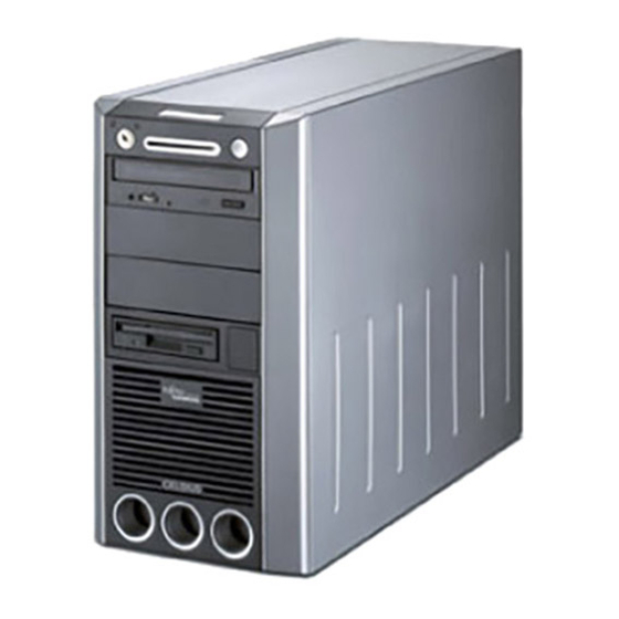
Related Manuals for Fujitsu Siemens Computers CELSIUS M430


Summary of Contents for Fujitsu Siemens Computers CELSIUS M430
- Page 1 Workstation English Operating Manual CELSIUS M430 / CELSIUS W Operating Manual...
- Page 2 Are there ..any technical problems or other questions which you would like to be clarified? Please contact: ● ● your sales partner ● your sales outlet Further information can be found in the "Safety" and "Warranty" manuals. The latest information on our products, tips, updates, etc., can be found on the internet under: http://www.fujitsu-siemens.com...
- Page 4 This manual was produced by cognitas. Gesellschaft für Technik-Dokumentation mbH – www.cognitas.de Published by Fujitsu Siemens Computers GmbH AG 0405 04/05 Edition 1 Order No.: A26361-K665-Z126-1-19...
-
Page 5: Operating Manual
Introduction Important notes CELSIUS M430 / Preparing for use CELSIUS W Operation Troubleshooting and tips Operating Manual System expansions Technical data Index April 2005 edition... - Page 6 CELSIUS is a registered trademark of Fujitsu Siemens Computers GmbH. Microsoft, MS, MS-DOS, Windows, Windows NT, Windows 2000 and Windows XP are registered trademarks of Microsoft Corporation. VESA and DPMS are trademarks of Video Electronics Standards Association. PS/2 is a registered trademark of International Business Machines, Inc.
-
Page 7: Table Of Contents
Contents Your CELSIUS M430 / CELSIUS W....................1 Notational conventions ......................... 2 Important notes ..........................3 Safety notes............................3 Energy saving, disposal and recycling ..................3 CE marking........................... 3 FCC Class B Compliance Statement ....................4 Transporting the workstation ........................ 5 Cleaning the workstation ........................ - Page 8 Contents Troubleshooting and tips .........................29 Installing new software........................29 Power-on indicator remains unlit after you have switched on your device..........29 The screen stays blank ........................30 No mouse pointer displayed on the screen..................31 The floppy disk cannot be read or written ...................31 Time and/or date is not correct ......................32 Error messages on the screen ......................32 Restoring the hard disk contents ......................32...
-
Page 9: Edition
Your CELSIUS M430 / CELSIUS W ... is available with various configuration levels with different hardware and software. In addition, you can install accessible drives (e.g. DVD drive), hard disks and other boards. This operating manual tells you how to put your workstation into operation and how to operate it in daily use. -
Page 10: Notational Conventions
Your CELSIUS M430 / CELSIUS W Notational conventions The meanings of the symbols and fonts used in this manual are as follows: indicates information which is important for your health or for preventing physical damage. indicates important information which is required to use the system properly. -
Page 11: Important Notes
Important notes In this chapter you will find information regarding safety which it is essential to take note of when working with your workstation. Safety notes Pay attention to the information provided in the "Safety" manual and in the following safety notes. -
Page 12: Fcc Class B Compliance Statement
● Consult the dealer or an experienced radio/TV technician for help. Fujitsu Siemens Computers GmbH is not responsible for any radio or television interference caused by unauthorised modifications of this equipment or the substitution or attachment of connecting cables and equipment other than those specified by Fujitsu Siemens Computers GmbH. The correction of interferences caused by such unauthorised modification, substitution or attachment will be the responsibility of the user. -
Page 13: Transporting The Workstation
Important notes Transporting the workstation Transport all parts separately in their original packaging or in a packaging which protects them from knocks and jolts, to the new site. Do not unpack them until all transportation manoeuvres are completed. Cleaning the workstation Turn off all power and equipment switches and pull the power plug out of the grounded mains outlets. -
Page 15: Preparing For Use
Preparing for use Please take note of the safety information in the "Important notes" chapter. Unpacking and checking the delivery It is recommended not to throw away the original packaging material! It may be required for reshipment at some later date. ►... -
Page 16: Setting Up The Workstation
Preparing for use Setting up the workstation When installing your workstation, give consideration to the recommendations and safety notes in the "Safety" manual. Set up your workstation only in its correct orientation. We recommend that you place your device on a surface with good anti-slip qualities. In view of the multitude of different finishes and varnishes used on furniture, it is possible that the rubber feet will mark the surface they stand on. - Page 17 Preparing for use ► Depending on the connector, plug the monitor power cable into either the monitor socket of the workstation (1) or the grounded mains outlet (2). On units with a main power switch, we recommend that you connect the monitor to the monitor socket of the workstation if possible.
-
Page 18: Connecting The Mouse
Preparing for use Connecting the mouse Depending on the equipment level selected, your workstation will be supplied with a PS/2 mouse or a USB mouse. Connecting a PS/2 mouse ► Connect the PS/2 mouse to the PS/2 mouse port on the workstation. Connecting USB mouse ►... -
Page 19: Connecting The Workstation To The Mains Voltage
Preparing for use Connecting the workstation to the mains voltage 100 V - 125 V 200 V - 240 V a = Notch for inserting the screwdriver ► Check the voltage setting. If you have a wide-range power supply, the appropriate voltage will be automatically selected. - Page 20 Preparing for use ► Plug the power cable into the workstation (1). ► Plug the power plug into the grounded mains outlet (2). A26361-K665-Z126-1-19, edition 1...
-
Page 21: Initial Switch-On: Software Will Be Installed
Preparing for use Initial switch-on: Software will be installed If the workstation is integrated into a network, the user and server details as well as the network protocol are required. Contact your network administrator if you have any questions about these settings. - Page 22 Preparing for use 1 = Main switch 0 = Workstation is switched off 2 = ON/OFF switch I = Workstation is ready-to-operate ► Switch on the workstation with the main power switch on the back panel if present. ► Press the ON/OFF switch on the front of the workstation. The corresponding indication then appears on the LCD or the relevant indicators light (see "Indicators on the workstation").
-
Page 23: Installing The Software
Preparing for use Installing the software ► During installation, follow the instructions on screen. Consult the operating system manual if there is anything unclear about the requested input data. You will find further information about the system, drivers, utilities, updates, manuals etc. on the "Drivers &... -
Page 24: Connections On The Workstation
Preparing for use Connections on the workstation The ports for external devices are on the rear and on the front of the workstation. The ports available on your workstation depend on the configuration level you have selected. The standard ports are marked with the symbols shown below (or similar). -
Page 25: Connecting External Devices To The Serial Port
Preparing for use Connecting external devices to the serial port External devices can be connected to the serial port (e.g. a modem). ► Connect the data cable to the external device. ► Connect the data cable to the serial port For an exact description of how to connect external devices to the serial port, please refer to the device documentation. -
Page 26: Connecting External Devices To The Usb Ports
Preparing for use Connecting external devices to the USB ports You can connect a wide range of external devices to the USB port (e.g. printer, scanner, modem or keyboard). USB devices are hot-pluggable. This means you can connect and disconnect devices while your operating system is running. -
Page 27: Operation
Operation Switching the workstation on ► If necessary, switch the monitor on (see the operating manual for the monitor). ► Switch on the workstation with the main power switch on the rear of the workstation (if present). ► Press the ON/OFF switch on the front of the workstation. The corresponding indication appears on the LCD (see "Indicators on the workstation") or the operating indicator lights green, the workstation starts up. -
Page 28: Indicators On The Workstation
Operation Indicators on the workstation The indicators are on the front of the workstation. Which indicators are available on your workstation depends on the configuration level you have selected. 1 = LCD 3 = Floppy disk indicator 2 = CD-ROM indicator 1 - LCD The LCD lights up as soon as the workstation is switched on. - Page 29 Operation LAN connection appears on the LCD as soon as the workstation is connected to a LAN. LAN access appears on the LCD as soon as the workstation sends or receives data over the LAN. Message Appears on the LCD when an incoming message (mail, fax) is waiting. This symbol only appears if you use software that supports this function.
-
Page 30: Keyboard
Operation Keyboard 1 = Function keys 4 = Cursor keys 2 = Power button (optional) 5 = Numeric keypad (calculator keypad) 3 = Alphanumeric keypad The illustrated keyboard is an example and may differ from the model you use. Important keys and key combinations The following description of keys and key combinations refers to MS Windows. - Page 31 Operation Shift key enables upper-case letters and the upper key symbols to be used. Alt Gr (e.g. German keyboard) produces a character shown on the right-hand side of a key (e.g. the character @ on Alt Gr the key Q ). Num key Switches the numeric key pad between the number ("Num"...
-
Page 32: Working With Floppy Disks
Operation Working with floppy disks Follow the instructions supplied by the vendor of the floppy disks. Never clean the floppy disk drives with cleaning disks. Any attempt would destroy the read/write head in the disk drive within 20 seconds. 1 = Insertion direction 2 = Label area 3 = Write protection tab for a 1.44 Mbyte floppy disk 4 = Identification of a 1.44 MB floppy disk or write protect switch on a 120 MB floppy disk... -
Page 33: Settings In Bios Setup
Operation Settings in BIOS Setup The BIOS Setup menu allows you to set your hardware configuration and system functions of the workstation. When the PC is delivered, the default entries are valid (see "BIOS Setup" manual and if necessary manual for the mainboard). You may customise these settings to your requirements in the BIOS Setup. -
Page 34: Anti-Theft Protection And Lead-Sealing
Operation Anti-theft protection and lead-sealing Large eye Small eye Device for "Kensington Lock" There are three ways to protect your workstation from theft: ● with the Kensington Lock device (3) and with a Kensington MicroSaver. ● with a chain (lead-seal) ●... -
Page 35: Bios Setup Security Functions
Operation BIOS setup security functions The Security menu in BIOS Setup offers you various options for protecting your personal data against unauthorised access, e.g.: ● Preventing unauthorised BIOS Setup entry ● Preventing unauthorised system access ● Preventing unauthorised access to the settings of boards with their own BIOS ●... - Page 36 Operation SystemLock permissions You can initialise a SmartCard with one of the following permissions: System The system starts following entry of the user PIN. You can change the user PIN. Setup You can open and change the BIOS Setup and change the user PIN. System+Setup The system starts following entry of the user PIN.
-
Page 37: Troubleshooting And Tips
Troubleshooting and tips Take note of the safety notes in the "Safety" manual and in the "Preparing for use" chapter, when you connect or disconnect cables. If a fault occurs, try to correct it as described in the following places: ●... -
Page 38: The Screen Stays Blank
Troubleshooting and tips The screen stays blank If your screen remains blank this may be due to the following: Monitor is switched off ► Switch your monitor on. Power saving has been activated (screen is blank) ► Press any key on the keyboard. ►... -
Page 39: No Mouse Pointer Displayed On The Screen
Troubleshooting and tips Wrong monitor has been set under Window XP ► Restart the workstation. ► Press F8 while the system is booting. Either the Windows Advanced Start Options menu or the menu for selecting the operating system appears. ► If the menu for selecting the operating system appears, press F8 . -
Page 40: Time And/Or Date Is Not Correct
Troubleshooting and tips Time and/or date is not correct You can set the time and date in the BIOS Setup or in the operating system. ► Set the time and date. If the time and date are repeatedly wrong when you switch on your PC, the on-board battery is flat. -
Page 41: System Expansions
System expansions As the PC has to be shut down in order to install/deinstall system hardware components, it is a good idea to print out the relevant sections of this chapter. It may be necessary to update the BIOS when carrying out a system expansion or hardware upgrade. -
Page 42: Opening The Casing
System expansions Opening the casing ► Switch off the workstation. The workstation must not be in the energy-saving mode. Please take note of the safety information in the "Important notes" chapter. Pull the power plug out of the mains outlet. Only insert the power plug after you have closed the casing. -
Page 43: Closing The Casing
System expansions Closing the casing ► Push the side cover from above in the direction of the arrow (1) until it engages. Depending on the configuration level, your workstation will be supplied with or without a casing lock. ► Lock the casing again if necessary. ►... -
Page 44: Removing And Installing The Fan
System expansions Removing and installing the fan Your workstation may or may not have a fan, depending on the configuration. The fan must be removed whenever you install a board or upgrade the main memory. Remove the fan ► Open the casing (see "Opening the casing"). ►... - Page 45 System expansions Installing the fan ► Slide the fan into the guide rails in the direction of the arrow (1). ► Fasten the fan with the screw (2). ► Close the casing (see "Closing the casing"). A26361-K665-Z126-1-19, edition 1...
-
Page 46: Installing And Removing A Board
System expansions Installing and removing a board Please take note of the section "Information about boards". The number, position and arrangement of the board slots on the mainboard can be found in the manual for the mainboard. Boards may already be installed when the device is shipped. Installing a board ►... - Page 47 System expansions ► Make the required settings for the board. ► Push the board up to its slot (1). ► Press the board into the slot so that it engages. ► If necessary, connect the cables. ► Close the locking rail (2) and press on the locking mechanism in the direction of the arrow. The word "PUSH"...
-
Page 48: Removing A Board
System expansions Removing a board ► Open the casing (see "Opening the casing"). For workstations with a fan only: ► Remove the fan (see "Remove the fan"). ► Disconnect the cables connected to the board. ► Press the unlocking mechanism (1) down and open the locking rail (2). The word "PRESS" is embossed on the unlocking mechanism. - Page 49 System expansions ► Push the slot cover into the slot (1). Ensure that the projection (a) on the slot cover engages into the appropriate recess. If it does not, you will find it difficult to close the locking rail. There is a danger of damage. ►...
-
Page 50: Low-Profile Boards
System expansions Low-Profile boards For units with a particularly low overall height, there are so-called low-profile boards with a slot cover with a lower overall height to match the low-profile units. To also install these low-profile boards in normal board slots, you must mount a corresponding slot adapter beforehand Two-piece rear covers are fitted into the slots intended for low-profile boards. -
Page 51: Installing And Removing Drives
System expansions Installing and removing drives The PC casing can accommodate a total of eight drives: ● four accessible drives (three 5¼" drives and one 3½" drive) ● four non-accessible drives (3½" drives) "Accessible drives" are e.g. DVD or CD ROM drives, into which a data carrier can be inserted from outside. -
Page 52: Attaching The Front Panel
System expansions ► Detach the plastic hook on the front panel of the casing and carefully remove the front panel. If you pull too hard, you may loosen or damage the LCD cable. In a system with an LCD, the cable is long enough so that you can carefully place it to one side with the front panel. -
Page 53: Installing An Accessible Drive
System expansions Installing an accessible drive ► Open the casing (see "Opening the casing"). ► Remove the front (see "Removing the front panel"). ► Press the EasyChange rails (1) together and pull the empty slide-in module out of the casing (2). A26361-K665-Z126-1-19, edition 1... - Page 54 System expansions ► Pull the EasyChange rails off the empty slide-in module. Do not dispose of the empty slide-in module. For cooling, protection against fire, and in order to comply with EMC regulations, you must refit the empty slide-in module if you remove the drive again later.
- Page 55 System expansions ► Press the EasyChange rails into the provided holes. ► Push the accessible drive into the casing (1) until the EasyChange rails engage. ► Plug the data and the power supply connectors into the drive. Make sure the polarity is correct. ►...
-
Page 56: Removing An Accessible Drive
System expansions Removing an accessible drive ► Open the casing (see "Opening the casing"). ► Remove the front (see "Removing the front panel"). ► Pull the data and the power supply connectors from the desired drive. ► Press the EasyChange rails together (1) and pull the drive out of the casing (2). ►... - Page 57 System expansions ► Pull the EasyChange rails off the drive. ► Press the EasyChange rails into the holes provided in the empty slide-in module. ► Slide the slide-in module into the casing until it engages noticeably. ► Attach the front panel (see "Attaching the front panel"). ►...
-
Page 58: Replacing The Floppy Disk Drive
System expansions Replacing the floppy disk drive ► Open the casing (see "Opening the casing"). ► Remove the front (see "Removing the front panel"). ► Disconnect the cables connected to the floppy disk drive. ► If it is present, pull the cable of the front USB or USB-audio interface from the mainboard (see also the manual for the mainboard). - Page 59 System expansions ► Pull the EasyChange rails off the floppy disk slide-in module. ► Remove the screws (1) on both sides of the slide-in module. ► Pull the disk drive out of the slide-in module (2). Installing the floppy disk drive ►...
- Page 60 System expansions ► Press the EasyChange rails into the provided holes. ► Slide the floppy disk slide-in module into the casing (1) until it engages noticeably. ► Fit the data and power supply connectors to the floppy disk drive. ► If it is present, pull the cable of the front USB or USB-audio interface from the mainboard (see also the manual for the mainboard).
-
Page 61: Installing Or Removing The Hard Disk Drive
System expansions Installing or removing the hard disk drive ► Open the casing (see "Opening the casing"). Removing the cover ► Loosen the screw (1). ► Fold out the cover (2). A26361-K665-Z126-1-19, edition 1... - Page 62 System expansions Installing a hard disk drive ► Take the new hard disk drive out of its packaging. ► Make the required settings (e.g. master-slave settings or SCSI-ID) on the drive. ► Secure the EasyChange rails on the side of the hard disk by inserting the upper pins of the EasyChange rail in the corresponding holes of the hard disk.
- Page 63 System expansions Installing the cover plate ► Set the cover plate into the casing such that the projections (a) engage into the appropriate recesses (1). ► Close the cover. Ensure that the power supply and data cables are not pinched. Fasten the cover with the screw (2).
- Page 64 System expansions Removing a hard disk drive ► Open the casing (see "Opening the casing"). ► Remove the cover (see "Removing the cover "). ► Disconnect all cables connected to the drive (data cable, power supply cable). ► Press the EasyChange rails in the direction of the arrows (1). ►...
-
Page 65: Replacing The Smartcard Reader
System expansions Replacing the SmartCard reader Removing a SmartCard reader ► Open the casing (see "Opening the casing"). ► Remove the front (see "Removing the front panel"). ► Disconnect the plug of the SmartCard data cable from the mainboard (see the manual for the mainboard). - Page 66 System expansions Installing a SmartCard reader ► Slide the SmartCard reader into the supplied mounting (1) with the component side upwards and fix it in place with the screws (2). ► Connect the data cable to the SmartCard reader. ► Place the carrier on the guide clips in the casing.
-
Page 67: Installing And Removing Front Usb Or Usb Audio Ports
System expansions Installing and removing front USB or USB audio ports You can install the following variants in the recess next to the floppy disk drive: ● two USB ports ● a USB port combined with two audio ports ● two USB interfaces combined with two audio ports Each of the audio ports have the connections Headphone OUT and Microphone IN. - Page 68 System expansions ► Pull the EasyChange rails off the floppy disk slide-in module. ► Detach the locking mechanisms (1) and remove the front bezel of the floppy disk slide-in module (2). ► Remove the blind cover from the bezel of the floppy disk slide-in module (3). A26361-K665-Z126-1-19, edition 1...
- Page 69 System expansions ► Slide the USB or USB-audio interface through the hole provided (1). First slide the tongue into the upper opening. ► Fasten the USB or USB audio ports with the screw (2). ► If present, insert the appropriate interface frame into the slide-in module bezel (1). ►...
- Page 70 System expansions ► Press the EasyChange rails into the provided holes. ► Slide the floppy disk slide-in module into the casing (1) until it engages noticeably. Fit the data and power supply connectors to the floppy disk drive. ► Connect the USB cable and, if necessary, the audio cable to the corresponding connector on the mainboard (see also the manual for the mainboard).
- Page 71 System expansions Removing front USB or USB audio ports ► Open the casing (see "Opening the casing"). ► Remove the front (see "Removing the front panel"). ► Detach the USB data cable and, if present, the audio data cable from the mainboard (see the manual for the mainboard).
- Page 72 System expansions ► Detach the locking mechanisms (1) and remove the bezel of the floppy disk slide-in module (2). ► If present, remove the interface frame (3) from the cover of the floppy disk slide-in module. ► Remove the screw (1) and then remove the USB or USB-audio interface (2). A26361-K665-Z126-1-19, edition 1...
- Page 73 System expansions ► Insert the blanking plate into the slide-in module bezel (1). ► Place the cover on the floppy disk slide-in module again (2). ► First attach the cover at the bottom and then push the upper tongues into place until they engage (3).
- Page 74 System expansions ► Slide the floppy disk slide-in module into the casing (1) until it engages noticeably. ► Fit the data and power supply connectors to the floppy disk drive. ► Attach the front panel (see "Attaching the front panel"). ►...
-
Page 75: Installing Wlan Module
System expansions Installing WLAN module ► Open the casing (see "Opening the casing"). ► Remove the front (see "Removing the front panel"). ► Detach the USB data cable and, if present, the audio data cable from the mainboard (see the manual for the mainboard). - Page 76 System expansions ► First attach the cover at the bottom and then push the upper tongues into place until they engage (2). ► Press the EasyChange rails into the provided holes. A26361-K665-Z126-1-19, edition 1...
- Page 77 System expansions ► Slide the slide-in module into the casing until it engages noticeably. ► Connect the USB data cable of the WLAN module onto the corresponding connector on the mainboard (also see manual for the mainboard). ► Attach the front panel (see "Attaching the front panel"). ►...
-
Page 78: Removing Wlan Module
System expansions Removing WLAN module ► Open the casing (see "Opening the casing"). ► Remove the front (see "Removing the front panel"). ► Detach the USB data cable of the WLAN module and, if present, the audio data cable from the mainboard (see the manual for the mainboard). - Page 79 System expansions ► Detach the locking mechanisms (1) and remove the bezel (2). ► Remove the screws on both sides of the slide-in module (1). ► Pull the WLAN module out of the slide-in module (2). A26361-K665-Z126-1-19, edition 1...
- Page 80 System expansions ► First attach the bezel at the bottom (1) and then push the upper tongues into place until they engage (2). ► Press the EasyChange rails into the provided holes. A26361-K665-Z126-1-19, edition 1...
- Page 81 System expansions ► Slide the slide-in module into the casing until it engages noticeably. ► Attach the front panel (see "Attaching the front panel"). ► Close the casing (see "Closing the casing"). A26361-K665-Z126-1-19, edition 1...
-
Page 82: Extensions To The Mainboard
System expansions Extensions to the mainboard Details on whether you can upgrade the main memory or the processor are provided in the manual for the mainboard. In order to upgrade or replace the processor, you must first remove the ventilation cover. -
Page 83: Upgrading Main Memory
System expansions Upgrading main memory For workstations with a fan only: ► Remove the fan (see "Remove the fan"). ► Upgrade the memory according to the description in the manual for the mainboard. For workstations with a fan only: ► Install the fan (see "Installing the fan"). -
Page 84: Swinging The Power Supply In
System expansions ► Press the locking lug in the direction of the arrow; the battery jumps somewhat out of the holder (1). ► Remove the battery (2). ► Push the new lithium battery of the identical type into the holder (3) and press it downward until it engages (4). -
Page 85: Technical Data
Technical data Electrical data Regulations complied with: EN 60950 UL 60950 CSA 22.2 No.950 Protection class: Rated voltage range (automatic, power supply 250 and 300 W): 100 V -240 V Frequency: 50 Hz - 60 Hz Max. rated current ● Workstation with monitor socket: 100 V -240 V/7.0 A -3.5 A ●... -
Page 87: Index
Index 3 1/2-inch drive 43 Cursor keys 22 5 1/4-inch drive 43 Data protection 25 Access permission, SmartCard 27 Date, not correct 32 Alt Gr key 23 Device drivers Anti-theft protection 26 parallel port 17 Audio input 16 serial port 17 Audio output 16 USB 18 Devices... - Page 88 Index Floppy disk Keyboard 22 cannot read 31 connecting 10 cannot write 31 important keys 22 inserting 24 port 16 removing 24 Keyboard port 8, 10 working with 24 Keypad, alphanumeric 22 write-protection 24, 31 write-protection, disabling 24 Floppy disk drive LAN port 16 changing 50 LCD 20...
- Page 89 Index Numeric keypad 22 SCSI port 16 Security functions BIOS Setup 27 SmartCard 27 ON/OFF switch 14, 22 SmartLock 27 Serial port 16, 17 connecting devices 17 Packing material 7 port 16 unpacking 7 settings 17 Parallel port 16, 17 Setup, see BIOS Setup connecting devices 17 Shift key 23...
- Page 90 Index USB port 10, 16, 18 connecting 11 connecting devices 18 connecting devices 15 removing 63 extensions 33 indicators 20 lead-seal 26 locking 25, 35 Ventilation area 8 locking mechanically 25 Video workstation 8 opening 34 ports 16 ready-to-operate 19 Warm boot 23 setting up 8 WLAN module...
Need help?
Do you have a question about the CELSIUS M430 and is the answer not in the manual?
Questions and answers