Pacific energy fusion gas Installation And Operating Instructions Manual
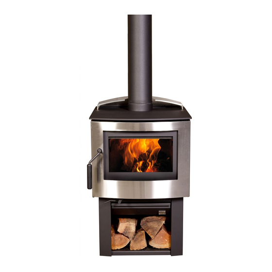
Fusion gas direct vent freestanding stove
Hide thumbs
Also See for fusion gas:
- Installation & operation manual (16 pages) ,
- Installation and operating instructions manual (20 pages)
Table of Contents
Advertisement
IMPORTANT:
THESE INSTRUCTIONS ARE TO
REMAIN WITH THE HOMEOWNER
WARNING: If the information in
these instructions is not followed
exactly, a fire or explosion may
result causing property damage,
personal injury or loss of life.
– Do not store or use gasoline or
other flammable vapours and
liquids in the vicinity of this or
any other appliance.
– WHAT TO DO IF YOU SMELL GAS
• Do not try to light any appliance
• Do not touch any electrical
switch; do not use any phone in
your building
• Immediately call your gas supplier
from a neighbour's phone. Follow
the gas supplier's instructions
• If you cannot reach your gas
supplier, call the fire department
– Installation and service must be
performed by a qualified installer,
service agency or the gas supplier.
This appliance may be installed in
an aftermarket permanently
located, manufactured home (USA
only) or mobile home, where not
prohibited by local codes.
This appliance is only for use with
the type of gas indicated on the
rating plate. This appliance is not
convertible for use with other
gases, unless a certified kit is
used.
070905-28
fusion gas
DIRECT VENT
FREESTANDING STOVE
INSTALLATION
OPERATING
INSTRUCTIONS
FSGA
Series A
and
5056.4221
Advertisement
Table of Contents

Related Manuals for Pacific energy fusion gas


Summary of Contents for Pacific energy fusion gas
- Page 1 IMPORTANT: THESE INSTRUCTIONS ARE TO REMAIN WITH THE HOMEOWNER fusion gas WARNING: If the information in these instructions is not followed exactly, a fire or explosion may DIRECT VENT result causing property damage, personal injury or loss of life. FREESTANDING STOVE Series A –...
-
Page 2: Table Of Contents
Contents CAUTION ...........3 SAFETY . -
Page 3: Caution
Energy heater without first reading and understanding this manual. Any installation or operational deviation from the following instructions voids Center of rear the Pacific Energy Warranty and may flue outlet prove hazardous. 21” 18 5/8” This appliance and its individual... -
Page 4: Safety
Caution: Do not use abrasive cleaners It is Pacific Energy’s policy that no Annual Inspection: on glass or any other part of responsibility is assumed by the a) Clean air passageways of this appliance. -
Page 5: Gas Supply
Corner to Appliance 1 in (25 mm) 1” Floor Protection 8 5/8” The Fusion Gas stove may be installed directly on a combustible Alcove Sidewall to Appliance 6 in (152 mm) 48” floor. If the appliance is to be installed... -
Page 6: Top Or Rear Vent Conversion
Top or Rear Vent Conversion The fusion gas stove is set up in the factory as a top vent. To convert to rear vent, use the following proce- dure. Please read the instructions carefully before converting the appli- ance: 1) Remove the two screws securing the air deflector to the rear of the stove (Fig. - Page 7 3) Remove the four screws that fas- ten the vent cover to the back of the appliance, and remove the vent cover (Fig. #3.05). Fig. #3.05 4) Remove the four screws securing the vent adapter to the top of the stove (Fig #3.06).
- Page 8 5) Place the vent cover from step 3 over the top flue outlet (Fig. #3.09) and use four screws to fasten it in place (Fig. #3.10). Fig. #3.09 Fig. #3.10 6) Replace the top plate by hooking the front flange over the mounting brackets (Fig.
- Page 9 7) Place the air deflector back on the top of the appliance and align it so it is spaced evenly from either side. Fasten the air deflector to the rear bracket using two screws (Fig. #3.13). Fig. #3.13 8) Place the optional cast iron Fusion Gas Trivet into the outlet of the air deflector.
-
Page 10: Venting Requirements
Venting Venting For Wall Termination Requirements With No Vertical Rise The Fusion Gas stove installation and venting must conform with local codes or, in the absence of local Fig. #4 14” Snorkel codes, to the current Installation termination Code, CAN/CGA-B149.1 in Canada or the current National Fuel Gas Code, ANSI Z223.1 in the USA. -
Page 11: Wall Termination Venting- With Vertical Rise
Venting For Wall Fig. #6 WALL TERMINATION VENT CHART Termination With 1’ 2’ 3’ 4’ 5’ 6’ 7’ 8’ 9’ 10’ Vertical Rise 10’ 9’ 8’ Any combination of rise and run may be used but must be constrained to the boundaries of this chart. -
Page 12: Roof Termination Venting
Roof Fig. #7 ROOF TERMINATION VENT CHART 40’ Termination Venting Any combination of rise and run may be used but must be constrained to 35’ the bounaries of this chart. If more than 2 elbows are used, reduce horizontal run by 2 feet for each additional elbow. -
Page 13: Vent Terminal Clearances
Vent Terminal VENT TERMINAL MINIMUM Fig. #8 CLEARANCES TO Clearances ADJACENT STRUCTURES Minimum clearances to the vent 36” 24” terminal must be maintained as (91.5 cm) (61 cm) shown in Fig #8 and Fig #9. Measure clearances to the nearest edge of termination hood. -
Page 14: Venting System Components
Venting System Components DURAVENT GS SECURE VENT galv. black galv. black 6" Pipe Length 908B SV 4 L6 SV 4 LB6 9" Pipe Length 907B 12" Pipe Length 906B SV 4 L12 SV 4 LB12 24" Pipe Length 904B SV 4 L24 SV 4 LB24 36"... -
Page 15: Removal Of Window Frame
Removal of Window Frame Removal of Right Hand Side panel 1) Grasp the bottom of the door skin and Fig. #10 pull sharply forward and up to unhook 1) Remove the two screws securing the from the clip on the lower edge (Fig. #10). panel to the firebox (Fig #13). -
Page 16: Adjustment Of Top Vent Damper
Adjustment of Top Vent Damper This appliance has a built in manual 40’ Fig. #14 damper that must be set dependant on the height of the vent. For recommended setting see Fig #14. 35’ The damper only applies to top venting and is preset to 0º... -
Page 17: Log Set Installation
Log Set Installation The ceramic logs are durable and Fig. #16 long lasting when installed properly. However, they are delicate and may be damaged easily if not handled with care. Unpack and inspect log set. There should be a total of 2 logs and one base ceramic. -
Page 18: Lighting Instructions
Lighting Instructions 070905-28 FSGA 5056.4221... -
Page 19: First Fire
First Fire Manual Operation When lit for the first time, the appli- See lighting instructions on page 18. ance will emit a slight odour for a Once the burner has been lit, the couple of hours. This is due to the flame height can be adjusted by curing of paints, sealants and rotating the flame adjustment knob. -
Page 20: Optional Remote Control
Optional Remote Control Fig. #20 to come on in the morning. The Fusion Gas Stove can be c) Press timer again and the "P1 equipped with a thermostatic remote (moon)" will appear, set the time you control. Once a pilot light has been... -
Page 21: Optional Blower
Optional Blower The optional blower kit #FSGA.BLOW OPTIONAL BLOWER WIRING DIAGRAM Fig. #23 is equipped with a three prong power cord and may be installed at any time. Follow installation instructions supplied with the kit. 115 Volts 60 Hz Operation: Rocker Switch Snap Disc Switch 0.5 Amperes... -
Page 22: Propane Conversion
Propane Conversion Note: Factory supplied components must be used to ensure correct input. After conversion confirm proper manifold pressure. 1) Ensure that the burner, pilot and gas supply are turned off and the appliance is cool. 2) Remove door skin by holding the base of the door and pulling up and outwards (Fig. - Page 23 Fig. #33 14) Remove the valve face securing Fig. #30 screw on the left and side using the Fig. #36 special tool provided in this kit (Fig. #33). 9) Remove the pilot hood by pulling it up 18) With a small screwdriver adjust the 15) Insert a small screwdriver into the slot pressure regulator to read 10.5"...
-
Page 24: Body Replacement Parts
33 ..FSGA.7137 ..GLASS FRAME ....1 8 ..FSGA.CAP1..CASTING, FUSION GAS TRIVET ..1 34 . -
Page 25: Burner Replacement Parts
Burner Replacement Parts ITEM PART NUMBER TITLE ITEM PART NUMBER TITLE 1 ..5011.9 ... . . BURNER, DUAL FUEL D0903 ..1 . -
Page 26: Safety Label
Safety Label 070905-28 FSGA 5056.4221... -
Page 27: Notes
Notes 070905-28 FSGA 5056.4221... - Page 28 PACIFIC ENERGY FIREPLACE PRODUCTS LTD. www.pacificenergy.net Toll Free: 1-888-223-0088 2975 Allenby Road, Duncan, BC Canada V9L 6V8 Printed in Canada 5056.4221...
Need help?
Do you have a question about the fusion gas and is the answer not in the manual?
Questions and answers