Table of Contents
Advertisement
IMPORTANT:
THESE INSTRUCTIONS ARE TO
REMAIN WITH THE
HOMEOWNER
WARNING:
If the information in these
instructions is not followed exactly, a fire
or explosion may result causing property
damage, personal injury or loss of life.
-- Do not store or use gasoline or other
flammable vapours and liquids in the
vicinity of this or any other appliance.
-- WHAT TO DO IF YOU SMELL GAS
• Do not try to light any appliance.
• Do not touch any electrical switch; do
not use any phone in your building.
• Immediately call your gas supplier from
a neighbour's phone. Follow the gas
supplier's instructions.
• If you cannot reach your gas supplier,
call the fire department.
-- Installation and service must be
performed by a qualified installer, service
agency or the gas supplier.
This appliance may be installed in an
aftermarket
permanently
manufactured (mobile) home, where not
prohibited by local codes.
This appliance is only for use with the type
of gas indicated on the rating plate. This
appliance is not convertible for use with
other gases, unless a certified kit is used.
251104-24
located,
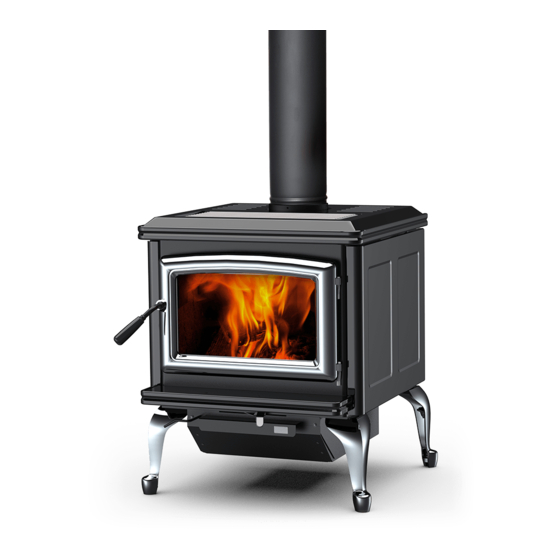
Super 27 Gas
CLGA-A
Classic Gas
and
SERIES A
DIRECT VENT HEATER
INSTALLATION
AND OPERATING
INSTRUCTIONS
5056.423
Advertisement
Table of Contents

Related Manuals for Pacific energy Super 27 Gas


Summary of Contents for Pacific energy Super 27 Gas
- Page 1 • If you cannot reach your gas supplier, call the fire department. -- Installation and service must be performed by a qualified installer, service Classic Gas agency or the gas supplier. This appliance may be installed in an aftermarket permanently...
-
Page 2: Table Of Contents
PRIMARY AIR ADJUSTMENT ............ 17 OPTIONAL WALL SWITCH OR THERMOSTAT ......18 OPTIONAL BLOWER ..............19 REPLACEMENT PARTS - Classic Gas ........20 REPLACEMENT PARTS - Super 27 Gas........21 REPLACEMENT PARTS - Burner Assembly ......22 RATING LABEL ................23... -
Page 3: Caution
This condition is manual. Any installation or operational deviation from the temporary. Open doors and windows to ventilate following instructions voids the Pacific Energy Warranty and area. If optional fan kit has been installed, place fan may prove hazardous. -
Page 4: Safety
Clean air passage ways of excessive lint and dust buildup from carpeting, bedding material, etc. The flow of ventilation It is Pacific Energy’s policy that no responsibility is assumed air must not be obstructed. by the Company or by any of its employees or... -
Page 5: Base Kit Installation
1) Carefully remove crate top, side supports and plastic cover bag. 2) Leave the unit on the pallet. Leg Kit (Classic Gas model only) DOOR KIT INSTALLATION 1) Remove the 1/2" nuts and washers from the studs on the bottom corners of the stove using a 3/4" wrench. Save nuts and Remove door from packing box and inspect. -
Page 6: Gas Supply
2.9" wc 2" FLOOR PROTECTION 9 3/4" Both, the Classic Gas and Super 27 Gas Heaters, may be 48" installed directly on a combustible floor. If the appliance is to be installed directly on carpeting, combustible floor tile or 5"... -
Page 7: Venting Requirements
The Classic Gas and Super 27 Gas Heaters are tested and Consult your local Building Codes before beginning the certified for use with SIMPSON DURA-VENT DIRECT VENT installation. -
Page 8: Wall Termination Venting
WALL TERMINATION VENTING Fig. # 6 A minimum vertical rise of 2 feet is required for any wall termination (see Fig. #5). For horizontal runs greater than 1 foot, increase vertical rise equally. At 4 feet of rise, the horizontal run may increase up to and must not exceed 10 feet. -
Page 9: Roof Termination Venting
ROOF TERMINATION VENTING Fig. # 7 A vertical rise of up to 40 feet is permitted with no horizontal offset. If an offset is required, ensure that the vertical rise is 1 foot greater than the horizontal offset. Horizontal offset must not exceed 10 feet. -
Page 10: Vent Restrictor Adjustment
VENT RESTRICTOR Fig. # 9 ADJUSTMENT WALL AND ROOF A vent restrictor damper is built into the appliance to adjust the TERMINATION flow rate of exhaust gases. This ensures proper flames for the RESTRICTOR wide variety of vent configurations. POSITION Refer to the chart for the correct damper angle for the amount of vent in your installation. -
Page 11: Vent Terminal Clearances
VENT TERMINAL CLEARANCES Fig # 11 Minimum clearances to the vent teminal must be maintained as shown in figures #10 and #11. Measure clearances to the nearest edge of termination hood. NOTE: Vent terminal must not be recessed into a wall or siding. Follow vent terminal manufacturers installation instructions. -
Page 12: Glowing Embers
Fig. # 12 Venting System Components Dura-Vent GS Secure Vent galv. black galv. black 6" Pipe Length ............. 908 ..... 908B ......SV 4 L6 ..SV 4 LB6 9" Pipe Length ............. 907 ..... 907B 12" Pipe Length ............906 ..... 906B ......SV 4 L12 ..SV 4 LB12 24"... -
Page 13: Input Rate Conversion
INPUT RATE CONVERSION Fig. # 13b To convert from stock natural gas Btu input rate of 41750 to reduced input of 25000, the following procedure should be followed: Ensure the burner, pilot and fuel supply are turned off, and the appliance has cooled. Note logs position and carefully remove (if installed). -
Page 14: Propane Conversion
PROPANE CONVERSION Fig. # 14a Rear Air Deflector The appliance can be converted to Propane Gas by changing the burner orifice and pilot orifice and converting the valve. To convert, proceed as follows: Burner Orifice (see INPUT RATE CONVERSION section) Ensure the burner, pilot and fuel supply are turned off, and the appliance has cooled. -
Page 15: Log Set
LOG SET Step 3 Mid-left Log Placement (log #3) Note: Embers should be in place prior to installing logs. Unpack and inspect log set. There should be a total of 6 logs. Gas and vent connections should be made before installing log set. -
Page 16: Lighting Instructions
LIGHTING INSTRUCTIONS FOR YOUR SAFETY READ BEFORE LIGHTING phone in your building. WARNING: If you do not follow these - Immediately call your gas supplier from a neigh- instructions exactly, a fire or explosion bour's phone. Follow the gas supplier's instruc- may result causing property damage, tions. -
Page 17: Operation
OPERATION PRIMARY AIR ADJUSTMENT The heater comes equipped with an "ON-OFF" rocker switch. This appliance is provided with primary air adjustment, which This switch is conveniently located on the control panel just affects flame height and quality. behind the access door. Adjustment is possible to compensate for varying field Once a pilot light has been established, and the gas valve conditions, such as vent system configuration or altitude. -
Page 18: Optional Wall Switch Or Thermostat
OPTIONAL WALL SWITCH OR THERMOSTAT Recommended Thermostat WARNING: Do not connect electricity to the gas control Wire Size valve or control wiring system of this unit. No electrical connection is required for this system operation. Wire Size Max. Length The self-generating pilot provides current for the remote wall 14 ga ...... -
Page 19: Optional Blower
OPTIONAL BLOWER The optional blower kit #BLOW.G1A is equipped with a three prong power cord and may be installed at any time. Follow installation instructions supplied with the kit. Operation: The optional circulating air blower is either thermostatically or manually controlled. Set to auto, the fan will only turn on if the appliance is at operating temperature. -
Page 20: Replacement Parts - Classic Gas
16 ..FIREBOX TOP SHIELD ..........7037 ..OPTIONAL BLOWER (not shown) ....BLOW.G1A All parts may be ordered from your nearest Pacific Energy Gas Stove dealer. Contact Pacific Energy for the location of the dealer nearest you. When ordering porcelain finish parts, please specify the appro- priate colour code as follows: Black ...... -
Page 21: Replacement Parts - Super 27 Gas
18 ..FLUE ADAPTER GASKET ........2761 ..OPTIONAL BLOWER (not shown) ....BLOW.G1A 19 ..VENT ADAPTER ..........5096.812 All parts may be ordered from your nearest Pacific Energy dealer. Contact Pacific Energy for the location of the dealer nearest you. -
Page 22: Replacement Parts - Burner Assembly
REPLACEMENT PARTS - Burner Assembly (WHEN ORDERING, INCLUDE PART NUMBER WITH DESCRIPTION) ITEM DESCRIPTION PART NO. ITEM DESCRIPTION PART NO. 1 ..GAS VALVE ............5007.05 11 ..WASHER, FIBER ............5043 2 ..EXTENSION KNOB, ON/OFF ......5007.315 12 ..SPRING NUT .............. 5044 3 .. -
Page 23: Rating Label
RATING LABEL PROPANE CONVERSION RATING LABEL... - Page 24 Pacific Energy Fireplace Products Ltd. 2975 Allenby Rd, Duncan, B.C. V9L 6V8 Phone: 250-748-1184 Web site: http://www.pacificenergy.net Printed in Canada...
Need help?
Do you have a question about the Super 27 Gas and is the answer not in the manual?
Questions and answers