Pacific energy MIRAGE 30 A SERIES Installation And Operating Instructions Manual
Hide thumbs
Also See for MIRAGE 30 A SERIES:
Table of Contents
Advertisement
INSTALLER:
Leave this manual with the appliance.
CONSUMER:
Retain this manual for future reference.
WARNING: If the information in these
instructions is not followed exactly a fire or
explosion may result causing property
damage, personal injury or death.
FOR YOUR SAFETY
Do not store or use gasoline or other
flammable vapours and liquids in the vicinity
of this or any other appliance.
WHAT TO DO IF YOU SMELL GAS
• Do not try to light any appliance.
• Do not touch any electrical switch.
• Do not use any phone in your building.
• Immediately call your gas supplier
from a neighbour's phone. Follow the
gas supplier's instructions.
• If you cannot reach your gas supplier
call the fire department.
Installation and service must be performed
by a qualified installer, service agency or the
gas supplier.
This appliance may be installed in an
aftermarket permanently located,
manufacture home (USA only) or mobile
home, where not prohibited by local codes.
This appliance is only for use with the type of
gas indicated on the rating plate. This
appliance is not convertible for use with
other gases unless a certified kit is used.
This appliance is suitable for installation in a
bedroom or bed sitting room.
Visit www. pacificenergy.net for the most up-to-date version of this manual
180516-36
SERIAL #
MIRAGE 30
INSTALLATION AND
OPERATING INSTRUCTIONS
MODEL: MIRAGE 30, SERIES: A
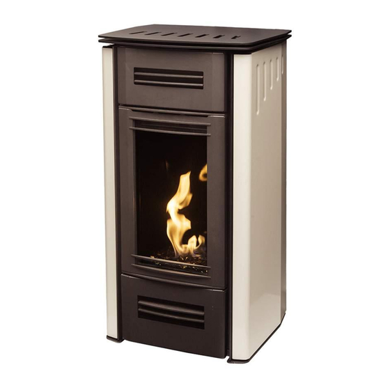
DIRECT VENT FREE STANDING
GAS STOVE
MR30
5055.MR30-A
Advertisement
Table of Contents

Related Manuals for Pacific energy MIRAGE 30 A SERIES


Summary of Contents for Pacific energy MIRAGE 30 A SERIES
-
Page 1: Operating Instructions
INSTALLER: Leave this manual with the appliance. CONSUMER: Retain this manual for future reference. WARNING: If the information in these instructions is not followed exactly a fire or explosion may result causing property damage, personal injury or death. FOR YOUR SAFETY Do not store or use gasoline or other SERIAL # flammable vapours and liquids in the vicinity... -
Page 2: Table Of Contents
Table of Contents Caution ..................3 Manual Bypass of the Remote Control Transmitter ..18 Safety ..................3 Remote Flame Control ............. 18 Important Note for the Commonwealth of Massachusetts ..4 Room Thermostat (Transmitter Operation) ...... 19 Mirage 30 Dimensions ..............5 Smart Thermostat (Transmitter Operation) ...... -
Page 3: Caution
Caution FOR YOUR SAFETY - Do not install or operate your Paci c Energy gas stove without rst reading and understanding this manual. Any installation or oper- ational deviation from the following instructions voids the Paci c Energy ™ Warranty and may prove hazardous. This appliance and its individual shut off valve must be disconnected from gas supply piping system during any pressure testing of that system at test pres- sures in excess of 1/2 psig (3.5 kPa). -
Page 4: Important Note For The Commonwealth Of Massachusetts
Important Note for the Commonwealth of Massachusetts From Massachusetts Rules and Regulations 248 CMR 5.08: For all side wall horizontally vented gas fueled equipment installed in every dwelling, building or structure used in whole or in part for residential purposes, including those owned or operated by the Commonwealth and where the side wall exhaust vent termination is less than seven (7) feet above nished grade in the area of the venting, including but not limited to decks and porches, the following requirements shall be satis ed. -
Page 5: Mirage 30 Dimensions
Mirage 30 Dimensions 27 7/16" (646mm) 45 13/16" (1168mm) 26 3/8" 40 1/8" (1019mm) (670mm) CENTER OF VENTING 9 5/16" (237mm) 21 3/16" (538mm) Figure 1: Mirage 30 Dimensions. 180516-36 5055.MR30-A... -
Page 6: Clearances To Combustibles
Clearances to Combustibles 30” Note on corner placement Refer to minimum clearances Minimum Clearance to as shown in (Figure 3). Combustible Materials 36” Refer to page 7 for venting allowances. INTERIOR SIDE WALL 4” INTERIOR BACK WALL 4” INTERIOR CEILING 36”... -
Page 7: Co-Axial Venting
Co-axial Venting The Mirage 30 can be vented using co-axial components, or co-linear components for venting through an existing replace and chimney. Maximum and minimum venting lengths can be found on the venting charts - co-axial (Figure 4) & co-linear (Figure 5). MIRAGE 18 / 30 CO-AXIAL VENTING CHART Note: The vent must not exceed a total... -
Page 8: Co-Linear Venting
Co-Linear Venting Simpson Duravent High-Wind (cap style) Co-Linear Kit w/Flex (46DVA-CL34) or Simpson Duravent Prairie High wind cap (cap style) Co-Linear Kit w/Flex (46DVA-CL34P) are recommended for use with this appliance. Visit http://www.duravent.com for kit details. Co-Linear Venting Notes: 1. Measure chimney height, cut ex liner (min.10’ •... -
Page 9: Vent Terminal Minimum Clearances
Vent Terminal Minimum Clearances FIXED CLOSED OPEN- FIXED ABLE OPEN- CLOSED ABLE Figure 6: Minimum exterior clearances AREA WHERE TERMINAL GAS METER VENT TERMINAL AIR SUPPLY INLET IS NOT PERMITTED *12 inches (30 cm) min. Clearances above grass, top of plants, wood, combustible veranda, porch, deck, or balcony. *12 inches (30 cm) min. -
Page 10: Venting Components
Venting Components NOTE: Mixing venting components from different manufacturers is inadvisable. 4” x 6 5/8” Rigid Piping Components Cross Reference Figure 8: Venting Components 1. 4” x 6 5/8” Rigid Pipe Components Cross Reference Chart Figure 9: Venting Components 2. 180516-36 5055.MR30-A... -
Page 11: Gas And Electrical Connections
Gas and Electrical Connections Battery holder Gas connection PRG reset Battery holder Electrical connection face plate and manual “ON// REMOTE/OFF” switch Figure 10: Gas and Electircal connection. Gas connection Connect the gas supply line to the 1/2” are tting at the rear of the unit as seen in (Figure 10). -
Page 12: Gas Supply
Gas Supply Servicing of the stove can be performed from the rear of the unit by removing the access panel from the unit. Caution: The gas line should be installed by a quali ed service person in accordance with all building codes. This section is intended as a guide for quali ed technicians installing this stove. -
Page 13: Gas Pressure Testing Procedure
Gas Pressure Testing Procedure Note: To test the gas pressure, turn off the gas supply to the stove before loosening test point screws. Verify gas pressures with the stove lit and at the highest setting. Remove switch cover and back panel and locate the valve as seen in (Figure 11). 2. -
Page 14: Lighting Instructions
Lighting Instructions FOR YOUR SAFETY READ BEFORE LIGHTING WARNING: - Immediately call your gas supplier from a neighbour's phone. Follow If you do not follow these instructions exactly, a the gas supplier's instructions. fire or explosion may result causing property damage, - If you cannot reach your gas supplier, call the fire department. -
Page 15: First Fire
First Fire When lit for the rst time, the gas stove will emit a slight odour for a couple of hours. This is due to the cur- ing of paints, sealants and lubricants used in the manufacturing process. This condition is temporary. Open doors and windows to ventilate area. - Page 16 TRANSMISSION KEY LOCK LOW BATTERY ALARM THERMOSTAT OFF/ ON/SMART ROOM TEMPERATURE * SEE NOTICE REGARDING * SEE NOTICE REGARDING * SEE NOTICE REGARDING THERMOSTAT USE THERMOSTAT USE SMART CPI MODE SET POINT: TEMPERATURE/LEVEL/STATE DIMMER ON DIMMER ON COMFORT FAN Figure 15: Pro ame 2 LCD display. Attention! • Turn off the main gas supply for the appliance during installation or maintenance of the receiver/module device.
-
Page 17: Remote Transmitter Description
Remote Transmitter Description The Pro ame 2 Remote Control consists of two elements: Pro ame 2 Remote Control Transmitter. Pro ame Integrated Fireplace Control (IFC Module) board and a wiring harness to connect the IFC to the gas valve and stepper motor (Figure 11). Transmitter (Remote Control with LCD Display) The Pro ame2 Transmitter uses a streamline design with a simple key layout and an informative LCD display (Figure 15). -
Page 18: Temperature Indication Display
Using the Remote Control Transmitter Temperature indication Display With the remote control transmitter in the “OFF” position, press the thermostat and mode keys at the same time. Look at the LCD screen on the remote control transmit- ter to verify that a C or F is visible to the right of the room temperature display. (Figure 17) &... -
Page 19: Room Thermostat (Transmitter Operation)
Room Thermostat (Transmitter Operation) The remote control transmitter can operate as a room thermostat. The thermostat can be set to a desired temperature to control the comfort level in a room. To activate this function, press the thermostat button (Figure 14), the LCD display on the remote control transmitter will change to show that the room thermostat is “ON”... -
Page 20: Continuous Pilot/Intermittent Pilot (Cpi/Ipi) Selection
Continuous Pilot/Intermittent Pilot (CPI/IPI) selection With the system in the “OFF” position, press the Mode Key (Figure 14) to index to the CPI mode icon (Figure 25). Pressing the Up Arrow Key will activate the Continuous Pilot Ignition mode (CPI). Pressing the Down Arrow Key will return to IPI. -
Page 21: Maintenance
Maintenance CAUTION: Turn off gas and electrical power supply (if applicable) and allow ample time for unit to cool before servicing appliance. It is recommended that the gas stove and its venting should be inspected at least once a year by a quali ed service person. -
Page 22: Propane Conversion
Propane Conversion Before starting the conversion make sure to shut off the gas supply Pilot to the unit and allow stove to cool to room temperature. To convert the gas stove from natural gas to propane, the (GASC.LP18KIT) kit is required. This kit comes with new pilot and burner ori ces as well as a new pressure modulator for the valve. -
Page 23: Door Removal / Installation
Door Removal / Installation Removal Lift the outer door up and pull away from unit. Nuts 2. Remove the 16 3/8” nuts (Figure 31) Carefully remove the glass retainer with the glass by tilting the top towards you. Slits Installation Position the glass retainer’s frame so that the studs on unit align with holes in frame. -
Page 24: Firebox Panel Removal / Installation
Firebox Panel Removal / Installation Note: The burner tray needs to be removed before installation or removal of panels - See (“Burner Tray Installation / Removal” on page 25) Upper back panel Removal Right side Left side panel panel Lower back After removing the burner tray, panel remove the air restrictor plate... -
Page 25: Burner Kit Installation/Removal
Burner Kit Installation/Removal Burner Tray Installation / Removal Installation Interior panels must be installed before burner tray can be installed. The ori ce must be removed prior to burner tray insertion (Figure 41). Remove 2 - 3/8” nuts and extract the ori ce from the rebox. -
Page 26: Optional Media
Optional Media The Driftwood log-set with pebbles requires that any crushed glass media be removed if it is present. The pebbles are spread out around the perimeter of the burner basket after which the glowing embers are evenly spread out inside of the burner basket - (Figure 45). The stove is delivered with two media dividers - a large one for the Mirage 30 model (Figure 43), and a smaller one for the Mirage 18 model. -
Page 27: Removal
Cladding Removal/Installation SCREWS Figure 52: Removing mesh TRIM screen cover. Figure 53: Side panel trim. Figure 51: Mirage 30 front and side panels. Removal The Mirage 30 cladding consists of four panels; the right and left (as seen from the viewer perspective), and an upper and lower panel inset with grills. -
Page 28: Installation
Top positioning screw/post for right hand panel. Figure 56: Mirage 30 upper and Right hand securing lower front panels. screw for upper front panel Figure 54: Upper attach points for side and upper panels. Right hand securing screw for lower front panel Figure 57: Lower front panel and grill. -
Page 29: Air Adjustment
Air Adjustment Venturi adjustment The venturi comes from the factory set to the closed position for use with natural gas. It will need to be adjusted toward the open position for use with propane. To adjust the venturi, the right hand side panel must be removed;... -
Page 30: Replacement Parts
Replacement Parts Description Order Number Replacement Remote Control ........GASC.CNTRLA 2. Replacement Control Module ...........GASC.MODA 3. Replacement Pilot Assembly .......... GASC.PILOTA 4. Replacement Gas Valve ..........GASC.VALVEA 5. Replacement Complete Gas Tray ........GMIR.3801 6. Replacement Door Screen ........GMIR.5002963-A Replacement Blower Kit .......... -
Page 31: Wiring Diagram
Wiring Diagram LAMP COMFORT Caution: Label all wires prior to disconnection when servicing controls. Wiring errors can cause improper and dangerous operation. Verify proper operation after servicing. Figure 63: Electrical diagram for Mirage 18. 180516-36 5055.MR30-A... -
Page 32: Rating Label
FOR USE WITH GLASS DOORS CERTIFIED WITH THE APPLIANCE ONLY / POUR UTILISATION UNIQUEMENT AVEC LES PORTES IN VERRE CERTIFIÉES AVEC L’APPAREIL MINIMUM CLEARANCES TO COMBUSTIBLES / CLAIRANCES MINIMALES AVEC LES COMBUSTIBLE PACIFIC ENERGY Left and Right side are determined when facing the front of the appliance. / Les côtés droit et gauche se déterminent 2975 ALLENBY ROAD en se mettant devant l’appareil et en lui faisant face. - Page 33 180516-36 5055.MR30-A...
- Page 34 180516-36 5055.MR30-A...
- Page 35 180516-36 5055.MR30-A...
- Page 36 © 2016 Copyright Paci c Energy Fireplace Products LTD Reproduction, adaptation, or translation without prior written permission is prohibited, except as allowed under the copyright laws. For technical support, please contact your retailer. Web site: www. pacificenergy.net 2975 Allenby Rd., Duncan, BC V9L 6V8 Printed in Canada...
Need help?
Do you have a question about the MIRAGE 30 A SERIES and is the answer not in the manual?
Questions and answers