
Related Manuals for Advantech AIMB-233


Summary of Contents for Advantech AIMB-233
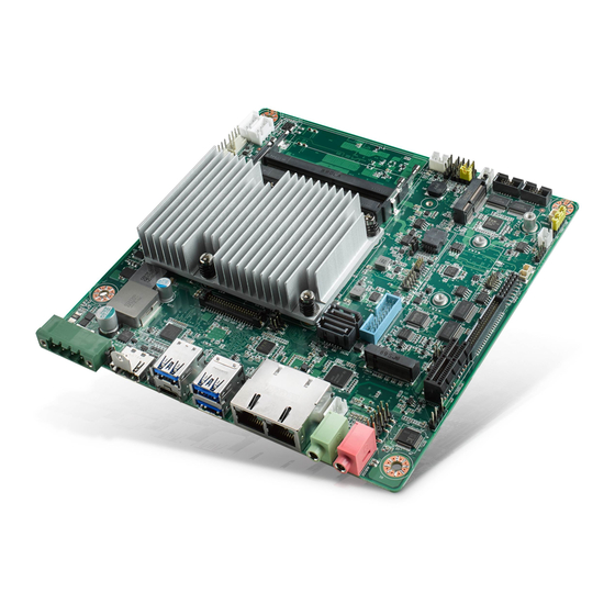
- Page 1 User Manual AIMB-233 ® Intel Core™ 8th Gen ULT Mini-ITX with Type C Alt./HDMI/ LVDS(eDP), 6 COM, Dual LAN, miniPCIe, M.2, PCIex1, DDR4, DC Input...
- Page 2 The documentation and the software included with this product are copyrighted 2018 by Advantech Co., Ltd. All rights are reserved. Advantech Co., Ltd. reserves the right to make improvements in the products described in this manual at any time without notice.
- Page 3 Whether your new Advantech equipment is destined for the labo- ratory or the factory floor, you can be assured that your product will provide the reliability and ease of operation for which the name Advantech has come to be known.
- Page 4 Caution! There is a danger of a new battery exploding if it is incorrectly installed. Do not attempt to recharge, force open, or heat the battery. Replace the battery only with the same or equivalent type recommended by the man- ufacturer. Discard used batteries according to the manufacturer's instructions. AIMB-233 User Manual...
- Page 5 PCIe/PCI AIMB-233G2-U7A1E i7-8665UE 4 x USB 3.1, HDMI, AIMB-233G2-U5A1E i5-8365UE Type C Alt, SATA III Full-size 2 x USB 3.0, (optional) LVDS/eDP 1 x mSATA Mini-PCIe AIMB-233G2-U3A1E i3-8145UE (optional) AIMB-233G2-U0A1E Celeron 2 x USB 2.0, PCIex1 4305UE AIMB-233 User Manual...
- Page 6 Because of Advantech’s high quality-control standards and rigorous testing, most of our customers never need to use our repair service. If an Advantech product is defec- tive, it will be repaired or replaced at no charge during the warranty period. For out- of-warranty repairs, you will be billed according to the cost of replacement materials, service time and freight.
- Page 7 It should be free of marks and scratches and in perfect working order upon receipt. As you unpack the AIMB-233, check it for signs of ship- ping damage. (For example, damaged box, scratches, dents, etc.) If it is damaged or it fails to meet specifications, notify our service department or your local sales repre- sentative immediately.
- Page 8 AIMB-233 User Manual viii...
-
Page 9: Table Of Contents
Table 1.2: Connectors ..............4 Board layout: Jumper and Connector Locations ........5 Figure 1.1 Jumper and Connector Location ........ 5 AIMB-232 Board Diagram ................. 6 Figure 1.2 AIMB-233 Board Diagram .......... 6 Safety Precautions ..................6 Jumper Settings ..................7 1.8.1 How to Set Jumpers.............. - Page 10 2.10 Serial ATA Interface (SATA1~SATA2/SATA_PWR1 ~ SATA_PWR2)... 19 2.11 SATA power connector(SATA_PWR1~2)..........20 2.12 Full Size Mini PCI Express Slot .............. 20 2.13 Front Headphone Connector (FP_AUDIO1) ........... 21 2.14 ATX 12V/DCIN 12V/5V SB Input Power Connector (ATX12V1/DCIN1). 22 2.15 SPI Flash Connector(SPI_CN1) .............
- Page 11 Table A.19:COM1/COM2 Box Header (COM1/COM2)....70 A.20 Watch dog and Open chassis alarm (JWDT1+JOBS1) ......71 Table A.20:Watchdog and Open Chassis Alarm (JWDT1+JOBS1) A.21 Low Pin Count Bus (LPC1) ..............71 Table A.21:Low Pin Count Bus (LPC1)........71 AIMB-233 User Manual...
- Page 12 AIMB-233 User Manual...
-
Page 13: Chapter 1 General Information
Chapter General Information... -
Page 14: Introduction
Introduction AIMB-233 is designed with the Intel® Whiskeylake ULT Dual/Quard Core proces- sors for industrial applications that require both performance computing and enhanced power management capabilities. The motherboard supports Intel whiskeylake ULT Dual Celereon 2.0 GHz / i3 2.2 GHz processors, Quard core i5 1.6 GHz / i7 1.7 GHz processors and DDR4 SO-DIMM 2400 up to 16GB. -
Page 15: Graphics
Boost: 63.28W @12V, 64.73W @24V Measure the maximum current value which system under maximum load (CPU: Top speed, RAM & Graphic: Full loading) Board size: 170 mm x 170 mm (6.69" x 6.69") Board weight: 0.365 kg AIMB-233 User Manual... -
Page 16: Jumpers And Connectors
Jumpers and Connectors Connectors on the AIMB-233 motherboard link it to devices such as hard disk drives and a keyboard. In addition, the board has a number of jumpers used to configure your system for your application. The tables below list the function of each of the board jumpers and connectors. Later sections in this chapter give instructions on setting jumpers. -
Page 17: Board Layout: Jumper And Connector Locations
Table 1.2: Connectors BAT1 Battery connector DC jack 12-24V Main power connector DCIN1 AMP1 Amplifier connector Board layout: Jumper and Connector Locations Figure 1.1 Jumper and Connector Location AIMB-233 User Manual... -
Page 18: Aimb-232 Board Diagram
AIMB-233 Board Diagram Figure 1.2 AIMB-233 Board Diagram Safety Precautions Warning! Always completely disconnect the power cord from chassis whenever you work with the hardware. Do not make connections while the power is on. Sensitive electronic components can be damaged by sudden power surges. -
Page 19: Jumper Settings
1.8.2 CMOS Clear (JCMOS1) The AIMB-233 motherboard contains a jumper that can erase CMOS data and reset the system BIOS information. Normally this jumper should be set with pins 1-2 closed. If you want to reset the CMOS data, set CMOS1 to 2-3 closed for just a few seconds, and then move the jumper back to 1-2 closed. -
Page 20: Pson1: Atx, At Mode Selector
AT Mode 2-3 closed 1-2 closed 1.8.5 JWDT1+JOBS1: Watchdog Timer Output and OBS Alarm Option Table 1.6: JWDT1+JOBS1: Watchdog Timer Output and OBS Alarm Option Closed Pins Result 2-3* Watchdog Timer Output OBS_Beep 4-5* Error Beep* Default AIMB-233 User Manual... -
Page 21: System Memory
System Memory The AIMB-233 has two sockets for a 260-pin DDR4 SODIMM. DRAM is available in capacities of 1 GB, 2 GB, 4 GB, 8 GB and 16 GB. The sockets can be filled in any combination with SODIMMs of any size, giving a total memory size between 1 GB, 2 GB, 4 GB, 8GB and 16GB. - Page 22 AIMB-233 User Manual...
-
Page 23: Chapter 2 Connecting Peripherals
Chapter Connecting Peripherals... -
Page 24: Introduction
LAN Ports and USB Ports (LAN12, USB0102, USB03,USB04, USB0506,USB0809) The AIMB-233 provides up to eight USB ports. Four USB3.1 on the rear side, two USB3.0 and two USB2.0 on the board. The USB interface can be disabled in the system BIOS setup. -
Page 25: Hdmi And Dp++ Connector (Hdmi1/Dp1)
HDMI Connector (HDMI1) HDMI1 USB04 (Type C Alt) The AIMB-233 includes HDMI and Type C alt (USB04) interface that can drive conventional HDMI and DP displays. AIMB-233 User Manual... -
Page 26: Serial Ports (Com1~Com2)
Serial Ports (COM1,COM2,COM3456) COM1/COM2 AIMB-233 supports six serial ports, include 5 x RS-232, 1 x RS-232/422/485 (supports hardware auto flow control). It support RS-232 in COM4 via 5V/12V jumper selecting. These ports can connect to serial devices, such as a mouse or a printer, or to a com- munications network. -
Page 27: Cpu Fan Connector (Cpu_Fan1)
CPU Fan Connector (CPU_FAN1) If a fan is used, this connector supports cooling fans of 500 mA (6 W) or less. AIMB-233 User Manual... -
Page 28: System Fan Connector (Sysfan1)
System FAN Connector (SYSFAN1,SYSFAN2) If a fan is used, this connector supports cooling fans of 500 mA (6 W) or less. AIMB-233 User Manual... -
Page 29: Front Panel Connectors (Jfp1/Jfp2)
External speaker (JFP2/SPEAKER) JFP2/Speaker is a 4-pin connector for an external speaker. If there is no external speaker, the AIMB-233 provides an onboard buzzer as an alternative. To enable the buzzer, set pins 7 & 10 as closed. AIMB-233 User Manual... -
Page 30: Line Out, Mic In Connector (Audio1/Audio2)
Line Out, Mic In Connector (AUDIO1/AUDIO2) Line Out Mic In Digital Audio Connector (SPDIF1) AIMB-233 User Manual... -
Page 31: Serial Ata Interface (Sata1~Sata2/ Satapwr1 ~ Satapwr2)
2.10 Serial ATA Interface (SATA1~SATA2/ SATAPWR1 ~ SATAPWR2) AIMB-233 features a high performance Serial ATA interface (up to 300 MB/s) and Serial ATA III interface (up to 600 MB/s) which eases hard drive cabling with thin, space-saving cables. AIMB-233 User Manual... -
Page 32: Sata Power Connector(Sata_Pwr1~2)
2.11 SATA power connector(SATA_PWR1~2) 2.12 M.2 M key & E key connector The AIMB-233 provides 1 M.2 M key_2242 & 2280, 1 M.2 E key_2230 (colay with full size miniPCIe, back side) AIMB-233 User Manual... -
Page 33: Front Headphone Connector (Fp_Audio1)
I/O module cable. Note! For motherboards with the optional HD Audio feature, we recommend that you connect a high-definition front panel audio module to this con- nector to take advantage of the motherboard’s high definition audio capability. AIMB-233 User Manual... - Page 34 The phoenix connector for 12~24V DCIN. The plugs from the power supply are designed to fit these connectors in only one direction. Determine the proper orienta-tion and push down firmly until the connectors mate completely. PSON1 is for AT/ATX mode selection(PSON1) PSON1:1-2 AIMB-233 User Manual...
-
Page 35: Spi Flash Connector(Spi_Cn1)
2.15 SPI Flash Connector(SPI_CN1) The SPI flash card pin header may be used to flash BIOS if the AIMB-233 cannot power on. Clean CMOS(JCMOS1) Clean CMOS and reset RTC CMOS1: 1-2 Keep CMOS data* 3-4 Clean CMOS AIMB-233 User Manual... -
Page 36: Lcd Inverter Connector (Inv1)
2.17 LCD Inverter Connector (INV1) Signal Description Note! Signal Signal Description Vadj=0.75 V (Recommended: 4.7 K, 1/16 W) ENBKL LCD backlight ON/OFF control signal AIMB-233 User Manual... -
Page 37: Lvds Connector (Lvds1)
2.18 LVDS Connector (LVDS_EDP1) 2.19 General Purpose I/O Connector (GPIO1) +3.3 AIMB-233 User Manual... - Page 38 AIMB-233 User Manual...
-
Page 39: Bios Operation
Chapter BIOS Operation... -
Page 40: Introduction
AIMB-233 setup screens. BIOS Setup The AIMB-233 Series system has AMI BIOS built in, with a CMOS SETUP utility that allows users to configure required settings or to activate certain system features. The CMOS SETUP saves the configuration in the CMOS RAM of the motherboard. -
Page 41: Main Menu
Date using the <Arrow> keys. Enter new values through the keyboard. Press the <Tab> key or the <Arrow> keys to move between fields. The date must be entered in MM/DD/YY format. The time must be entered in HH:MM:SS format. AIMB-233 User Manual... -
Page 42: Advanced Bios Features
3.2.2 Advanced BIOS Features Select the Advanced tab from the AIMB-233 setup screen to enter the Advanced BIOS Setup screen. You can select any of the items in the left frame of the screen, such as CPU Configuration, to go to the sub menu for that item. You can display an Advanced BIOS Setup option by highlighting it using the <Arrow>... - Page 43 3.2.2.1 CPU Configuration AIMB-233 User Manual...
- Page 44 3.2.2.2 ACPI settings AIMB-233 User Manual...
- Page 45 This item allows users to set the ACPI sleep state Lock Legacy Resources This item allows users to lock legacy devices’ resources. S3 Video Repost Enable or disable video repost Power on by Modem Disable/Enable power on modem function AIMB-233 User Manual...
- Page 46 3.2.2.3 Trusted Computing Security Device Support Enable or disable BIOS support for security device. AIMB-233 User Manual...
- Page 47 3.2.2.4 SATA configuration SATA Controller(s) This item allows users to enable or disable the SATA controller(s). SATA Mode Selection This item allows users to select mode of SATA controller(s). AIMB-233 User Manual...
- Page 48 Serial ATA Port 1/2 This item allows users to enable or disable the SATA Port. 3.2.2.5 PCH (FW) Configuration Me FW Image Re-Flash This item allows users to enable or disable Me FW image re-flash function. AIMB-233 User Manual...
- Page 49 This item allows users to set the USB transfer time-out Device reset time-out This item allows users to set the Device reset time-out Device power-up delay This item allows users to set the Device power-up delay AIMB-233 User Manual...
- Page 50 3.2.2.7 Serial port Configuration AIMB-233 User Manual...
- Page 51 AIMB-233 User Manual...
- Page 52 This item will allow users to enable or disable serial port. Change Settings This item allows users to change the serial port setting. Device Mode This item allows users to change the device mode. AIMB-233 User Manual...
- Page 53 3.2.2.8 IT5121 HW Monitor 3.2.2.9 Serial Port Console Redirection AIMB-233 User Manual...
-
Page 54: Chipset
PCI Express Configuration Details of PCI Express items. USB Configuration Details of USB items. LAN controller Enables or disables the LAN1/2 controller. PCIE Wake Enables or disables LAN1/2 wake up from sleep state. AIMB-233 User Manual... - Page 55 3.2.3.1 PCI Express Configuration 3.2.3.2 USB Configuration USB Precondition This item allows user to enable or disable USB pre-condition. AIMB-233 User Manual...
- Page 56 3.2.3.3 HD Audio Configuration HD Audio This item allows user to enable or disable azalea device. 3.2.3.4 System Agent (SA) Configuration AIMB-233 User Manual...
- Page 57 This item allows users to select DVMT pre-allocated memory size. DVMT Total Gfx Mem This item allows users to select DVMT total memory size. Gfx Low Power Mode This item allows users to enable or disable IGD low power mode. AIMB-233 User Manual...
- Page 58 3.2.3.6 LCD Control LVDS Panel Type Select LVDS Panel type. 3.2.3.7 M.2 configration AIMB-233 User Manual...
- Page 59 L1 Substates [L1.1 & L1.2] PCIe Speed [Auto] 3.2.3.7 PCIe configration PCIEx1 [Enabled] Enable or disable PCI Express Root Port controller. ASPM Support [Auto] L1 Substates [L1.1 & L1.2] PCIe Speed [Auto] AIMB-233 User Manual...
-
Page 60: Boot
Select the Power-on state for Numlock. Quiet Boot If this option is set to Disabled, the BIOS display normal POST messages. If Enabled, an OEM Logo is shown instead of POST messages. Boot Option Priorities Set the system boot order. AIMB-233 User Manual... -
Page 61: Security
3.2.5 Security Select Security Setup from the AIMB-233 Setup main BIOS setup menu. All Security Setup options, such as password protection and virus protection are described in this section. To access the sub menu for the following items, select item press<Enter>: Change Administrator / User Password. -
Page 62: Save & Exit
This item allows you to save the changes done so far as user defaults. Restore User Defaults This item allows you to restore the user defaults to all the options. Boot Override Boot device selection can override your boot priority. AIMB-233 User Manual... -
Page 63: Software Introduction & Service
Chapter Software Introduction & Service... -
Page 64: Introduction
Advantech platforms. It plays the role of catalyst between developer and solution, and makes Advantech embedded platforms easier and simpler to adopt and operate with customer applications. -
Page 65: Software Utility
ROM BIOS version, or use it to back up current BIOS by copying it from the flash chip to a file on customers’ disk. The BIOS Flash utility also provides a command line version and an API for fast implementation into custom- ized applications. AIMB-233 User Manual... - Page 66 The eSOS also provide for remote connection via Telnet server and FTP server so the administrator can attempt to rescue the system. Note: This function requires BIOS cus- tomization. AIMB-233 User Manual...
-
Page 67: Chipset Software Installation Utility
Chapter Chipset Software Installation Utility... -
Page 68: Before You Begin
To facilitate the installation of the enhanced display drivers and utility software, read the instructions in this chapter carefully. The drivers for the AIMB-275 A2 are located on Advantech support website: http://support.advantech.com/Support/. The driver on the support website will guide and link you to the utilities and drivers under a Win- dows system. -
Page 69: Vga Setup
Chapter VGA Setup... -
Page 70: Introduction
3D support deliver an intensive and realistic visual experience. Windows Note! Before installing this driver, make sure the CSI utility has been installed in your system. See Chapter 5 for information on installing the CSI util- ity. You can download driver from Advantech website. AIMB-233 User Manual... -
Page 71: Lan Configuration
Chapter LAN Configuration... -
Page 72: Introduction
Introduction The AIMB-233 has dual Gigabit Ethernet LANs via dedicated PCI Express x1 lanes Intel i219LM GbE PHY (LAN1) and Intel i211AT GbE(LAN2) that offer bandwidth of up to 500 MB/sec, eliminating the bottleneck of network data flow and incorporating Gigabit Ethernet at 1000 Mbps. -
Page 73: Appendix A I/O Pin Assignments
Appendix I/O Pin Assignments... -
Page 74: Usb Header (Usb56)
USB Header (USB0809) Table A.1: USB Header (USB56) Signal Signal VBUS VBUS HDMI Connector (HDMI1) Table A.2: HDMI Connector (HDMI1) Signal Signal CLK- CLK+ AIMB-233 User Manual... -
Page 75: Dp Connector
Table A.3: DP(Type C Alt.) Connector Signal Signal Ground TX2+ TX1+ TX1- TX2- VBUS VBUS SBU1 VBUS VBUS RX2- RX1- RX2+ RX1+ SPI_CN1: SPI Fresh Card Pin Connector Table A.4: SPI_CN1:SPI Fresh Card Pin Connector Signal Signal SPI_CS# VCC3 SPI_MISO SPI_CLK SPI_MOSI AIMB-233 User Manual... -
Page 76: Cpu Fan Power Connector (Cpufan1)
Line Out, Mic In Connector (AUDIO1/AUDIO2) Mic In Line Out t CPU Fan Power Connector (CPUFAN1) Table A.6: CPU Fan Power Connector (CPUFAN1) Signal CPU FAN VCC DETECT CPU PWM AIMB-233 User Manual... -
Page 77: System Fan Power Connector (Sys_Fan1)
The single board computer has its own buzzer. You can also connect it to the external speaker on your computer chassis. Table A.8: Power Switch/Reset Switch/HDD LED/SMBus/Speaker (JFP1/ JFP2) Signal Signal HDD LED+ Power Button+ SPK_P2 HDD LED- Power Button- SPK_P3 SMB_DATA System Reset+ SPK_P4 SMB_CLK System Reset- AIMB-233 User Manual... -
Page 78: Usb/Lan Ports (Lan1/Lan2/Usb12/Usb34)
TX1+ TX2+ Table A.10: Ethernet 10/100/1000 Mbps RJ-45 Port Signal Signal MDI0+ MDI2+ MDI0- MDI2- MDI1+ MDI3+ MDI3- MDI1- A.10 Serial ATA (SATA1 ~ 2) Table A.11: Serial ATA 0/1 (SATA1/SATA2) Signal Signal SATA_0TX+ SATA_0TX- SATA_0RX- SATA_0RX+ AIMB-233 User Manual... -
Page 79: At/Atx Mode (Pson1)
Table A.13: AC-97 Audio Interface (FPAUD1) Signal Signal MIC-L MIC-R PRESENT# LINE-R MIC-JD SENSE LINE-L LINE-JD A.13 GPIO Pin Header (GPIO1) Table A.14: GPIO Pin Header (GPIO1) Signal Signal GPIO0 GPIO4 GPIO1 GPIO5 GPIO2 GPIO6 GPIO3 GPIO7 +3.3V AIMB-233 User Manual... -
Page 80: Lvds Connector: Lvds1
LVDS Connector: LVDS_EDP1 Table A.15: LVDS Connector: LVDS1 Signal Signal DETECT# A0N(EDP _TXN2) A0P(EDP _TXP2) A1N(EDP _TXN1) A1P(EDP _TXP1) A2N(EDP _TXN0) A2P(EDP _TXP0) CLK1N(EDP _TXN3) CLK2N CLK1P(EDP _TXP3) 28 CLK2P EDP _AUX+ EDP _AUX+ GND(EDP_CH7511_HPD) ENBKL VCON AIMB-233 User Manual... -
Page 81: Lvds Inverter (Inv1)
BL_CLT A.16 DC IN (DCIN1) DCIN1 Table A.17: ATX 12 V connector (ATX12V1) Signal Signal 12V ~ 24VD 12V ~ 24V A.17 HD Digital Audio Interface (SPDIF1) Table A.18: HD Digital Audio Interface (SPDIF_OUT1) Signal SPDIF Out AIMB-233 User Manual... -
Page 82: Amplifier Audio Output (Ampj1)
Table A.20: COM1/COM2 Box Header (COM1/COM2) Signal Signal DCD# DSR# RTS# SOUT CTS# DTR# Table A.21: COM3456 Box Header (COM3456) Signal Signal COM3_DSR# COM3_DCD# COM3_SIN COM3_RTS# COM3_SOUT COM3_CTS# COM3_RI# COM3_DTR# COM4_DCD# COM4_DSR# COM4_SIN COM4_RTS# COM4_SOUT COM4_CTS# COM4_DTR# COM4_RI# AIMB-233 User Manual... -
Page 83: Watch Dog And Open Chassis Alarm (Jwdt1+Jobs1)
JWDT1+JOBS1: 2-3 WDT control by EC*; 4-5 Alarm by EC* A.21 Low Pin Count Bus (LPC1) Table A.22: Low Pin Count Bus (LPC1) Signal Signal LPC_CLK LPC_AD1 PLTRST# LPC_AD0 LPC_FRAME# +3.3V LPC_AD3 LPC_AD2 SMB_CLK LPC_SERIRQ SMB_DAT +5V_AUX AIMB-233 User Manual... - Page 84 No part of this publication may be reproduced in any form or by any means, electronic, photocopying, recording or otherwise, without prior written permis- sion of the publisher. All brand and product names are trademarks or registered trademarks of their respective companies. © Advantech Co., Ltd. 2020...
Need help?
Do you have a question about the AIMB-233 and is the answer not in the manual?
Questions and answers