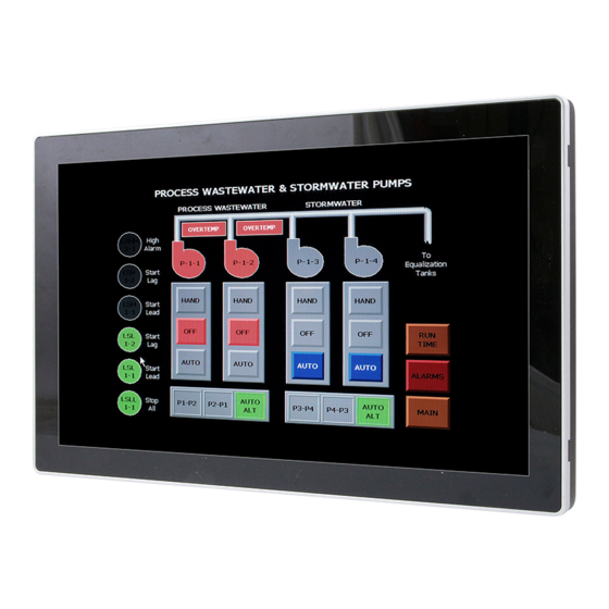
Summary of Contents for Avalue Technology BFC-10W7
- Page 1 BFC-10W7 10.1" Multifunctional Bezel Free Multi-Touch Panel Computer Quick Reference Guide Ed –05 September 2013 Copyright Notice Copyright 2013 Avalue Technology Inc., ALL RIGHTS RESERVED. Part No. E201710W7A2R...
-
Page 2: Getting Started
Place all electronic components in a static-dissipative surface or static-shielded bag when they are not in the chassis. 1.2 Packing List 1 x BFC-10W7 10.1" Multifunctional Bezel Free Multi-Touch Panel Computer 1 x DVD-ROM contains the followings: ... - Page 3 1 x RS232, 1x RS232/422/485 (selected by jumper) Ethernet 2 x RJ-45 (Dual Intel 82574L Gigabit Ethernet) 1 x HDMI & 1 x VGA Audio port 1 x Mic in 3 x USB Speaker 2 x 2W (or optional Line out x 1) BFC-10W7 Quick Reference Guide...
- Page 4 251.94mm x 154.5mm x 66.05mm (w/ HDD) Reliability EMI Test CE/FCC Class B Dust and Rain Test Front side IP65 Operating Temperature 0°C ~ 40°C Operating Humidity 0%~90% relative humidity, non-condensing Storage Temperature -10°C ~ 60°C 4 BFC-10W7 Quick Reference Guide...
- Page 5 Quick Reference Guide 1.4 System Overview 1.4.1 Front & Top View 1.4.2 Rear View Connectors Label Function Note COM1~2 Serial port connector1~2 DB-9 male connector HDMI HDMI connector VGA connector HDD Indicator BFC-10W7 Quick Reference Guide...
- Page 6 BFC-10W7 RJ-45 Ethernet LINE OUT Line-out audio jack (optional) System power switch Power USB connector Power Indicator DC-IN DC power-in connector Microphone-in audio jack MIC IN 6 BFC-10W7 Quick Reference Guide...
- Page 7 Quick Reference Guide 2. Hardware Configuration For advanced information, please refer to: 1- BFC-10W7 Quick Reference Guide or User’s Manual 2- ECM-CDV included in this manual. Note: If you need more information, please visit our website: http://www.avalue.com.tw BFC-10W7 Quick Reference Guide...
- Page 8 External Serial Port 1 connector (COM1) Signal Signal DCDA# RxDA TxDA DTRA# DSRA# RTSA# CTSA# RIA# 2.1.2 External Serial Port 2 connector (COM2) Signal PIN PIN Signal DCDB# RxDB TxDB DTRB# DSRB# RTSB# CTSB# RIB# 8 BFC-10W7 Quick Reference Guide...
- Page 9 Quick Reference Guide 2.1.3 VGA connector (VGA) PIN Signal PIN Signal PIN Signal DATA 13 HSYNC VSYNC BFC-10W7 Quick Reference Guide...
- Page 10 BFC-10W7 2.2 Installing Memory (BFC-10W7) Step 1. Remove the 8 screws to disassemble your system back cover. Step 2. Remove the 3 screws to disassemble your panel pc bezel. 10 BFC-10W7 Quick Reference Guide...
- Page 11 Quick Reference Guide Step 3. Insert DDR3 SO-DIMM memory into the memory socket. BFC-10W7 Quick Reference Guide 11...
- Page 12 BFC-10W7 2.3 Installing PCIE device (BFC-10W7) Step1. Remove the 8 screws to disassemble your system back cover. Please install mini PCIe device, and fasten with 2 screws Step2. 12 BFC-10W7 Quick Reference Guide...


Need help?
Do you have a question about the BFC-10W7 and is the answer not in the manual?
Questions and answers