Table of Contents
Advertisement
SAFETY NOTICE:
If this appliance is not properly installed, a house
fire may result. For your safety, follow the
installation directions. Contact local building or
fire officials about restrictions and installation
inspection requirements in your area.
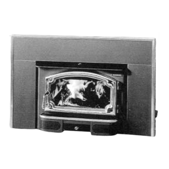
Freedom Fireplace Insert
10850 117th Place N.E. Kirkland, WA 98033
Part # 93508020
$10.00
Freedom
Owner's
Manual
- May, 2001 -
¥ Masonry
Fireplace Insert
Listed
Advertisement
Table of Contents

Related Manuals for Lopi Freedom


Summary of Contents for Lopi Freedom
-
Page 1: Safety Notice
For your safety, follow the installation directions. Contact local building or fire officials about restrictions and installation inspection requirements in your area. Freedom Fireplace Insert Listed 10850 117th Place N.E. Kirkland, WA 98033 Part # 93508020 $10.00... -
Page 3: Introduction And Important Information
Freedom you have joined the growing ranks of concerned individuals whose selection of an energy system reflects both a concern for the environment and aesthetics. The Lopi Freedom is one of the finest appliances the world over. This manual will explain the installation, operation, and maintenance of this appliance. -
Page 4: Safety Precautions
AFETY RECAUTIONS ¥ The viewing door must be ¥ Gasoline or other closed and latched during flammable liquids must operation. never be used to start the fire or "Freshen Up" the ¥ Never block free airflow fire. Do not store or use through the air vents on gasoline or other this appliance. - Page 5 AFETY RECAUTIONS ONTINUED ¥ Never try to repair or ¥ Do not make any changes replace any part of this or modifications to an appliance unless existing masonry fireplace instructions are given in or chimney to install this this manual. All other appliance.
-
Page 6: Table Of Contents
ABLE OF ONTENTS Introduction and Important Information Maintaining Your Appliance Introduction and Important Information ...... 1 Maintenance Schedule..........19 Safety Precautions............. 2 Remove Ash From The Firebox (If Necessary)..19 Clean The Viewing Glass (If Necessary) ....19 Clean The Brass (If Necessary) ......... 19 Features and Specifications Check For Creosote Buildup ........ -
Page 7: Features And Specifications
EATURES AND PECIFICATIONS Installation Options: ¥ Insert into a Masonry Fireplace Features: ¥ EPA Phase II Approved ¥ Long Burn Time - Up to 12 Hours ¥ 2.9 Cubic Foot Firebox Volume ¥ 5/16" Steel Plate Construction ¥ Single, Push/Pull Operating Control ¥... -
Page 8: Insert Installation
NSERT NSTALLATION SAFETY NOTICE: If this appliance is not properly installed, a house fire may result. For your safety, follow the installation directions. Contact local building or fire officials about restrictions and installation inspection requirements in your area. ¥ Check with local building officials for any permits required for installation of this stove and notify your insurance company before proceeding with installation. -
Page 9: Insert Placement Requirements
NSERT NSTALLATION NSERT LACEMENT EQUIREMENTS (See the illustration below) ¥ The insert must be placed so that no combustibles are within, or can swing within (e.g. drapes, doors), 36" of the front of the insert ¥ Insert and hearth must be installed on a level, secure floor ¥... -
Page 10: Masonry Fireplace Requirements
NSERT NSTALLATION ASONRY IREPLACE EQUIREMENTS ¥ Chimney must have a clay tile liner or a stainless steel liner (positive connection) ¥ Entire fireplace, including chimney, must be clean and undamaged. Any damage must be repaired prior to installation of the insert ¥... -
Page 11: Block-Off Plate Installation
NSERT NSTALLATION LOCK LATE NSTALLATION Whenever this appliance is installed with a direct connection a block-off plate, or other non-combustible seal-off device (e.g. damper adapter), will need to be installed. This device is used to seal the chimney, insuring no smoke enters the home and providing the chimney system with a seal to provide greater draft. -
Page 12: Insert With Positive Connection
NSERT NSTALLATION NSERT WITH Install a non-combustible Cap (prevents water OSITIVE cover plate to prevent water from entering) from entering the chimney ONNECTION NOTE: This installation may be NOTE: used with a masonry fireplace Flue Liner only. The requirements in the Most factory- The liner must be section "Masonry Fireplace... -
Page 13: Insert With Face Seal Connection
NSERT NSTALLATION NSERT WITH NOTE: This installation may be used with a masonry fireplace only. The requirements in the ONNECTION section "Masonry Fireplace NOTE: It is Requirements" must be fulfilled recommended your prior to installation. NOTE: chimney have a Face seal minimum 28 and a Flue Liner maximum of 144... -
Page 14: Operating Your Appliance
PERATING PPLIANCE SAFETY NOTICE: If this appliance is improperly operated , a house fire may result. For your safety, read the directions below and the Safety Precautions listed on pages 2 and 3 prior to operating this appliance. ¥ If you have any questions regarding the operation of this appliance, contact your dealer. Building a fire in disregard of the information provided in this section can cause permanent damage to your appliance and void your warranty. -
Page 15: Bypass Control
PERATING PPLIANCE ONTINUED Bypass Control The bypass control is centered along the top of the appliance and is operated by pushing or pulling the control in or out. When the control is completely pulled out, the bypass allows the smoke to go directly up the flue, creating more draft for starting the appliance or reloading. -
Page 16: How To Reload Your Appliance
PERATING PPLIANCE ONTINUED How to Reload Your Appliance When reloading your appliance, you can avoid smoke entering the room by following the steps below: 1. Push the air control all the way in so the fire starts to burn quickly, helping draft. 2. -
Page 17: How To Obtain An Overnight Burn
PERATING PPLIANCE ONTINUED How to Obtain an Overnight Burn An overnight burn of 10 hours may be obtained with a small amount of coals left over in the morning if the right steps are taken. 1. Establish a hot fire. 2. -
Page 18: Blower Operation
PERATING PPLIANCE ONTINUED LOWER PERATION The optional blower assists the convection chamber in distributing heat to your home. The directions below detail operation. Automatic Control The optional blower has a temperature-sensing device to automatically enable the blower once the appliance reaches a hot temperature. It also shuts the blower off once the appliance has cooled. When to turn the blower on The blower should be left on the off position for the first 30 minutes of starting the appliance. -
Page 19: A Word About Wood
PERATING PPLIANCE ONTINUED ORD ABOUT This appliance is designed to burn natural cord wood with high efficiencies and low emissions. With properly dried wood, you will fully realize the heating and clean-burning potential of our high- technology appliance. With poor wood, this high-technology appliance will become much less efficient and produce more emissions. - Page 20 PERATING PPLIANCE ONTINUED ORD ABOUT ONTINUED Sheet Metal Roofing 2x4 Purlins 2x6x12 Rafter Constructing a Wood Shed 2x8x8' Girder The drawing to the right details the 4x4x2 Posts Spaced 8' Apart construction of an inexpensive wood shed Siding and Girts (Optional) that will promote drying, increasing the heat output from your wood.
-
Page 21: Maintaining Your Appliance
AINTAINING PPLIANCE AINTENANCE CHEDULE Your appliance requires periodic maintenance to work correctly. The steps involved with maintenance are usually quick and easy. Look through this maintenance schedule and plan accordingly. WARNING: Failure to properly maintain and inspect your appliance may reduce the performance and life of the appliance, void your warranty, and create a fire hazard. -
Page 22: Door And Glass Inspection
AINTAINING PPLIANCE ONTINUED LASS NSPECTION The door must seal air-tight for the appliance to work correctly. Check the two items below and follow the appropriate remedy to fix any problems. ¥ Check the door cam operation. When closed, the door cam should pull the door against the face of the appliance, but not be so tight as to not allow the handle to point downwards. -
Page 23: Replacing The Door Gasket
AINTAINING PPLIANCE ONTINUED Replacing the Door Gasket Remove the door by opening it and lifting it off the hinges. Remove the old gasket by stripping it away with a screwdriver or other tool (see the illustration below). Apply a line of gasket cement (available from your dealer) in the groove that follows the perimeter of the door. -
Page 24: Touch-Up Paint
AINTAINING PPLIANCE ONTINUED OUCH AINT Included with the owner's pack of this appliance is a can of Stove-BriteÒ paint. To touch up nicks or dulled paint, apply the paint while the appliance is cool. Use 120 grit sandpaper (clean with water and dry with a piece of cloth) if the surface requires smoothing. -
Page 25: Firebrick Removal And Replacement Inst
AINTAINING PPLIANCE ONTINUED Firebrick Removal and Replacement Instructions With the appliance cool, remove all ash from the firebox. Only the firebrick that is damaged must be replaced. If the damaged firebrick is on the floor, it can be replaced by simply removing the firebrick in front of it. - Page 26 AINTAINING PPLIANCE ONTINUED Baffle Removal and Replacement Instructions (continued) All of the baffle components are removable to facilitate easy cleaning and repairs. Make sure the appliance is cool before removing any of the components. See the instructions on the following page for removing the secondary air tubes.
-
Page 27: Secondary Air Tube Replacement Instructions
AINTAINING PPLIANCE ONTINUED Secondary Air Tube Replacement Instructions NOTE: Each secondary air tube is a different length Ð specify the correct tube when replacing. Secondary Air Pry out both pins on the secondary REMOVING THE Tube Sleeve air tube sleeve (use a screwdriver). SECONDARY AIR TUBES Follow the directions to the right. -
Page 28: Troubleshooting
ROUBLESHOOTING Problem: Possible Cause: Remedy: Smoke Spills From ¥ Door was opened before the air Pull the air control all the way out a few seconds before Door When control was pushed in opening the door. Loading ¥ Door was opened before the Pull the bypass all the way out before opening the door bypass was pulled out (see "Bypass Control"... -
Page 29: Warranty
ARRANTY To register your TRAVIS INDUSTRIES, INC. 7 Year Warranty, complete the enclosed warranty card and mail it within ten (10) days of the appliance purchase date to: TRAVIS INDUSTRIES, INC., 10850 117th Place N.E., Kirkland, Washington 98033. TRAVIS INDUSTRIES, INC. warrants this appliance (appliance is defined as the equipment manufactured by Travis Industries, Inc.) to be defect-free in material and workmanship to the original purchaser from the date of purchase as follows: Years 1 &... -
Page 30: Listing Information
RODUCT ISTING NFORMATION The data on the label below matches the data on the label attached to the side of your insert. -
Page 31: Optional Equipment
LUSH # 99900151) This kit allows the Freedom insert to be installed with more of the unit inside the fireplace (flush) rather than extended onto the hearth. The flush kit must be installed prior to installing the surround panels or placing the insert. -
Page 32: Surround Panel Installation
PTIONAL QUIPMENT ONTINUED URROUND ANEL NSTALLATION EE TABLE BELOW FOR PART NUMBER Surround panel size is determined by the type of installation and the size of the fireplace opening. Direct and positive connections do not require insulation or panels that overlap the fireplace opening (panels that overlap the fireplace opening are usually more attractive). -
Page 33: Insulation Installation
PTIONAL QUIPMENT ONTINUED URROUND ANEL NSTALLATION ONTINUED Top Panel The joggle clips on the top panel slide over the offset portion on top of the side panels and over the mounting angle. Attach the mounting angle to the top of the insert with the two thread-cutting screws (10-24 1/2"... -
Page 34: Front Blower Installation
PTIONAL QUIPMENT ONTINUED URROUND ANEL NSTALLATION ONTINUED 3. Some kits include double-back tape. For those kits, follow the instructions below. Attach a square of double-back tape to each of the bottom corners of the surround panels before installing the trim. This will keep the panels from flaring at the bottom. Surround Surround Panel Panel... -
Page 35: Flue Adapter Installation
PTIONAL QUIPMENT ONTINUED DAPTER NSTALLATION 98900120) ART NUMBER The flue adapter has a built in flue collar with pre-drilled holes designed to make flue attachment easier. It may also be used to adjust the position of the flue exit, up to 2 1/2" forward or 1 5/8" back. 1. -
Page 36: Index
NDEX Adjusting the Heat Output ..........14 Hearth Requirements ........... 7 Air Control Settings ............12 Heating Capacity............5 Ash Removal..............19 Insert Placement Requirements ........7 Baffle (removal and replacement) ........ 23 Insert Size Requirements ..........7 Block-Off Plate Installation ........... 9 Insulation Installation (for panels) ........
Need help?
Do you have a question about the Freedom and is the answer not in the manual?
Questions and answers