Lopi Revere Owner's Manual
Fireplace insert
Hide thumbs
Also See for Lopi Revere:
- Owner's manual (36 pages) ,
- Owner's manual (34 pages) ,
- Owner's manual (32 pages)
Table of Contents
Advertisement
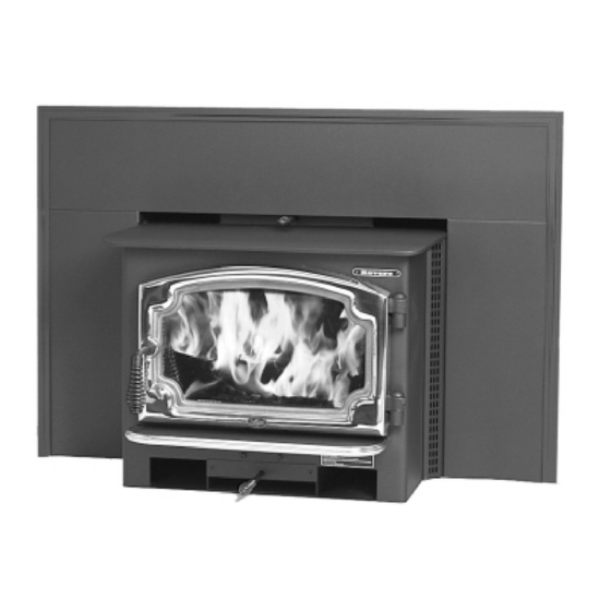
R e v e r e Fireplace Insert
SAFETY NOTICE:
If this appliance is not properly installed, a house fire may
result. For your safety, follow the installation directions.
Contact local building or fire officials about restrictions and
installation inspection requirements in your area.
Copyright 2007, T.I.
$10.00
100-01165
4040806
Owner's
Manual
• Masonry Fireplace
Insert
• Zero-Clearance
(Metal) Fireplace
Insert
Save these instructions
for future reference
Listed
Tested to: U.L. 1482
Advertisement
Table of Contents

Subscribe to Our Youtube Channel
Related Manuals for Lopi Lopi Revere


Summary of Contents for Lopi Lopi Revere
-
Page 1: Safety Notice
R e v e r e Fireplace Insert Owner's Manual • Masonry Fireplace Insert • Zero-Clearance (Metal) Fireplace Insert Save these instructions for future reference SAFETY NOTICE: If this appliance is not properly installed, a house fire may result. For your safety, follow the installation directions. Contact local building or fire officials about restrictions and installation inspection requirements in your area. -
Page 2: Introduction
Introduction Introduction We welcome you as a new owner of a Lopi Revere wood-burning fireplace insert. In purchasing a Lopi Revere you have joined the growing ranks of concerned individuals whose selection of an energy system reflects both a concern for the environment and aesthetics. The Lopi Revere is one of the finest appliances the world over. -
Page 3: Table Of Contents
Adjusting the Burn Rate ........17 Ash Removal ............ 17 Index ...............34 Optional Blower Operation........18 Re-Loading the Stove ......... 18 Overnight Burn..........18 Normal Operating Sounds ........18 Hints for Burning..........19 Selecting Wood ..........19 Troubleshooting ..........20 © Travis Industries 100-01165 4040806... -
Page 4: Safety Precautions
(UL 103 HT) Clay cause a house fire. residential type chimney or an Liner Do not connect this appliance to approved masonry chimney with any chimney serving another a standard clay tile, or stainless appliance. steel liner. © Travis Industries 100-01165 4040806... - Page 5 Avoid placing wood against the glass when loading. Do not slam the door or strike the glass. Do not throw this manual away. Travis Industries, Inc. grants This manual has important no warranty, implied or This operating and maintenance...
-
Page 6: Features & Specifications
13-1/8" - ZC (metal) fireplaces require 1" clearance to the rear. 21-3/8" 24-1/4" 10" (does not include required hearth) Figure 1 Emissions: 1.9 Grams Per Hour (EPA Phase II Approved) – Tests conducted by E.E.S.P.C. © Travis Industries 100-01165 4040806... -
Page 7: Planning The Installation
Planning The Installation We suggest that you have an authorized Travis Industries dealer install your fireplace insert. If you install the fireplace insert yourself, your authorized dealer should review your installation plans. Check with local building officials for any permits required for installation of this fireplace insert and notify your insurance company before proceeding with installation. -
Page 8: Fireplace Requirements
47-1/4" 30-3/4" with mantel shield 39-1/4" Mantel Height 49-1/4" 42-3/4" with mantel shield 41-1/4" * This is the distance the insert protrudes from the fireplace opening plus the required 16" of hearth extension. Figure 2 © Travis Industries 100-01165 4040806... -
Page 9: Insert Placement Requirements
Entire fireplace, including chimney, must be clean and undamaged. Any damage must be repaired prior to installation of the insert • Chimney height: 15' minimum; 33' maximum. • Entire fireplace, including chimney, must meet local building requirements © Travis Industries 100-01165 4040806... -
Page 10: Zero-Clearance (Metal) Fireplace Requirements
This appliance relies upon natural draft to operate. External forces, such as wind, barometric pressure, topography, or factors of the home (negative pressure from exhaust fans, chimneys, air infiltration, etc.), may adversely affect draft. Travis Industries can not be responsible for external forces leading to less than optimal performance. -
Page 11: Block-Off Plate Installation
Measurement "C" See the dimensions to determine the location of the Measurement "B" center of the Firebox flue. See the dimensions to determine the location of the center of the flue. Figure 6 © Travis Industries 100-01165 4040806... -
Page 12: Insert With Positive Connection
Insulated Clean-Out adapter (see "Block-off Plate Installation" on page 11). Remove damper Surround Panels or wire it open See the section "Insert Placement Requirements" for Block-off plate or minimum clearances damper adapter and hearth required. © Travis Industries 100-01165 4040806... -
Page 13: Insert With Direct Connection (Z.c. Fireplace)
Surround Panels with insulation (see "Surround Panels" installation instructions in the back of the manual) Airtight Insulated Clean-Out See the section "Insert Placement Requirements" for minimum clearances and hearth required. Remove damper or wire it open © Travis Industries 100-01165 4040806... -
Page 14: Operating Your Appliance Safety Notice
The door becomes hot during use. Use a glove to open the door if the handle is hot. To prevent smoke from entering the room, open the bypass before opening the door (see following page for directions). You can also open the door a small amount and let air enter the firebox. © Travis Industries 100-01165 4040806... -
Page 15: Bypass Operation
When starting or re-loading, pull the bypass out. • During normal operation, push the bypass in. Bypass Pulled Out Used for starting and re-loading Use the included pull tool to operate the bypass rod Bypass Pushed In Used for normal operation © Travis Industries 100-01165 4040806... -
Page 16: Starting A Fire
This should start the chimney drafting (this eliminates "cold air blockage"). Use plenty of kindling to ensure the stove reaches a proper temperature. Once the kindling is burning rapidly, place a few larger pieces of wood onto the fire. © Travis Industries 100-01165 4040806... -
Page 17: Adjusting The Burn Rate
If the ashes are disposed of by burial in soil or otherwise locally ASHES dispersed, they should be retained in the closed container until all cinders have thoroughly cooled. © Travis Industries 100-01165 4040806... -
Page 18: Optional Blower Operation
- this is normal. Blower Sounds: The blower will make a slight "humm" as it pushes air through the stove. Hint: Make sure the leveling bolts on legs are extended - preventing the hearth from amplifying any vibrations. © Travis Industries 100-01165 4040806... -
Page 19: Hints For Burning
Wood Cutting and Storage Cut wood to length and Store the wood off the ground in a chop into quarters. covered area. Allow for airflow Air Flow around the wood to dry the wood. Air Flow Air Flow © Travis Industries 100-01165 4040806... -
Page 20: Troubleshooting
See the section "Door and Glass Inspection" on page 22 for details. • Check the ash bed for coals. Often, coals are still glowing under a slight bed of flyash. By raking these into a pile you can re-start your stove quickly. © Travis Industries 100-01165 4040806... -
Page 21: Maintaining Your Appliance
The ash acts as a light abrasive. The glass will develop a very slight haze over time. This is normal and will not affect viewing of the fire. © Travis Industries 100-01165 4040806... -
Page 22: Monthly Maintenance (While Appliance Is In Use)
If you are not certain of creosote inspection, contact your dealer or local chimney sweep for a full inspection. Excess creosote buildup may cause a chimney fire, that may result in property damage, injury, or death. © Travis Industries 100-01165 4040806... -
Page 23: Yearly Maintenance
Slight scaling or rusting of the metal is normal. Make sure the push pins hold the air tubes in place. Floor and Wall Firebricks - replace any severely damaged firebrick along the side or floor of the firebox. © Travis Industries 100-01165 4040806... -
Page 24: Door Parts
You may need to open and close the door repeatedly to get the gasket to seat fully. Replacing the Door Handle See the illustration above for a component list (see pg. 24 for details on adjusting the door). © Travis Industries 100-01165 4040806... -
Page 25: Firebox Parts
Do not pry firebrick - they chip and crack easily. Remove the floor firebricks first. The side firebrick are removed later because they are pinned in place by the floor firebrick. Clean the firebox prior to replacing the firebrick. © Travis Industries 100-01165 4040806... -
Page 26: Baffle Removal & Replacement
Air Tube Removal & Replacement Air Tube Collar Air Tube Remove the left pin on the air tube collar Roll Pin Slide the air tube to the left, swing it down and remove from the firebox. © Travis Industries 100-01165 4040806... -
Page 27: Warranty Warranty
16. If for any reason any section of this warranty is declared invalid, the balance of the warranty remains in effect and all other clauses shall remain in effect. 17. This 7 year warranty is the only warranty supplied by Travis Industries, Inc., the manufacturer of the appliance. All other warranties, whether express or implied, are hereby expressly disclaimed and purchaser’s recourse is expressly limited to the warranties set forth herein. -
Page 28: Listing Label
10850 117th Pl. N.E. Kirkland, WA 98033 U.S. ENVIRONMENTAL PROTECTION AGENCY Certified to comply with July 1990 particulate emission standards. Date of Manufacture 2001 2002 2003 Jan. Feb. Mar. Apr. May June July Aug. Sept. Oct. Nov. Dec. 0234 © Travis Industries 100-01165 4040806... -
Page 29: Optional Equipment
Insert the retainer into the door shell following the directions below. Note how the door shell is guided into place Door Retainer Door Shell The indent on the door retainer slides into the clip on the door shell (on both sides). © Travis Industries 100-01165 4040806... - Page 30 Attach the ashlip trim following the directions below. 9/16" Wrench 1/16” Hex Wrench Slide the ashlip trim into place then tighten the three set screws on the bottom of the ashlip to secure. © Travis Industries 100-01165 4040806...
-
Page 31: Surround Panels
Then insert the studs through the holes on the side of the convection channel. Attach the nuts (included with the insert) to secure the panels. © Travis Industries 100-01165 4040806... - Page 32 2. Push the insert into the fireplace, allowing the insulation to form a seal between the panels and the fireplace. Use a screwdriver to tuck any exposed insulation behind the panels. © Travis Industries 100-01165 4040806...
-
Page 33: Front Blower (Part # 99000133)
Control Box Use a 3/8" nutdriver to replace the two screws and hold the front blower to the appliance. 2. Plug the power cord running from the control box into a grounded 110 volt electrical outlet. © Travis Industries 100-01165 4040806... -
Page 34: Index
Glass Replacement ........24 Hearth (Floor Protection).........9 Heating Specifications ........6 Hints for Burning ...........19 Installation (planning) ........7 Installation Options ........6 Installation ...........7 Listing Label..........28 Maintenance ..........21 Masonry Fireplace .........9 Monthly Maintenance ........22 Noise (Normal Operating Sounds) ....18 © Travis Industries 100-01165 4040806...
Need help?
Do you have a question about the Lopi Revere and is the answer not in the manual?
Questions and answers