Table of Contents
Advertisement
Quick Links
WARNING:
If the information in these instructions is not followed exactly, a fire or explosion may result
causing property damage, personal injury or loss of life.
DO NOT PLACE ARTICLES ON OR AGAINST THIS APPLIANCE.
DO NOT USE OR STORE FLAMMABLE MATERIALS NEAR THIS APPLIANCE.
DO NOT SPRAY AEROSOLS IN THE VICINITY OF THIS APPLIANCE WHILE IT IS IN OPERATION.
DO NOT MODIFY THIS APPLIANCE.
-
Do not store or use gasoline or other flammable vapors and liquids in the vicinity of this or any other appliance.
WHAT TO DO IF YOU SMELL GAS
• Do not try to light any appliance.
• Do not touch any electrical switch; do not use any phone in your building.
• Immediately call gas supplier from a neighbor's phone. Follow the gas supplier's instructions.
• If you cannot reach your gas supplier, call the fire department.
-
Installation and service must be performed by a qualified installer, service agency or the gas supplier.
This appliance may be installed in
an aftermarket permanently
located, manufactured home (USA
only) or mobile home, where not
prohibited by local codes.
This appliance is only for use
with the type(s) of gas indicated
on the rating plate. A conversion
kit is supplied with the appliance.
Installation Manual
Installer:
After installation give this manual to the home-
owner and explain operation of this heater.
Copyright 2020, T.I.
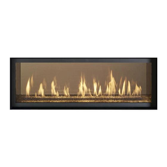
ProBuilder 72 Linear
$10.00
100-01478
GSB2/GSR2
• Direct Vent Fireplace
• Natural Gas or Propane
• Vent Horizontally or Vertically
• Standard Residential
• Mobile Home Approved
Listed by
AS/NZS 5263.1.3
GMK10166
IAPMO-R&T OCEANA
Dragon Wholesaling Pty. Ltd.
Unit 4, 16 Lexington Drive
Bella Vista NSW
11/9/20
Australia 2153
Advertisement
Table of Contents

Subscribe to Our Youtube Channel
Related Manuals for Lopi Pro Builder 72 Linear GSB2


Summary of Contents for Lopi Pro Builder 72 Linear GSB2
- Page 1 ProBuilder 72 Linear GSB2/GSR2 • Direct Vent Fireplace • Natural Gas or Propane • Vent Horizontally or Vertically • Standard Residential • Mobile Home Approved Listed by AS/NZS 5263.1.3 GMK10166 IAPMO-R&T OCEANA WARNING: If the information in these instructions is not followed exactly, a fire or explosion may result causing property damage, personal injury or loss of life.
-
Page 2: Overview
Introduction Overview This manual details the installation requirements for the Pro Builder 72 Linear GSB2 or GSR2 fireplace. For operating and maintenance instructions, refer to the Pro Builder 72 Linear Owner's Manual. © Travis Industries 11/9/20 - 1478 PB 72 GSB2/GSR2 Aust. -
Page 3: Table Of Contents
Table of Contents THICK FACING GUIDE SIZE ......... 35 Overview ..............2 Screen Assembly Mounts ..........36 Do Not Drill or Screw Zone ..........37 Installation Options ..........6 Mantel Requirements ..........38 Heating Specifications ..........6 ... - Page 4 Safety Precautions Safety Warnings Failure to follow all of the requirements may result in property damage, bodily injury, or even death. Young children should be carefully supervised when they are in the same room as the appliance. Toddlers, young children and others may be susceptible to accidental contact burns.
- Page 5 Safety Precautions Safety Warnings (continued) Because this heater can be controlled by a thermostat there is a possibility of the heater turning on and igniting any items placed on or near the appliance. Light the heater using the built-in igniter. Do not use matches or any other external device to light your heater. ...
-
Page 6: Installation Options
Features and Specifications Installation Options Residential or Mobile Home Internal or External Chase Straight or Corner Placement Bedroom Approved Raised or Floor Placement Heating Specifications Natural Gas Propane Approximate Heating Capacity (in square meters)* Up to 209 Up to 209 Maximum Input Per Hour (MJ/H) 43.8... -
Page 7: Packing List
Installation (for qualified installers only) Packing List LP (Propane) Conversion Kit - Burner Orifices (2)-(#54), Pilot Orifice (0.14 LP), LP Regulator Thimble (2-Piece Assembly) Pipe Shield, Header Shield (shipped attached to top of fireplace) Additional Items Required ... -
Page 8: Fireplace Placement Requirements
Installation (for qualified installers only) Fireplace Placement Requirements Fireplace must be installed on a level surface capable of supporting the fireplace and vent Fireplace must be placed directly on wood or non-combustible surface (not on linoleum or carpet) ... -
Page 9: Televisions Placed Above The Fireplace
Installation (for qualified installers only) Televisions Placed Above the Fireplace The following section gives guidelines to place a television above the fireplace. IMPORTANT NOTE REGARDING TELEVISIONS AND THIS FIREPLACE Most television manufacturers instruct the homeowner not to place the television above a heat source like this fireplace. -
Page 10: Minimum Framing Dimensions
Installation (for qualified installers only) Minimum Framing Dimensions Min. Framing - Without CoolSmart TV kit WARNING When using a CoolSmart TV kit, see section: “CoolSmart TV - Framing the Chase” on page 63. 68" 1727mm Max. 3" 77mm 43" 1092mm 77-1/8"... -
Page 11: Standoff Assembly
Installation (for qualified installers only) Standoff Assembly The side and rear standoffs must be assembled prior to placing the fireplace into position. These standoffs, when properly constructed, provide a guide for the required 1/2" clearance. NOTE: The rear standoffs are bent around the rear corners of the fireplace as shown below to the right. -
Page 12: Minimum Vent "Bump Out" Application
Installation (for qualified installers only) Minimum Vent “Bump Out” application Min. 11” (280mm)* Min. 6” (153mm)* 8” (204mm) Certain configurations Vent may require vertical vent Centerline sections (see “Vent Requirements” for details. SIDE OF FIREPLACE Base of Fireplace * See “Vent Termination Requirements”... -
Page 13: Nailing Brackets
Installation (for qualified installers only) Nailing Brackets The fireplace has nailing brackets on both sides. Secure the fireplace to the framing with the nailing brackets. NOTE: Make sure the fireplace is square and plumb when placed in the framing. Measured corner-to- corner the fireplace should be square. -
Page 14: Standard Vs. Extended Position
Installation (for qualified installers only) Standard vs. Extended Position There are two positions that the standoff/heat shield assembly can be installed. The standoffs are shipped in the standard (forward) position. If the unit is installed in the standard position no modification is needed. ... -
Page 15: Header And Pipe Shield Installation
Installation (for qualified installers only) Header and Pipe Shield Installation The header and pipe shield must be installed as shown below. NOTE: The header and pipe shields may be installed after the fireplace is in place and vent attached (this allows for the fireplace to fit into the framing underneath the header and for the vent to be installed more easily). - Page 16 Installation (for qualified installers only) Line up the holes on the pipe shield tabs with the holes on the top of the fireplace. Use the screws that secured the shield during shipping to attach the pipe shield to the top of the fireplace. ©...
- Page 17 Installation (for qualified installers only) Remove the (4) screws from each of the (2) header shields (keep the screws for reinstallation). Turn each of the shields over endwise and secure them back into place using the screws you just removed. The bent edge of the shields should be facing upward and toward the back of the fireplace (see illustration below).
- Page 18 Installation (for qualified installers only) When finished the fireplace should be configured like the picture below. © Travis Industries 11/9/20 - 1478 PB 72 GSB2/GSR2 Aust.
-
Page 19: Corner Installations
Installation (for qualified installers only) Corner Installations A typical 45° installation uses the framing dimensions shown in the illustration below (NOTE: all clearances still apply). (a) Corner to Wall (minimum) 76-7/16” (1942mm) (b) Corner to Center of Flue (typical) 31-1/4” (794mm) Minimum 1/2"... -
Page 20: Removing The Front Panel
Installation (for qualified installers only) Removing the Front Panel The front cover may be removed to access the components. This is required when relocating the electrical or gas inlet location. To remove the front cover 1/4" Nutdriver/Wrench (a) Remove the center wingnuts. (b) Loosen the two outer screws. -
Page 21: Gas Line Requirements
Installation (for qualified installers only) Gas Line Requirements The gas line must be installed in accordance with all local codes and the requirements listed below. In the absence of local codes, follow ANSI 223.1 in US/Canada or AS/NZS 5601.1 in Australia. ... -
Page 22: Gas Line Location
Installation (for qualified installers only) Gas Line Location NOTE FOR RIGID PIPE: When using rigid pipe, you may wish to disconnect the shutoff valve from the fireplace and route the pipe through the fireplace wall. First, disconnect the gas line from the shutoff valve. Disconnect the shutoff valve from the cover plate (4 screws outside fireplace). -
Page 23: Electrical Connection
Installation (for qualified installers only) Electrical Connection The electrical line to the grounded receptacle inside the fireplace must be installed by a qualified installer and must meet all local codes. Make sure the household breaker is shut off prior to working on any electrical lines. ... -
Page 24: Optional Wall Switch Or Thermostat Installation (Gsb2 Only)
Installation (for qualified installers only) Optional Wall Switch or Thermostat Installation (GSB2 only) Do not connect 240 VAC to the gas control valve or wiring system of this fireplace. The switch and wiring must be installed by a qualified installer. This fireplace includes an optional wall switch (with wire) to OPTIONAL WALL SWITCH operate the fireplace burner without accessing the internal... -
Page 25: Vent Requirements
Installation (for qualified installers only) Vent Requirements The gas appliance and vent system must be vented directly to the outside of the building, and never be attached to a chimney serving a separate solid fuel or gas-burning appliance. Each direct vent gas appliance must use its own separate vent system. -
Page 26: Vent Installation
Installation (for qualified installers only) Vent Installation Slide the vent sections together and turn 1/4 turn until the sections lock in place. Screws are not required to secure the vent. However, three screws may be used to secure vent sections together if desired. -
Page 27: Diffuser
Installation (for qualified installers only) Diffuser A diffuser is built into the appliance to adjust the flow rate of exhaust gases. Depending upon the vent configuration, you may be required to adjust the diffuser to the open position (see illustration below). The charts for vent configurations detail the correct diffuser position. -
Page 28: Minimum Vent Configuration
Installation (for qualified installers only) Minimum Vent Configuration Use 5x8” Diameter Coaxial Vent NOTE: Use the included thimble assembly whenever passing through a wall. (use on front and back of wall penetration). See picture below. The termination must fall within the shaded area shown in the chart. Use the indicated restrictor positions. -
Page 29: Vent Configuration: Vertical Termination
Installation (for qualified installers only) Vent Configuration: Vertical Termination Vent configurations 20’ or above (from the base of the fireplace) use 6-5/8” dia. vent. Connect a 8” to 6-5/8” reducer directly to the fireplace (98900165). NOTE: The included thimble assembly is not required and may be discarded. ... -
Page 30: Vent Configuration: Horizontal Termination With Vertical Rise
Installation (for qualified installers only) Vent Configuration: Horizontal Termination with Vertical Rise Vent configurations 20’ or above (from the base of the fireplace) use 6-5/8” dia. vent. Connect a 8” to 6-5/8” reducer directly to the fireplace (98900165). NOTE: For this configuration the included thimble assembly is not required and may be discarded. -
Page 31: Termination Requirements
Installation (for qualified installers only) Termination Requirements Vent Terminations Must Comply with AS/NZS 5601.1 Venting terminals shall not be recessed into a wall or siding. Minimum 9" (229mm) clearance from any door or window Roof Minimum 12" (305mm) above any grade, veranda, porch, deck or balcony Surface Minimum 1"... -
Page 32: Hearth Requirements
Installation (for qualified installers only) Hearth Requirements If installed near carpet or other combustible flooring, the fireplace must be raised so the base of the unit is above the carpet surface or flooring material. If the heater is installed at floor level, we recommend a non-combustible hearth to protect the flooring surface from discoloration or other negative impact from the heater. -
Page 33: Facing Requirements
Installation (for qualified installers only) Facing Requirements Non-combustible facing must extend from the base of the fireplace to 35-1/2”(902mm) above the base of the fireplace (see illustration below for details). Non-combustible facing must extend the entire width of the unit to the framing opening on both sides. ... -
Page 34: Standard Vs. Extended Position
Installation (for qualified installers only) Standard vs. Extended Position The nailing brackets on the side of the fireplace may be placed in the standard or extended position to best suit the facing being used (the header shield is also moved). Most installations use the standard nailing bracket position. -
Page 35: Facing Thicker Than 1-1/2" (38Mm)
Installation (for qualified installers only) Facing Thicker than 1-1/2” (38mm) If using thick facing, make sure to leave the thick facing guide in place. Make sure to leave the screen assembly in the stock (fully in) position. You may leave the screen assembly in place while installing thick facing. You may wish to protect it with plastic (or other suitable material) to repel debris. - Page 36 Installation (for qualified installers only) Screen Assembly Mounts The screen assembly mounts (located on outer front edges of the fireplace) are adjustable to allow the screen assembly to be positioned 1/2" to 1-/12” from the front of the fireplace. This allows facing to tuck under the screen assembly.
-
Page 37: Do Not Drill Or Screw Zone
Installation (for qualified installers only) Do Not Drill or Screw Zone When using screws to secure tile-board or other non-combustible to the front of the fireplace, make sure to avoid the area on the front of the fireplace that is painted with the “DO NOT DRILL” shading. Make sure screws penetrate no more than ½”... -
Page 38: Mantel Requirements
Installation (for qualified installers only) Mantel Requirements Use the table below to determine the maximum mantel depth allowed. The mantel depth (measured from the non-combustible facing) must fall within the shaded portion of the table. Any material above the fireplace that protrudes more than 3/4” (19mm) from the non-combustible facing is considered a mantel and must meet the mantel requirements. -
Page 39: Use Of A Non-Combustible Mantel Below Listed Mantel Clearances
Installation (for qualified installers only) Use of a Non-Combustible Mantel Below Listed Mantel Clearances Each gas fireplace has a unique set of mantel requirements. If you wish to place a non- combustible mantel at a lesser height than specified in this manual, it will need to meet the following requirements: ... -
Page 40: Finalizing The Installation
Installation (for qualified installers only) Finalizing the Installation 1. Remove the glass (see page 43). NOTE: If using propane (LP) convert the appliance prior to installing the media. 2. We recommend you purge the gas line at this time (with the glass removed). This allows gas to be detected once it enters the firebox, ensuring gas does not build up. -
Page 41: Air Shutter Adjustment
Installation (for qualified installers only) Air Shutter Adjustment Let the heater burn for fifteen minutes (make sure the logs and glass are in place). The flames should be yellow with no sooting. Adjust the air shutter, if necessary, to achieve the correct looking flame. Air Shutter Adjustment Correct Not Enough Air... -
Page 42: Location Of Controls
Installation (for qualified installers only) Location of Controls There is a door on the lower portion of the screen assembly to provide access to the manual controls on the fireplace. The door is held closed by two magnets. Open the door by gently pulling outward on the upper portion of the lower trim. -
Page 43: Glass Frame Removal And Installation
Installation (for qualified installers only) Glass Frame Removal and Installation A barrier designed to reduce the risk of burns from the hot viewing glass is provided with this appliance and shall be installed for the protection of children and other at-risk individuals. If the barrier becomes damaged, the barrier shall be replaced with the manufacturer’s barrier for this appliance. - Page 44 Installation (for qualified installers only) 2. Remove the glass frame following the directions below. Open the latches holding the glass frame in place (start with the bottom) - follow the directions shown to the right. Pliers may be used Top of Firebox Latch Glass...
- Page 45 Installation (for qualified installers only) The latch can come loose from glass frame anchor. This occurs when it is turned 1/4 turn when it is disengaged. Follow the directions below to re-install the latch if it becomes loose. Hold the latch at an angle and insert it into the slot on the glass frame anchor. Latch NOTE: this slot may be at a different angle than illustrated.
-
Page 46: Barrier Screen Visual Deflector Adjustment
Installation (for qualified installers only) Barrier Screen Visual Deflector Adjustment The barrier screen assembly has an adjustable visual deflector along the lower edge. If the assembly is adjusted to accommodate thick facing material, adjust the deflector, as shown below, to block the view of the valve area. -
Page 47: Crushed Glass Installation
Installation (for qualified installers only) Crushed Glass Installation Do not allow the crushed glass to block the air slots or to become too thick (maximum 1 layer deep on the burner). Failure to properly install glass may lead to sooting and improper burning. - Page 48 Installation (for qualified installers only) Spread an even layer of crushed glass over the media tray and burner. The glass must be only 1 layer thick on the burner but can be 2 layers thick on the media tray. Make sure no glass is in the pilot area indicated in the picture below.
-
Page 49: Lp Conversion Instructions
Installation (for qualified installers only) LP Conversion Instructions WARNING This conversion kit shall be installed by a qualified service agency in accordance with the manufacturer’s instructions and all applicable codes and requirements of the authority having jurisdiction. If the information in these instructions is not followed exactly, a fire, explosion or production of carbon monoxide may result causing property damage, personal injury or loss of life. - Page 50 Installation (for qualified installers only) 3. Remove both burners. Each is held in place with 6 screws (1/4” nutdriver). 4. Use a ¼” nut driver to remove (4) screws (2 per side) securing the air shutter retainers (left and right) to the fireplace.
- Page 51 Installation (for qualified installers only) 5. Follow the directions below to replace the orifice. Remove the manifold gasket (note orientation - the larger side goes downwards). REPLACE THE GASKET AFTER INSTALLING LP ORIFICE. Use a 9/16" wrench to secure the manifold while removing the orifice 9/16"...
- Page 52 Installation (for qualified installers only) 7. Install the LP pilot orifice following the instructions below. (a) Use a 7/16” open-end wrench to remove the pilot hood. (b) Remove and discard the Natural Gas (NG) orifice. Place the LP orifice in the pilot assembly then replace the pilot hood, tightening the pilot hood until it is snug (do not over-tighten).
- Page 53 Installation (for qualified installers only) 8. Remove the regulator from the front of the gas control valve. There is an knob extension on the regulator knob that will need to be moved to the new regulator. To remove the extension pull toward you.
-
Page 54: Wall Mount Remote Thermostat Installation (Optional For Gsb2 Only)
Installation (for qualified installers only) Wall Mount Remote Thermostat installation (optional for GSB2 only) Installation If Using the Optional Blower, Install it First The optional blower should be installed before installing the remote. Remove the lower front access panel from the fireplace by reaching in behind it and loosening the two wing nuts and (1) ¼”... - Page 55 Installation (for qualified installers only) Follow the green and white wires to where they attach to the control module. Disconnect the green, plastic connector from the control module by lifting straight up (location is marked X4 on the module). Remove the connector and wires from the unit and discard. Install the switch blank into the empty mounting hole of the switch that was removed.
- Page 56 Installation (for qualified installers only) Connect the flat, white connector to the back of the included remote battery box. Make sure the two guides are on the top of the connector when inserting it into the battery box. Make sure the guides are facing upward 10 Attach the remaining connector with the red and black wires to the wire harness where the battery box was disconnected from in step 4.
- Page 57 Installation (for qualified installers only) 13 Replace the dashboard. 14 Verify wires are not touching the bottom of the firebox. Adjust if necessary. 15 Install the included (4) AA batteries into the battery box. 16 Install the included (3) AAA batteries into the transmitter. 17 See operating instructions for instructions on how to synchronize the transmitter to the control module.
-
Page 58: Wiring Diagram - Gsb2
Installation (for qualified installers only) Wiring Diagram – GSB2 Caution: Label all wires prior to disconnection when servicing controls. Wiring errors can cause improper and dangerous operation. Rheostat Thermodisk Optional Blower(s) 240 VAC 120 VAC Power In Power In Appliance Ground 3.15A FUSE... -
Page 59: Wiring Diagram - Gsr2 Version
Installation (for qualified installers only) Wiring Diagram – GSR2 Version Caution: Label all wires prior to disconnection when servicing controls. Wiring errors can cause improper and dangerous operation. Black White Black White Accent Light (s) Blower(s)* Power 3 Amp 3 Amp Fuse Fuse Integrated Fireplace Control (IFC) -
Page 60: Coolsmart Tv (Optional) - Installation Overview
Installation (for qualified installers only) CoolSmart TV (Optional) - Installation Overview The CoolSmart system is designed to redirect the convective heat of the fireplaces from the front of the unit, just above the glass, to a location higher on the wall. The use of this kit allows for reduced clearances to televisions and a recessed cavity above the fireplace. -
Page 61: Coolsmart Tv - Installation Requirements
Installation (for qualified installers only) CoolSmart TV - Installation Requirements 3/8" (10mm) Min. 1-1/4" (32mm) Upper Manifold Framing Clearance from Top, Sides 1-1/4" (32mm) and Back to Combustibles Ceiling 1-3/4" (45mm) 3/4" (20mm) Min. 1-1/2" (39mm) Manifold 3-3/4" (96mm) Manifold Support Bracket Lower Manifold Framing Min. -
Page 62: Coolsmart Tv - Combustible "Over-Facing" (Optional)
Installation (for qualified installers only) CoolSmart TV - Combustible “Over-Facing” (Optional) When using the CoolSmart TV kit, Combustible material can be installed over the front of the fireplace. The combustible material MUST be installed over ½” non-combustible board. See the two options below. -
Page 63: Coolsmart Tv - Framing The Chase
Installation (for qualified installers only) CoolSmart TV - Framing the Chase 72, 54 PB Linear 34"(864mm) 42 PB Linear 28" (712mm) Braces for Manifold 3-3/4" Support Brackets 96mm Bottom of Upper Manifold Framing Max. 120" 3048mm 8-1/2" Min. 66-1/2" 216mm 1690mm 34-1/2"... -
Page 64: Coolsmart Tv - Mantel Clearances
Installation (for qualified installers only) CoolSmart TV - Mantel Clearances When using the CoolSmart Kit the mantel clearances are revised (see illustration below). The mantel clearances in the manual may be disregarded when using this kit. Maximum Mantel Depth (b) With CoolSmart TV Kit 47"... - Page 65 Installation (for qualified installers only) 72 ProBuilder – Fireplace Preparation 1. Prepare the fireplace for installation into the framing by removing the two shields from the top of the header standoff assembly. Remove the standoffs from the shields. Set the shields, standoffs and fasteners aside for reinstallation.
-
Page 66: Coolsmart Tv - Fireplace Preparation
Installation (for qualified installers only) CoolSmart TV - Fireplace Preparation Use snips or diagonal cutters to snip the tab on the knockouts. Press on the far side away from the tap to pop the edge of the knockout up. Grab on to the knockout with pliers and bend it back and forth until the remaining tabs break free. Discard the knock out plate. -
Page 67: Using Oval Pipe To Get Past An Obstruction
Installation (for qualified installers only) Insert a starter collar into each of the (6) holes that were uncovered in the previous step and bend the tabs to secure the starter collar to the fireplace.. Seal the joints with silicone caulk or aluminum (U.L. 181A-P) tape Starter Collar Use silicone to seal the... - Page 68 Index LP Conversion Instructions ......49 Additional Items Required ........7 Mantel Column Clearances ......38 Air Shutter Adjustment ........41 Mantel Requirements ........38 Altitude Considerations ........25 Minimum Framing Dimensions ......10 Approved Vent ..........25 Overview ............2 Approved Vent Configurations ......
Need help?
Do you have a question about the Pro Builder 72 Linear GSB2 and is the answer not in the manual?
Questions and answers