Table of Contents
Advertisement
Quick Links
Download this manual
See also:
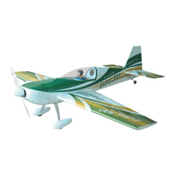
Instruction Manual
Requires : 4-channel radio w/ 4 micro servos,
Outrunner Motor w/ Propeller Adaptor
20A Brushless ESC, 3 cells 11.1V
2100mAh Li - Po battery & charger.
Wing Span
Wing Area
Flying Weight
Fuselage Length
Warning! This model is not a toy.
It is designed for maximum performance. Please seek advice if one is not familiar with this kind
of electric powered precision model. Operating this model without prior preparation may cause
injuries. Remember, safety is the most important thing. Always keep this instruction manual at
hand for quick reference.
THE WORLD MODELS
MANUFACTURING CO., LTD.
FACTORY PRE-FABRICATED
ALMOST-READY-TO-FLY (ARF) SERIES
MADE IN CHINA
www.theworldmodels.com
Specifications
*Specifications are subject to change without notice.*
INSTRUCTION MANUAL
40.5 in / 1030 mm
288 sq in / 18.6 sq dm
26.5 oz / 750 g
34.5 in / 880 mm
Advertisement
Table of Contents

Subscribe to Our Youtube Channel
Related Manuals for THE WORLD MODELS Extra 300 EP


Summary of Contents for THE WORLD MODELS Extra 300 EP
- Page 1 Operating this model without prior preparation may cause injuries. Remember, safety is the most important thing. Always keep this instruction manual at hand for quick reference. THE WORLD MODELS MANUFACTURING CO., LTD. FACTORY PRE-FABRICATED ALMOST-READY-TO-FLY (ARF) SERIES MADE IN CHINA www.theworldmodels.com...
-
Page 2: Before You Begin
INDEX BEFORE YOU BEGIN PARTS LIST ASSEMBLY P.3-P.10 SAFETY PRECAUTIONS P.10 BEFORE YOU BEGIN Read through the manual before you begin, so you will have an overall idea of what to do. Check all parts. If you find any defective or missing parts contact your local dealer. Please DRY FIT and check for defects for all parts that will require CA or Epoxy for final assembly. -
Page 3: Parts List
Parts List 1. MAIN WING -- 1 pair 9. MAIN LANDING GEAR -- 1 set MAIN WHEEL Ø40mm -- 2 pcs 2. SCREW PM2x14mm -- 4 pcs WHEEL PANTS -- 1 pair SCREW PA1.7x8mm -- 8 pcs SCREW PA2.6x10mm -- 3 pcs STRAPER -- 2 pcs SCREW PM3x25mm -- 2 pcs FUEL TUBE d2xD4x4mm -- 4 pcs... -
Page 4: Aileron Servo
Main Wing Aileron Servo Lead Apply instant type CA glue to both sides of each hinge. Bottom View Aileron Servo PA1.7x8mm Fuel Tube Straper d2xD4x4mm PM2x14mm Screw PA1.7x8mm Screw Ø1mm pilot holes for World Models tri-horn are pre-drilled. Please look for pin-hole marks at under side of control surfaces. -
Page 5: Stabilizer & Elevator
Stabilizer & Elevator Temporary install the main wing, adjust (Stabilizer) Apply instant type CA glue leveling of the stabilizer to make it as to both sides of each hinge. (Main Wing) parallel to the main wing as possible. *Also refer to step 13 Wing Setting Vertical Fin &... -
Page 6: Tail Landing Gear
Tail Landing Gear PA2x8mm Screw PA2x8mm PM2x8mm Screw 1.5mm M2 Nut 1.5mm Plastic Collar M2 Nut PM2x8mm Bottom View Ø1mm pilot holes for World Models horn are pre-drilled. Elevator Pushrod Please look for pin-hole marks at under side of control surfaces. PM2x10mm Screw 40mm PM2x10mm... -
Page 7: Main Landing Gear
Outrunner Motor / Cowling Optional Parts PM3x6mm Screw PWA2x8mm Screw Outrunner Motor 28/ 30 KM0283010 PM2x12mm Screw PA2.6x8mm Screw Make sure rotating Propeller Adaptor d3xD7mm Washer motor casing is not in (d3xD5) HW2340100 contact with wirings or anything. Don't over-tighten the PM3 screws, too much PM2x12mm stress on the screws... - Page 8 Main Wing Bottom 1.5mm Eye Screw PA2.5x10x23mm Bottom View Wing Tube D9.6x240mm Aileron Servo Lead Rubber Band...
-
Page 9: Radio Equipment
Radio Equipment Install and arrange the servo as shown in the diagram. Fuel Tube 20A Brushless ESC Front d2xD4x4mm Elevator Servo Double-Sided tape Elevator Servo Pushrod Connector Elevator Pushrod Ø1.4x70mm KA1.7x6mm J1(Pushrod Ø1.4x70mm) Battery Tie Straper Battery Receiver Rudder Servo Sponge J2(Pushrod Ø1.4x375mm) Canopy... - Page 10 Wing Setting Adjust the wing and fuselage configuration as shown in the diagrams. A=A' B=B' C=C'...
-
Page 11: Control Throws
Control Throws Adjust the control throws as shown in the diagram. These throws are good for general flying. You can adjust according to your personal preference. Rudder 30mm 30mm Elevator 20mm 20mm Aileron 10mm 10mm C.G. The ideal C.G. position is 63.5mm (2.5 in.) behind the leading edge measured at where the wing meets the fuselage. - Page 12 LINKAGE CONNECTOR HW7111050 & HW7111060 Drill 2mm hole at servo horn. Insert linkage connector into servo horn. Make sure shoulder of screw is cleared from servo horn. Add washer to reduce play if necessary. Shoulder Tighten up the round nut against the shoulder.
- Page 13 http://www.theworldmodels.com E252XM0803...
Need help?
Do you have a question about the Extra 300 EP and is the answer not in the manual?
Questions and answers