Table of Contents
Advertisement
Quick Links
Advertisement
Table of Contents

Related Manuals for Altusen KN9000


Summary of Contents for Altusen KN9000
-
Page 1: User Manual
User Manual KN9000 2004-05-04... -
Page 2: Fcc Information
Operation of this equipment in a residential area is likely to cause harmful interference in which case the user will be required to correct the interference at his own expense. ® © Copyright 2002-2004 ALTUSEN All brand names and trademarks are the registered property of their respective owners. 2004-05-04... -
Page 3: Package Contents
Package Contents The complete KN9000 package contains the following components: M 1 KN9000 KVM On the Net Control Unit M 1 CS Custom KVM Cable Set M 1 Rack Mounting Kit M 1 Software Disk M 1 Power Cord M 1 User Manual... - Page 4 2004-05-04...
-
Page 5: Table Of Contents
Contents 1. Introduction Overview ....... . . 1 Features ........3 System Requirements . - Page 6 Options ....... 52 The KN9000 List Panel ......53 Overview .
- Page 7 ALTUSEN Technical Support ..... 63 ALTUSEN Website ......64 Limited Warranty .
-
Page 8: About This Manual
Chapter 2, Hardware Setup, presents the front and back panel components, and explains how to connect the KN9000 to your server or KVM switch and the Internet. Chapter 3, The Administrator Utility, explains the Adminstrator Utility;... -
Page 9: Getting Help
Getting Help For additional help, advice, and information, ALTUSEN provides several support options. If you need to contact ALTUSEN technical support with a problem, please have the following information ready beforehand: M Product model number, serial number, and date of purchase. -
Page 10: Altusen Technical Support
ALTUSEN support website: http://www.altusen.com/support Product Information For information about all of ALTUSEN’s products and how they can help you connect without limits, visit ALTUSEN on the webat http://www.altusen.com ALTUSEN Authorized Resellers ALTUSEN provides the following ways to find an authorized reseller in your area:... -
Page 11: Introduction
Chapter 1. Introduction Overview The KN9000 is a control unit that uses the IP protocol to allow administrators to monitor and access their computers from remote locations. The KN9000 connects to the Internet, an Intranet, LAN, or WAN using industry standard Category 5 cable;... - Page 12 On the client side, both a Windows GUI Client and a Java Client are provided for IP connection and login to the KN9000 unit from anywhere on the net. The client software allows the user to view and control the servers connected to the KN9000.
-
Page 13: Features
System Requirements M For best results we recommend that the computers used to access the the KN9000 control unit have at least a P III 1 GHz processor, and that the screen resolution is set to 1024 x 768. M For the Windows Client, you must have DirectX 7.0 or higher installed. - Page 14 Notes: 2004-05-04...
-
Page 15: Hardware Setup
M The LED is OFF when data speed is 10 Mbps. 3. Link LED Flashes GREEN to indicate that a Client program has accessed the device. 4. Power LED Lights when the KN9000 is powered up and ready to operate. 2004-05-04... -
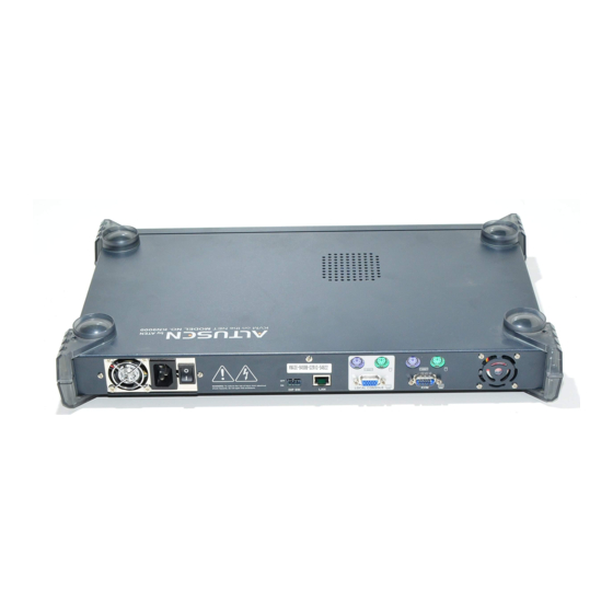
Page 16: Rear Panel
(or KVM switch) connected to the KN9000. 6. KVM Port Section The KVM cable that links the KN9000 to the server or KVM switch tplugs in here. Each port is indicated by an appropriate icon. -
Page 17: Installation
2. To prevent damage to your installation, make sure that all devices on the installation are properly grounded. To install the KN9000, refer to the diagram below (the numbers correspond to the numbered steps), and do the following: 1. Plug the local administrator’s keyboard, mouse, and monitor into the unit’s Console Ports. - Page 18 Notes: 2004-05-04...
-
Page 19: The Administrator Utility
Note: As a security feature, in order to save any changes that are made to the Administrator Utility, Segment 2 of the KN9000’s DIP Switch must be set to ON. Otherwise, the changes are discarded when you exit the program. - Page 20 If this is the first time that you are running the utility a dialog box appears requesting you to input your serial number. The serial number can be found on the bottom panel of the KN9000. Key in the serial number - 5 characters per box - then Click OK.
-
Page 21: Logging In
IP address (if one exists), to that device and attempts to connect again. 4. When the Administrator Utility searches for KN9000 devices, if it finds them in different network segments (one at 10.0.0.xxx, and another at 216.0.0.xxx, for example), it will attempt to substitute a dynamic IP address (10.0.0.111, for example). - Page 22 Username and Password. If you see this message, try logging in again being careful with the Username and Password If you successfully log in to the KN9000 with the default username and password, the following message appears: For security purposes, be sure to change the default Username and Password to something unique (see User Management, p.
-
Page 23: The Settings Notebook
The Settings Notebook Overview After successfully logging in, the Settings notebook appears: There are five tabs, each representing a different administrative activity. A description of each of the five activities and how to configure their settings is provided in the sections that follow. 2004-05-04... -
Page 24: Uploading Changes
Uploading Changes When settings have been configured to your satisfaction and you are ready to upload the changes to the KN9000: 1. Click OK to start the updating procedure. When updating has finished, the following message displays: 2. Click OK and you return to the Administration Utility device selection window (see p. -
Page 25: General
Device Name To make it easier to manage installations with more than one KN9000, each one can be given a name. To assign a name for this KN9000, erase the current name and key in one of your choosing (15 characters max.). -
Page 26: Network
As a security measure, the Administrator can set the Port numbers that the user must specify when he attempts to connect to a KN9000’s IP address. Unless the correct Port number is given, the KN9000 device will not be found. An... - Page 27 Log Server: Important transactions that occur on the KN9000, such as logins, internal status messages, etc., are kept in an automatically generated log file. Specify the MAC address and a Port number for the server you want the log file to reside on in the Log Server section.
-
Page 28: Security
Security The Security page is used to control access to the KN9000. M User station filters permit or deny access to the KN9000 for specific IP and MAC addresses attempting to access the system with KN9000 Client software. M The Java Access Page lets the Administrator specify the page that the user connects to when he uses the Java Client to access the KN9000. - Page 29 Filtering: M There are a maximum of 100 filters allowed for each category (User IPs, User MACs, and Administrator MACs). M To enable filtering for User Stations, Click to put a check mark in the IP and/or MAC Filter enable checkbox. M To add a filter, Click Add.
- Page 30 M If the include button is checked, all the addresses within the filter range are allowed access to the KN9000; all other addresses are denied access. M If the exclude button is checked, all the addresses within the filter range are denied access to the KN9000;...
-
Page 31: User Management
User Management This page is used to manage user profiles. It establishes the access rights of the users that connect to the KN9000. A maximum of 64 user profiles can be established. M To add a user profile, Click Add and fill in the information asked for in the User Management dialog box that appears. - Page 32 1. Checking Configure defines an Administrator who is allowed to configure the system, but does not have permission to access the KN9000 via the Java Client software. 2. Checking Java access defines a User who is allowed to access the KN9000 via the Java Client software, but does not have permission to configure the system.
-
Page 33: Customization
Working Modes If Stealth Mode is enabled, the KN9000 cannot be pinged. If Echo Mode is disabled, the KN9000 will not show up in the list of local KN9000 units (see p. 10 and p. 28) Reset on exit... -
Page 34: Upgrading The Firmware
New versions of the Mainboard, I/O Module, and Java Access Page firmware files can be downloaded from our website at http://altusen.com/downloads as they become available. To upgrade the firmware, do the following: 1. Go to the Customization page of the Administration configuration notebook (see p. - Page 35 3. Click Open. You return to the Customization page with the path to file, and the Upload version number displayed. Note: If you select the wrong file type for the component you are upgrading an Invalid file type message appears when you click Open.
-
Page 36: Java Authentication Page
Java Authentication Page As an important security feature, users who connect to the KN9000 via the Java Client must first log in before being allowed access. A Java Authentication Page that implements a Login (Username and Password) feature is provided on the distribution disk for this purpose. -
Page 37: The Windows Client
Starting Up To bring up the Windows Client Main Screen, run KN9000 Client either by double clicking (DClick) its icon, or by keying in the full path to KN9KClient.exe on the command line. -
Page 38: The Connection Screen
If this is the first time that you are running the program, a dialog box appears requesting you to input your serial number. If you don’t know what it is, contact the KN9000 administrator. Key in the serial number - 5 characters per box - then Click OK. - Page 39 DClick it. KN9000 IP: This area is used when you want to connect to a KN9000 at a remote location. You can drop down the list box and select an IP address or key in an IP address if the one you want isn’t listed, then key in the Port number in the Port field.
-
Page 40: The Tools Menu
The Tools Menu Tools menu operations are performed after you connect, but before you switch to remote view. There are two entries on the Tools Menu: Keyboard and Config. They are explained in the sections that follow. Keyboard Various configuration actions related to the keyboard, video, and mouse can be performed via hotkey combinations. - Page 41 Configuring the Hotkeys: If you find the default Hotkey combinations inconvenient, you can configure them to whatever suits your taste, as follows: 1. With the Hotkey Setup screen open, highlight the Action, then Click Start 2. Key in the Function keys (one at a time). The key names appear in the Key field as you press them.
-
Page 42: Config
Config When you select Config, a screen similar to the one below appears: If Keep screen size is not enabled (there is no checkmark in the box), the remote screen is resized to fit the resolution of your local monitor. If Keep screen size is enabled (there is a checkmark in the box), the remote screen is not resized. -
Page 43: Connecting
Connecting To connect to a KN9000 unit: 1. If it is in the KN9000 List, DClick it; if you are using the KN9000 IP input box, specify the IP address and Port number, then Click Open. A Login dialog box appears: 2. - Page 44 An explanation of the actions is given in the table, below: Action Explanation Exit remote location Break the connection to the KN9000 and return to local operation. Adjust video Brings up the video adjustment utility. Toggle OSD Toggles the OSD display Off and On (see Screen (OSD On/Off) Information, p.
-
Page 45: Operation
Operation Screen Information Once the connection to the KN9000 has been accomplished, a window opens on the Client’s monitor that exactly replicates the remote system’s video output display captured by the KN9000. Local keystroke and mouse input is captured and sent to the remote system. -
Page 46: Keystrokes
Mouse Synchronization Until you close the KN9000 connection, mouse movements have no effect on your local system, but are captured and sent to the remote system, instead. From time to time, especially if you change video resolution, the local mouse movement may no longer be synchronized with the remote system’s mouse... - Page 47 Windows 2000: Set the mouse speed to the middle position; set the mouse acceleration to None (Control Panel → Mouse → Mouse Properties → Motion): Windows XP/Server 2003: Set the mouse speed to the middle position; disable Enhance Pointer Precision (Control Panel →...
-
Page 48: Video Adjustment
WinMe: Set the mouse speed to the middle position; disable mouse acceleration (click Advanced to get the dialog box for this). WinNT / Win98 / Win95: Set the mouse speed to the slowest position. Video Adjustment You can adjust the placement and the picture quality of the remote screen (as displayed on your local monitor) with the Video Options function. - Page 49 The meanings of the adjustment options are given in the table below: Option Usage Screen Position Adjust the horizontal and vertical position of the remote computer window by Clicking the Arrow buttons. Auto-Sync Click Auto-Sync to have the function detect the vertical and horizontal offset values of the remote screen and automatically synchronize it with the local screen.
-
Page 50: Work Files
Work Files A Work File consists of all the information specified in a Client session. This includes the KN9000 and KN9000 IP list items, the Mouse Calibration settings, and the Hotkey and Video settings. Whenever a user runs the Client program, it opens with the values contained in the current work file. -
Page 51: The Java Client
The Java Client Introduction The Java Client is provided to make the KN9000 accessible to all platforms. Systems that have Java installed can connect. If you don’t already have Java, it is available for free download from Sun’s Java web site (http://java.sun.com). - Page 52 KN9000 administrator.) An Address Input dialog box appears: 5. Key in the IP address for the unit you want to connect to - including a forward slash followed by the name of the KN9000’s Java Client web page. For example: 168.10.95.001/kn9k.html Note: For security purposes, the name of the page that you connect to must be specified correctly as part of the IP address.
- Page 53 After you establish a connection, a Login dialog box appears: 6. Provide a valid Username and Password and Click OK. After a second or two, an Authentication progress window appears: Once the authentication procedure completes successfully, the remote system displays in a window on your monitor: 2004-05-04...
-
Page 54: Operation
Operation The remote system displays in a window on the upper portion of your monitor. You can work on the remote system via this screen just as if it were your local system. The Java Client’s toolbar is hidden in the blank area at the bottom center of the screen.When you move the mouse pointer over this area, the toolbar appears: Note: 1. -
Page 55: The Toolbar
Keypad: Clicking the second button, brings up the Keypad. Since some locally input keyboard combinations can not be captured and sent to the KN9000, the Keypad provides a one-click implementation of their actions on the remote system. 2004-05-04... - Page 56 Mouse: At times the local mouse movement may lose sync with the remote mouse movement. If performing an Autosync doesn’t resolve the problem The Mouse Synchronization function gets them back into sync. This is similar to the Mouse Synchronization feature of the Windows Client (see p. 36 for details). 1.
-
Page 57: The Log Server
Chapter 6. The Log Server The Windows-based KN9000 Log Server is an administrative utility that records all the events that take place on selected KN9000 units. Installation 1. Insert the Altusen software CD into your CD-ROM drive 2. Open the drive and folder where the Log Server Setup icon (KN9KlogServer.exe) is located and double click the icon. -
Page 58: Starting Up
The screen is divided into three components: M A Menu Bar at the top M A panel containing a list of KN9000 units in the middle (see p. 53 for details). M A panel containing an Events List at the bottom... -
Page 59: The Menu Bar
KN9000 units to the KN9000 List; edit the information for units already on the list; or delete KN9000s from the list. To edit or delete a listed KN9000, first select the one you want in the KN9000 List window, then open this menu and click Edit or Delete. -
Page 60: Events
A description of the fields is given in the table, below: Field Expalanation Address This can either be the IP address of the KN9000 or its DNS name (if the network administrator has assigned it a DNS name). Port The Port number assigned to the KN9000 (see p. 16). - Page 61 KN9000 List: KN9000 units are listed according to their IP address. Select the unit that you want to perform the search on from this list. You can select more than one unit for the search. If no units are selected, the search is performed on all of them.
-
Page 62: Options
Maintenance: This function allows the administrator to perform manual maintenance of the database. He can use it to erase specified records before the expiration time that was set with the Limit setting of the Edit function (see p. 50). Options Network Retry allows you to set the number of seconds that the Log Server should wait before attempting to connect if its previous attempt to connect failed. -
Page 63: The Kn9000 List Panel
The KN9000 List Panel Overview The KN9000 List panel (refer back to the figure on p. 48), displays a list of all the KN9000 units that have been selected for the Log Server to track (see Configure, p. 49). Tick information for the currently selected KN9000 displays in the Events List panel below. -
Page 64: The Event List Window
The Event List Window This window displays tick information for the currently selected KN9000. Note that even though any other KN9000s aren’t currently selected, if their Recording checkbox is checked, the Log Server records their tick information and keeps it in its database. -
Page 65: Appendix A. Troubleshooting
Appendix A. Troubleshooting General Operation Problem Resolution Erratic Operation If the KN9000 is connected to a KVM switch, make sure to power on the switch before powering on the KN9000. The Administrator Utility Problem Resolution Unable to enter the Make sure that the KN9000’s DIP Switch segment 2... -
Page 66: The Java Client
Action Java Client won’t 1. Make sure to include the correct name of the web page connect to the when you specify the KN9000’s IP address. KN9000 2. Close the Java Client, reopen it, and try again. Pressing the Java doesn’t support the Windows Menu key. -
Page 67: Sun Systems
Sun Systems Problem Resolution Video display problems with The display resolution should be set to 1024 x 768: HDB15 interface systems (e.g., Sun Blade 1000 servers). Under Text Mode: 1. Go to OK mode and issue the following commands: setenv output-device screen:r1024x768x60 reset-all Under XWindow: 1. - Page 68 Notes: 2004-05-04...
-
Page 69: Specifications
Appendix B. Specifications Function Specification Connectors Console 1 x 6 pin mini-DIN F - Keyboard Ports 1 x 6 pin mini-DIN F - Mouse 1 x HDB-15 F - Video 1 x 6 pin mini-DIN F - Keyboard Ports 1 x 6 pin mini-DIN F - Mouse 1 x HDB-15 M - Video 1 x RJ-45 Receptacle Power... - Page 70 Notes: 2004-05-04...
-
Page 71: Appendix C. Stacking And Mounting
Stacking and Mounting Stacking KN9000 devices can be stacked one on top of the other using the stacking brackets that come already attached to the unit. Note that there is a top and bottom half to each bracket. The top half has a convex surface;... -
Page 72: Rack Mounting
Rack Mounting To rack mount the unit do the following: 1. First remove the stacking brackets by unscrewing them from the unit, as shown in the diagram below: 2. Next screw the mounting brackets into the sides of the unit, as shown in the diagram below: 3. -
Page 73: Appendix D. Technical Support
This service is available 24 hours a day, 7 days a week. If you are experiencing difficulty getting this product to work correctly, please do not hesitate to call. In North America, the ALTUSEN Technical Phone Support Center can be reached at 888-999-ALTUSEN (888-999-2836). Outside of North America, call the nearest ALTUSEN Technical Support Phone Center. -
Page 74: Altusen Website
ALTUSEN Website The ALTUSEN website has the latest information about this product. Firmware upgrades can be found at the site, as well. You can access the ALTUSEN website at http://www.Altusen.com. Limited Warranty IN NO EVENT SHALL THE DIRECT VENDOR’S LIABILITY EXCEED THE PRICE PAID FOR... - Page 75 Installation ....47 KN9000 List Window ..53 Main Screen ....48 Fast auto-sync .
- Page 76 Login Invalid login....12 Technical Support ... . . 63 Login failure ....23 Time out control.
Need help?
Do you have a question about the KN9000 and is the answer not in the manual?
Questions and answers