Table of Contents
Advertisement
Quick Links
Advertisement
Table of Contents

Subscribe to Our Youtube Channel
Related Manuals for Altusen ALTUSEN KN2108


Summary of Contents for Altusen ALTUSEN KN2108
- Page 1 8/16 Port KVM Over the NET™ KN2108 / KN2116 User Manual www.altusen.com.tw...
-
Page 2: Regulatory Information
KN2108 / KN2116 User Manual Regulatory Information This is an FCC Class A product. In a domestic environment this product may cause radio interference in which case the user may be required to take adequate measures. This equipment has been tested and found to comply with the limits for a Class A digital device, pursuant to Part 15 of the FCC Rules. -
Page 3: User Information
886-2-8692-6959 China 86-10-5160-1602 Japan 81-3-5323-7178 Korea 82-2-467-6789 North America ATEN TECH 1-888-999-ATEN ATEN NJ 1-732-356-1703 United Kingdom 44-8-4481-58923 User Notice All information, documentation, and specifications contained in this manual are subject to change without prior notification by the manufacturer. The... -
Page 4: Package Contents
Manual Part No. PAPE-0206-1AXG F/W Version: v1.1.101 Manual Date: 2010-01-12 ATEN and the ATEN logo are registered trademarks of ATEN International Co., Ltd. All rights reserved. All other brand names and trademarks are the registered property of their respective owners. -
Page 5: Table Of Contents
KN2108 / KN2116 User Manual Contents Regulatory Information ........ii RoHS. - Page 6 KN2108 / KN2116 User Manual Rack Mounting – Front ........15 Rack Mounting –...
- Page 7 KN2108 / KN2116 User Manual Access Port ..........51 Log Server .
- Page 8 KN2108 / KN2116 User Manual Chapter 6. The User Interface The Main Page ..........77 Port Operation .
- Page 9 KN2108 / KN2116 User Manual Options ..........118 The Log Server Main Screen .
- Page 10 KN2108 / KN2116 User Manual Certificate Trusted........147 Self-Signed Private Certificates .
-
Page 11: About This Manual
KN2108 / KN2116 User Manual About This Manual This User Manual is provided to help you get the most from your KN2108 / KN2116 system. It covers all aspects of installation, configuration and operation. An overview of the information in the manual is provided below. Chapter 1, Introduction, introduces you to the KN2108 / KN2116 System. -
Page 12: Conventions
KN2108 / KN2116 User Manual Conventions This manual uses the following conventions: Monospaced Indicates text that you should key in. Indicates keys you should press. For example, [Enter] means to press the Enter key. If keys need to be chorded, they appear together in the same bracket with a plus sign between them: [Ctrl+Alt]. -
Page 13: Terminology
For information about all ALTUSEN products and how they can help you connect without limits, visit ALTUSEN on the Web or contact an ALTUSEN Authorized Reseller. Visit ALTUSEN on the Web for a list of locations and telephone numbers: International http://www.aten.com North America ATEN TECH http://www.aten-usa.com ATEN NJ http://www.aten.com xiii... - Page 14 KN2108 / KN2116 User Manual This Page Intentionally Left Blank...
-
Page 15: Chapter 1 Introduction
Chapter 1 Introduction Overview The KN2108 and KN2116 are IP-based KVM control units that allow both local and remote operators to monitor and access multiple computers from a single console. For example, a single KN2116 can control up to 16 computers. By cascading up to 16 compatible KVM switches, up to 256 computers can be controlled on a complete two stage installation. - Page 16 KN2108 / KN2116 User Manual Remote operators can log in from anywhere on the net via their browser. Once they successfully log in, operators can take control using either the Windows Client or Java Client utility. Inclusion of a Java-based client allows the switches work with Java 2 enabled operating systems.
-
Page 17: Features
Chapter 1. Introduction Features 8 (KN2108) or 16 (KN2116) port remote access KVM switch – monitor and control up to 8 or 16 computers from a single KVM console Remotely access computers via LAN, WAN, or the Internet; control your installation when and where you want Supports 3 bus sessions –... -
Page 18: System Requirements
KN2108 / KN2116 User Manual System Requirements Remote User Computers Remote user computers (also referred to as client computers) are the ones the users log into the switch with from remote locations over the internet (see Terminology, page xiii). The following equipment must be installed on these computers: For best results we recommend that the computers used to access the switch have at least a P III 1 GHz processor, with their screen resolution... -
Page 19: Video
Chapter 1. Introduction Video Only the following non-interlaced video signals are supported: Resolution Refresh Rates 640 x 480 60, 70, 75, 85 720 x 400 70, 75 800 x 600 56, 60, 70, 75, 85 1024 x 768 60, 70, 75, 85 1152 x 864 60, 70, 75 1280 x 1024... -
Page 20: Operating Systems
KN2108 / KN2116 User Manual Operating Systems Supported operating systems for remote user computers that log into the KVM Over the NET switch include Windows 2000 and higher, and those capable of running Sun's Java Runtime Environment (JRE) 6, Update 3, or higher (Linux, Mac, Sun, etc.). Supported operating systems for the servers that are connected to the switch’s ports are shown in the table, below: Version... -
Page 21: Components
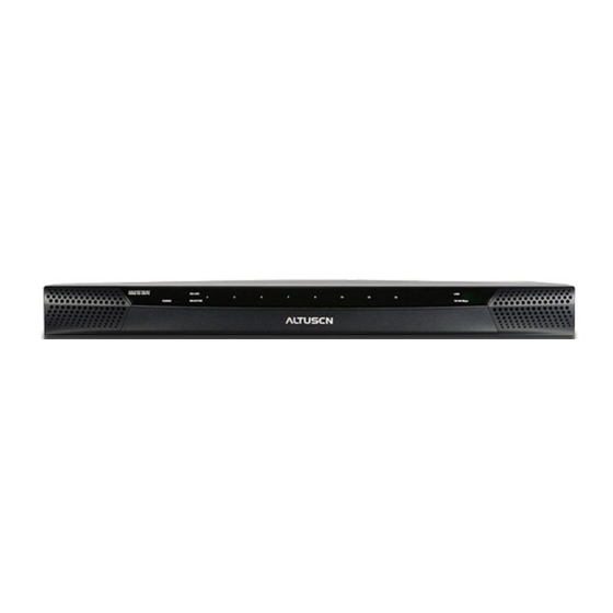
Chapter 1. Introduction Components Front View KN2108: KN2116:... - Page 22 KN2108 / KN2116 User Manual Component Description Power LED Lights when the KN2116 is powered up and ready to operate. Port LEDs The Port LEDs provide status information about their corresponding CPU Ports. There is one pair of LEDs for each Port.
-
Page 23: Rear View
Chapter 1. Introduction Rear View KN2108: KN2116:... - Page 24 KN2108 / KN2116 User Manual Component Description Power Socket The power cable plugs in here. Power Switch This standard rocker switch powers the unit on and off. PON Port This connector is provided for a Power over the Net™ (PON) unit to plug into. A PON device allows computers attached to the KN2116 to be booted remotely over the net.
-
Page 25: Chapter 2. Hardware Setup
Chapter 2 Hardware Setup Overview For convenience and flexibility that allows mixing the PS/2 and USB interfaces, as well as multiple platforms, the KN2108 / KN2116's design utilizes KVM Adapter Cables, that serve as intermediaries between the switch and the connected devices (refer to the KVM Adapter Installation Diagrams, page 21). -
Page 26: Stacking And Rack Mounting
KN2108 / KN2116 User Manual Stacking and Rack Mounting The KN2108 / KN2116 can be stacked on the desktop or rack mounted in a variety of ways. The following sections take you through the procedures for each method. Stacking The KN2108 / KN2116 can be placed on any appropriate level surface that can safely support its weight plus the weight of its attached cables. -
Page 27: Rack Mounting - Split
Chapter 2. Hardware Setup Rack Mounting - Split The KN2108 / KN2116 can be installed in most standard 19" (1U) racks. There are three configurations: split; front; and rear. Of the three, we recommend the split method. 1. Remove the four screws at the front and rear of the unit: Phillips head hex M3 x 6 2. - Page 28 KN2108 / KN2116 User Manual 3. Position the device in the rack and align the holes in the mounting brackets with the holes in the rack. 4. Screw the mounting brackets to the rack. Note: Cage nuts are provided for racks that are not pre threaded.
-
Page 29: Rack Mounting - Front
Chapter 2. Hardware Setup Rack Mounting - Front 1. Remove the two screws at the front of the unit: Phillips head hex M3 x 6 2. Use the M3 x 8 Phillips head hex screws supplied with the rack mount kit to screw the rack mounting brackets into the front of the unit: Phillips head hex M3 x 8... - Page 30 KN2108 / KN2116 User Manual 3. Position the device in the rack and align the holes in the mounting brackets with the holes in the rack. 4. Screw the mounting brackets to the front of the rack. Note: Cage nuts are provided for racks that are not pre threaded.
-
Page 31: Rack Mounting - Rear
Chapter 2. Hardware Setup Rack Mounting - Rear 1. Remove the two screws at the rear of the unit: Phillips head hex M3 x 6 2. Use the M3 x 8 Phillips head hex screws supplied with the rack mount kit to screw the rack mounting brackets into the rear of the unit: Phillips head hex M3 x 8... - Page 32 KN2108 / KN2116 User Manual 3. Position the device in the rack and align the holes in the mounting brackets with the holes in the rack. 4. Screw the mounting brackets to the rear of the rack. Note: Cage nuts are provided for racks that are not pre threaded.
-
Page 33: Single Station Installation
Chapter 2. Hardware Setup Single Station Installation In a Single Stage installation, there are no additional KVM switches cascaded down from the KN2108 / KN2116. To set up a single stage installation, refer to the installation diagrams starting on page 20 (the numbers in the diagram correspond with the numbers of the instruction steps), and do the following: 1. -
Page 34: Single Stage Installation Diagram
KN2108 / KN2116 User Manual Single Stage Installation Diagram... -
Page 35: Kvm Adapter Installation Diagrams
Chapter 2. Hardware Setup KVM Adapter Installation Diagrams KA9120 KA9131 KA9170 KA9140 SERIAL TERMINAL KA9130... -
Page 36: Two Stage Installation
KN2108 / KN2116 User Manual Two Stage Installation To control even more computers, up to 8 (KN2108) or 16 (KN2116) additional KVM switches can be cascaded from the KVM ports of the KN2108 or KN2116. As many as 64 (KN2108) or 128 (KN2116) computers can be controlled in a complete two stage installation. -
Page 37: Two Stage Installation Diagram
Chapter 2. Hardware Setup 8. Turn on the power to all the computers. Note: The Power On sequence requires that all Second Stage units be powered on first. After all the Second Stage units have been powered on, the First Stage unit must be powered on next. After the Second and First stage units have been powered on, the computers can be powered on. -
Page 38: Hot Plugging
KN2108 / KN2116 User Manual Hot Plugging The KN2108 / KN2116 supports hot plugging - components can be removed and added back into the installation by unplugging and replugging their cables from the ports without the need to shut the unit down. If you change computer positions, however, in order for the OSD menus to correspond to the KVM port changes, you must manually reedit the Port Names to have the OSD reflect the new Port information. -
Page 39: Port Id Numbering
Chapter 2. Hardware Setup Port ID Numbering Each computer on the installation is assigned a unique Port ID. The Port ID is a one or two segment number that is determined by the Stage Level and KVM Port number of the KVM switch that the computer is connected to. The first segment represents the KVM Port number of the First Stage unit;... - Page 40 KN2108 / KN2116 User Manual This Page Intentionally Left Blank...
-
Page 41: Chapter 3 Logging In
Chapter 3 Logging In Overview KN2108 / KN2116 switches can be accessed from a local console; an internet browser; a Windows application (AP) program; and a Java application (AP) program. No matter which access method you choose, the switch’s authentication procedure requires you to submit a valid username and password. -
Page 42: Browser Login
KN2108 / KN2116 User Manual Browser Login To log into the KN2108 / KN2116 from an Internet browser: 1. Open the browser and specify the IP address in the URL bar. Note: For security purposes, a login string may have been set by the Administrator (See Security, page 59, for details). -
Page 43: Winclient Ap Login
Chapter 3. Logging In WinClient AP Login In some cases, the Administrator may not want the KN2108 / KN2116 to be available via browser access. AP versions of the WinClient and the Java Client are provided to enable direct access of the KN2108 / KN2116 without having to go through a browser. -
Page 44: Starting Up
KN2108 / KN2116 User Manual Starting Up To connect to the KN2108 / KN2116, go to the location on your hard disk that you saved the WinClient AP program to, and double-click its icon (WinClient.exe) to bring up the WinClient AP Screen: Note: You must have DirectX 8.0 or higher installed on your computer. -
Page 45: The Connection Screen
Chapter 3. Logging In The Connection Screen A description of the Connection Screen is given in the following table Item Description Menu Bar The Menu Bar contains two items: File and Help. The File Menu allows the operator to Create, Save, and Open user created Work files (see page 32 for details). -
Page 46: The File Menu
KN2108 / KN2116 User Manual The File Menu The File Menu allows the operator to Create, Save, and Open user created Work files. A Work File consists of all the information specified in a Client session. This includes the Server List and Server IP list items, as well as the Hotkey settings. -
Page 47: Connecting
Chapter 3. Logging In Connecting To connect to a KN2108 / KN2116 unit: 1. From the Server List box, double-click the device that you wish to connect to. Or, specify the IP address and port number in the Server IP and Port input boxes, and then Click Connect. -
Page 48: Operation
KN2108 / KN2116 User Manual Operation Once a connection to the KN2108 / KN2116 has been established, the remote system's video output is captured and displayed on your monitor. At the same time, your local keystroke and mouse input is captured and sent to the remote system. -
Page 49: Java Client Ap Login
Chapter 3. Logging In Java Client AP Login Installation To install the Java Client on your computer, do the following: 1. Log into the KN2108 / KN2116 with your browser, and click the second Java Client button (the one with the arrow). A screen similar to the one below appears: 2. -
Page 50: Operation
KN2108 / KN2116 User Manual 2. Key in the IP address for the unit you want to connect to – including a forward slash followed by the login string (set by the administrator). Note: 1. If the system administrator set the switch’s Program port to something other than the default you must specify the port number along with the IP address. -
Page 51: Chapter 4. Administration
Chapter 4 Administration Overview The OSD's Administration page lets the Administrator (and users with administration permission – see User Management, page 48) configure and control overall KN2108 / KN2116 operations. The tab that activates the page is disabled (grayed out) for users who do not have administration permission. The Local Console Once the KN2108 / KN2116 has been cabled up, the next step that the Administrator needs to perform is setting the unit up for user operation. - Page 52 KN2108 / KN2116 User Manual After you successfully log in, the Local Console OSD comes up: The OSD consists of four pages, each with a specific set of functions: Main; Configuration; Administration; and Log. Each of these pages is discussed in the sections that follow There are four buttons at the right of the title bar.
-
Page 53: The Main Page
Chapter 4. Administration The Main Page The Main page lists all of the KN2108 / KN2116’s ports and governs port access. Selecting a port and double clicking it switches you to the device on that port. A port icon in the shape of a monitor displays in front of the port number. Ports that have devices connected to them that are up and running have the port icon lit in green. -
Page 54: The List Function
KN2108 / KN2116 User Manual The List Function The List Function lets you broaden or narrow the scope of which ports the OSD displays (lists) in the Main Screen. To invoke the List Function, click the arrow at the upper right corner of the screen, or press [F3]: The screen changes to allow you to choose the ports that will be listed:... - Page 55 Chapter 4. Administration The drop down list on the left offers four fixed choices as shown in the table, below: Choice Meaning Lists all of the ports on the installation. Powered On Lists only the ports that have their attached devices powered on.
-
Page 56: Port Names
KN2108 / KN2116 User Manual Port Names To help remember which computer is attached to a particular port, every port can be given a name. This field allows the Administrator to create, modify, or delete port names. To configure a port name: 1. -
Page 57: Port Operation
Chapter 4. Administration 2. Key in the new Port Name, or modify/delete the old one. 3. When you have finished editing the port name, click anywhere outside of the input box to complete the operation. Port Operation Since port operation is the same as for the Windows and Java Clients, the procedures are discussed in Chapters 5 and 6. -
Page 58: The Configuration Page
KN2108 / KN2116 User Manual The Configuration Page The OSD Configuration page allows users to set up their own, individual, working environments. The KN2108 / KN2116 stores a separate configuration record for each user profile, and sets up the working configuration according to the Username that is used to log in. - Page 59 Chapter 4. Administration The Configuration page settings are explained in the following table: Setting Function OSD Hotkey Selects which Hotkey controls the OSD function: [Scroll Lock] [Scroll Lock] or [Ctrl] [Ctrl]. Since the Ctrl key combination may conflict with programs running on the computers, the default is the Scroll Lock combination (see Hotkey Operation, page 67).
-
Page 60: The Log Page
KN2108 / KN2116 User Manual The Log Page Note: Only the Local Console OSD has the Log tab. The Web browser and AP versions do not. However, the log can be access through the browser via the Log icon. See Web Page Icons, page 71. Clicking the Log tab brings up the contents of the log file. -
Page 61: The Administration Page
Chapter 4. Administration The Administration Page Each of the administrative functions is represented by an icon at the left of the page. Clicking the icon brings up its associated dialog box. When the Administration page first comes up the General dialog box appears: General The General Page presents four items of information. -
Page 62: User Management
KN2108 / KN2116 User Manual User Management The User Management dialogs are used to create and manage user profiles. Up to 64 user profiles can be established. To delete a user profile, select it in the list box, and Click Remove. To modify a user profile, select it and Click Edit. - Page 63 Chapter 4. Administration Fill in the required information for a new User profile, or modify the existing information to edit a previous profile. A description of the field headings is given in the table below: Heading Description Username A minimum of 6 and a maximum of 15 characters is allowed. Password A minimum of 8 and a maximum of 15 characters is allowed.
- Page 64 KN2108 / KN2116 User Manual (Continued from previous page.) Heading Description Port Access This function allows the Administrator or a User with Administration permission to define the selected User's access to the computers on a Port-by-Port basis. For each User profile, select a port and click it to cycle through the choices: Full: The user can view the remote screen and can perform operations on the remote system from his...
-
Page 65: Service Configuration
Chapter 4. Administration Service Configuration The Service Configuration dialog is composed of two main panels: Access Port and Log Server: Access Port As a security measure, if a firewall is being used, the Administrator can specify the port numbers that the firewall will allow, and set the firewall accordingly. Users must specify the port number when they log in to the KN2108 / KN2116. -
Page 66: Log Server
KN2108 / KN2116 User Manual Log Server Important transactions that occur on the KN2108 / KN2116, such as logins and internal status messages, are kept in an automatically generated log file. You specify the MAC address and a port number for the computer that the Log Server resides on in this panel. -
Page 67: Network
Chapter 4. Administration Network The Network dialog is used to specify the KN2108 / KN2116's network environment. The box is divided into two panels: IP Address; and DNS Server. Network Transfer Rate This setting allows you to tailor the size of the data transfer stream to match network traffic conditions by setting the rate at which the KN2108 / KN2116 transfers data between the switch and the client computers. -
Page 68: Anms
KN2108 / KN2116 User Manual ANMS The Advanced Network Management Settings page is used to set up login authentication and authorization management from external sources. Click on the ANMS icon to select RADIUS, LDAP, or CC Management. RADIUS If you are using a RADIUS server, set up its parameters as follows: 1. - Page 69 Chapter 4. Administration (Continued from previous page.) 3. Set the time in seconds that the KN2108 / KN2116 waits for a RADIUS server reply before it times out in the Timeout field. 4. Set the number of RADIUS retries allowed in the Retries field. 5.
-
Page 70: Radius Server Access Rights Table
KN2108 / KN2116 User Manual RADIUS Server Access Rights Table: Character Meaning Grants the user administrator privileges, allowing the user to configure the system. Allows the user to access the system via the WinClient ActiveX Viewer program. Allows the user to access the system via the Java Client program. Allows the user to access an attached Power Over the Net™... -
Page 71: Ldap / Ldaps
LDAPS server reply before it times out. 5. Consult the LDAP / LDAPS administrator to ascertain the appropriate entry for this field. For example, the entry might look like this: ou=kn4132,dc=aten,dc=com 6. Key in the LDAP administrator’s username. 7. Key in the LDAP administrator’s password. -
Page 72: Cc Management Settings
KN2108 / KN2116 User Manual CC Management Settings If you want to allow authorization for the KN2108 / KN2116 through a CC (Control Center) server, check Enable CC Management and fill in the CC Server’s IP address and the port that it listens on in the appropriate fields. Note:The current firmware (insert firmware version) supports CC1000 only. -
Page 73: Security
Chapter 4. Administration Security The Security page controls access to the KN2108 / KN2116. IP and MAC Filtering If any filters have been configured, they appear in the IP Filter and/or MAC Filter list boxes. IP and MAC Filters control access to the KN2108 / KN2116 based on the IP and/or MAC addresses of the computers attempting to connect. -
Page 74: Default Web Page Name
KN2108 / KN2116 User Manual Note: Each IP filter can consist of a single address, or a range of addresses. To filter a single IP address, key in the same address in both the From and To fields. To filter a continuous range of IP addresses, key in the start of the range in the From field;... -
Page 75: Customization
Chapter 4. Administration Customization The Customization dialog box is arranged in four major sections, as described below: Login Failures Allowed: sets the number of consecutive failed login attempts that are permitted from a remote computer. Timeout: sets the amount of time a remote computer must wait before attempting to login again after it has exceeded the number of allowed failures. -
Page 76: I/O Modules
KN2108 / KN2116 User Manual I/O Modules Upgrade: Upgrade allows you to upgrade the I/O firmware of selected ports. When you click Upgrade..., a dialog box similar to the one below appears: 1. Select the ports you want to upgrade. Note: The port’s status is displayed in the field to its right. -
Page 77: Attributes
Chapter 4. Administration Attributes: Attributes allows you to set attribute parameters for each of the ports. When you click Attributes..., a dialog box similar to the one below appears: The port numbers are listed in the column on the left. The port's attributes are shown to its right. -
Page 78: Share Mode Attribute Table
KN2108 / KN2116 User Manual The Timeout field sets a time threshold for users on ports whose Share Mode has been set to Occupy (see Occupy:, page 64). If there is no activity from the user occupying the port for the amount of time set here, the user is timed out and the port is released. -
Page 79: Miscellaneous
Chapter 4. Administration 1. Select the desired attributes for the port, then click OK. You return to the previous screen (Setting I/O Module Attributes). To exit without saving your changes, click Cancel. 2. When you return to the previous screen, click Apply to keep your changes. To exit without saving your changes, click Cancel. -
Page 80: Date/Time
KN2108 / KN2116 User Manual Date/Time Note: Only the Local Console OSD has the Date/Time function. The Web browser versions do not. The Date/Time dialog box lets the Administrator set up the KN2108 / KN2116's time parameters: To establish the time zone that the switch is located in, drop down the Time Zone list and choose the city that most closely corresponds to where it is at. -
Page 81: Upgrading The Firmware
Chapter 4. Administration Upgrading the Firmware As new versions of the KN2108 / KN2116 firmware become available, they can be downloaded from our website. Check the web site regularly to find the latest information and packages. Note: Although upgrading the firmware isn’t on the OSD Administration page, it is an administration function, so we will discuss it in this chapter. - Page 82 KN2108 / KN2116 User Manual This Page Intentionally Left Blank...
-
Page 83: Chapter 5. Browser Operation
Chapter 5 Browser Operation Overview After you have successfully logged in (see Logging In, page 27), the KN2108 / KN2116 Main Web page appears. All of the features are described in the sections that follow. Main Web Page The Main Web page appears with the General dialog box displayed: Note: 1. -
Page 84: Web Page Layout
KN2108 / KN2116 User Manual Web Page Layout There are four icons at the top of the web page: General; Sync; Maintenance; and Logout, as follows: The General Dialog Box An explanation of the General dialog box fields is given in the table below: Field Purpose Device Name... -
Page 85: Web Page Icons
Chapter 5. Browser Operation Web Page Icons The purpose of the other icons at the top of the web page are explained in the table below: Icon Function Click this icon to synchronize the KN2108 / KN2116's time with your computer's time. If both are in the same time zone, the device's time is changed to match the computer's time. -
Page 86: Maintenance
KN2108 / KN2116 User Manual Maintenance The Maintenance page allows the Administrator to upgrade the KN2108 / KN2116’s firmware, and to download a private encryption key and signed certificate. Upgrading the Firmware As new versions of the KN2108 / KN2116 firmware become available, they can be downloaded from our website. -
Page 87: Private Certificate
For enhanced security, the Private Certificate section allows you to use your own private encryption key and signed certificate, rather than the default ATEN certificate. To do this, click the Maintenance icon (see page 69) to open the Private... -
Page 88: Web Page Buttons
KN2108 / KN2116 User Manual Web Page Buttons The purpose of the buttons at the left of the web page are explained in the table below: Icon Purpose Click this button to open the WinClient ActiveX Viewer software to remotely control the KN2108 / KN2116 and the devices connected to it. -
Page 89: Activating The Winclient Activex Viewer
Chapter 5. Browser Operation Activating the WinClient ActiveX Viewer After you have successfully logged in (see Browser Login, page 28), to activate the browser-based WinClient ActiveX Viewer do the following: 1. Click the Windows Client button (the one without the arrow) at the left of the web page. -
Page 90: Activating The Java Applet Viewer
KN2108 / KN2116 User Manual Activating the Java Applet Viewer After you have successfully logged in (see page 27), to activate the Java Applet Viewer, do the following: 1. Click the Java Client button (the one without the arrow) at the left of the web page. -
Page 91: Chapter 6. The User Interface
Chapter 6 The User Interface Overview Once you have successfully logged in (see Logging In, page 27), activate the browser-based OSD. The look of the user interface main page varies slightly, depending on which method you used to log in (WinClient ActiveX Viewer, WinClient AP Control Panel, Java Applet Viewer, or Java Client AP Control Panel). - Page 92 KN2108 / KN2116 User Manual Log out: clicking this button (or pressing F8) closes the OSD display and logs you out of the KN2108 / KN2116 session. Close: clicking this button closes the OSD display but does not log you out of the session.
-
Page 93: Port Operation
Chapter 6. The User Interface Port Operation Select a port on the OSD Main Screen either by moving the highlight bar to it with the Up and Down Arrow keys and pressing Enter, or by double-clicking it. Once you select a port, its screen displays on you monitor, and your keyboard and mouse input affects the remote system. -
Page 94: Osd Hotkey Summary Table
KN2108 / KN2116 User Manual OSD Hotkey Summary Table The following table presents a summary of the OSD Hotkey actions. To set the OSD Hotkey, see OSD Hotkey, page 109. To... When... Do This... Open the OSD The OSD Toolbar is not open. Click the OSD Hotkey twice. -
Page 95: Hotkey Operation
Chapter 6. The User Interface Hotkey Operation Hotkeys allow you to provide KVM focus to a port directly from the keyboard. The KN2108 / KN2116 provides the following hotkey features: Auto Scanning Skip Mode Switching The hotkeys are: A and P for Auto Scanning; and the Arrow Keys for Skip Mode. -
Page 96: Pausing Auto Scan
KN2108 / KN2116 User Manual Pausing Auto Scan While you are in Auto Scan Mode, you can pause the scanning in order to keep the focus on a particular computer by pressing P. During the time that Auto Scanning is paused, the S in front of the Port ID blinks On and Off. Pausing when you want to keep the focus on a particular computer is more convenient than Exiting Auto Scan Mode because when you Resume scanning, you start from where you left off. -
Page 97: Panel Array Mode
Chapter 6. The User Interface Panel Array Mode Clicking on the OSD Toolbar's Panel icon invokes Panel Array Mode. Under this mode, the OSD divides your screen into a 4 x 4 grid of 16 panels: Each panel represents one of the KN2108 / KN2116's ports. Starting with Port 1 at the upper left;... - Page 98 KN2108 / KN2116 User Manual (Continued from previous page.) You can access a computer connected to a port by moving the mouse pointer over its panel and clicking. You switch to the computer exactly as if you had selected it from the OSD Main screen. The panel array toolbar, at the lower right of the screen, provides shortcut navigation and control of the panel array as described in the diagram below:...
-
Page 99: Multiuser Operation
Note: ATEN recommends that the user who starts Panel Array Mode set it to display at least four panels; otherwise, it is possible that other users may receive only part of the picture. -
Page 100: Control Panel
KN2108 / KN2116 User Manual Control Panel Since the WinClient ActiveX Viewer and WinClient AP Control Panel contains the most complete functionality of all the user interface control panels, this section describes the WinClient Control Panel. Although the other control panels may not have all of the features that this one does, you can refer to the information described here when using them. - Page 101 Chapter 6. The User Interface Right clicking in the text row area brings up a menu that allows you to select options for the Screen Mode, Zoom and Macro List. These functions are discussed in the sections that follow. To move the Control Panel to a different location on the screen, place the mouse pointer over the text bar area, then click and drag.
-
Page 102: Control Panel Functions
KN2108 / KN2116 User Manual Control Panel Functions Icon Function This is a toggle. Click to make the Control Panel persistent – i.e., it always displays on top of other screen elements. Click again to have it display normally. Click to bring up the Macros dialog box (see page 90 for details). - Page 103 Chapter 6. The User Interface These icons show the Num Lock, Caps Lock, and Scroll Lock status of the remote computer. When the lock state is On, the LED is bright green and the lock hasp is closed. When the lock state is Off, the LED is dull green and the lock hasp is open.
-
Page 104: Macros
KN2108 / KN2116 User Manual Macros The Macros icon provides access to two functions found in the Macros dialog box: Hotkeys and User Macros. Both are described in the following sections. Note: The T button at the top right of the dialog boxes that appear for the Macros function brings up a slider to adjust the transparency of the dialog box. - Page 105 Chapter 6. The User Interface An explanation of the Hotkey actions is given in the table below: Action Explanation Exit remote If you are using the Java AP, this exits the remote view and goes back to the web browser Main Page. If you are using the WinClient AP, this exits location remote view and goes back to the WinClient main page.
-
Page 106: User Macros
KN2108 / KN2116 User Manual User Macros User Macros are used to perform specific actions on the remote server. To create the macro, do the following: 1. Select User Macros radio button, then click Add. 2. In the dialog box that comes up, replace the “New Macro” text with a name of your choice for the macro:... - Page 107 Chapter 6. The User Interface 3. Click Record. The dialog box disappears, and a small panel appears at the top left of the screen: 4. Press the keys for the macro. To pause macro recording, click Pause. To resume, click Pause again. Clicking Show brings up a dialog box that lists each keystroke that you make, together with the amount of time each one takes: Clicking Cancel cancels all keystrokes.
- Page 108 KN2108 / KN2116 User Manual 5. If you haven’t brought up the Show dialog, click Done when you have finished recording your macro. You return to the Macros dialog box with your system macro key presses displayed in the Macro column: 6.
- Page 109 Chapter 6. The User Interface After creating your macros, you can run them either by opening this dialog box and clicking Play, or by opening the Macro List on the Control Panel and clicking the one you want. If you run the macro from this dialog box, you have the option of specifying how the macro runs, by clicking the arrow next to the Play button.
-
Page 110: Video Settings
KN2108 / KN2116 User Manual Video Settings Clicking the Hammer icon on the Control Panel brings up the Video Settings dialog box. The options in this dialog box allow you to adjust the placement and picture quality of the remote screen on your monitor The meanings of the video adjustment options are given in the table on the following two pages:... - Page 111 Chapter 6. The User Interface Video adjustment options: Options Usage Screen Position Adjust the horizontal and vertical position of the remote server window by Clicking the Arrow buttons. Auto-Sync Click Auto-Sync to have the vertical and horizontal offset values of the remote screen detected and automatically synchronized with the local screen.
- Page 112 KN2108 / KN2116 User Manual (Continued from previous page.) Enable Refresh The KN2108 / KN2116 can redraw the screen every 1 to 99 seconds, eliminating unwanted artifacts from the screen. Select Enable Refresh and enter a number from 1 through 99. The KN2108 / KN2116 will redraw the screen at the interval you specify.
-
Page 113: Gamma Adjustment
Chapter 6. The User Interface Gamma Adjustment If it is necessary to correct the gamma level for the remote video display, use the Gamma function of the Video Adjustment dialog box. Under Basic configuration, there are ten preset and four user-defined levels to choose from. -
Page 114: The Message Board
KN2108 / KN2116 User Manual The Message Board The KN2108 / KN2116 supports multiple user logins, which can possibly give rise to access conflicts. To alleviate this problem, a message board feature has been provided, allowing users to communicate with each other. The message board functions much like an Internet chat program does. -
Page 115: The Button Bar
Chapter 6. The User Interface The Button Bar The buttons on the Button Bar are toggles. Their actions are described in the table below: Button Action Enable/Disable Chat. When disabled, messages posted to the board are not displayed. The button is shadowed when Chat is disabled. The icon displays next to the user's name in the User List panel when the user has disabled Chat. -
Page 116: User List Panel
KN2108 / KN2116 User Manual User List Panel The names of all the logged in users are listed in this panel. Your name appears in blue; other users' names appear in black. By default, messages are posted to all users. To post a message to one individual user, select the user's name before sending your message. -
Page 117: The On-Screen Keyboard
Chapter 6. The User Interface The On-Screen Keyboard The KN2108 / KN2116 supports an on-screen keyboard, available in multiple languages, with all the standard keys for each supported language. Click this icon to pop up the on-screen keyboard: One of the major advantages of the on-screen keyboard is that if the keyboard languages of the remote and local systems aren’t the same, you don’t have to change the configuration settings for either system. - Page 118 KN2108 / KN2116 User Manual To display/hide the expanded keyboard keys, click the arrow to the right of the language list arrow.
-
Page 119: Control Panel Configuration
Chapter 6. The User Interface Control Panel Configuration Clicking the Control Panel icon brings up a dialog box that allows you to configure the items that appear on the Control Panel, as well as its graphical settings. The dialog box differs slightly, depending on whether you use the WinClient ActiveX Viewer or the Java Applet Viewer: WinClient ActiveX Java Applet... - Page 120 KN2108 / KN2116 User Manual The dialog box is organized into six main sections as described, below: Item Description Control Panel Allows you to customize the Control Panel by selecting which icons display in the Control Panel Control Panel WinClient ActiveX Viewer only: Enabling Transparent makes the Control Style Panel semi-transparent, so that you can see through it to the display underneath.
-
Page 121: Mouse Synchronization
Chapter 6. The User Interface Mouse Synchronization Until you close the KN2108 / KN2116 connection, mouse movements have no effect on your local system, but instead are captured and sent to the remote system. From time to time, especially if you change video resolution, the local mouse movement may no longer be synchronized with the remote system's mouse pointer. -
Page 122: The Configuration Page
KN2108 / KN2116 User Manual The Configuration Page The OSD Configuration page allows users to set up their own, individual, working environments. The KN2108 / KN2116 stores a separate configuration record for each user profile, and sets up the working configuration according to the Username that is used to log in. - Page 123 Chapter 6. The User Interface The Configuration page settings are explained in the following table: Setting Function OSD Hotkey Selects which Hotkey controls the OSD function: [Scroll Lock] [Scroll Lock] or [Ctrl] [Ctrl]. Since the Ctrl key combination may conflict with programs running on the computers, the default is the Scroll Lock combination.
- Page 124 KN2108 / KN2116 User Manual This Page Intentionally Left Blank...
-
Page 125: Chapter 7 The Log File
Chapter 7 The Log File The Main Screen The KN2108 / KN2116 logs all the events that take place on it. To view the contents of the log file, click the Log icon at the left of the web page. A screen similar to the one below appears: The log file tracks a maximum of 512 events. - Page 126 KN2108 / KN2116 User Manual This Page Intentionally Left Blank...
-
Page 127: Chapter 8. The Log Server
Chapter 8 The Log Server The Windows-based Log Server is an administrative utility that records all the events that take place on selected KN2108 / KN2116 units and writes them to a searchable database. This chapter describes how to install and configure the Log Server. -
Page 128: Starting Up
KN2108 / KN2116 User Manual Starting Up To bring up the Log Server, either double click the program icon, or key in the full path to the program on the command line. The first time your run it, a screen similar to the one below appears: Note: The MAC address of the Log Server computer must be specified on the Network page of the Administrator Utility (see Log Server, page 52). -
Page 129: The Menu Bar
Chapter 8. The Log Server The Menu Bar The Menu bar consists of four items: Configure Events Options Help These are discussed in the sections that follow. Note: If the Menu Bar appears to be disabled, click in the KN2108 / KN2116 List window to enable it. -
Page 130: Events
KN2108 / KN2116 User Manual A description of the fields is given in the table, below: Field Explanation Address This can either be the IP address of the KN2108 / KN2116 or its DNS name (if the network administrator has assigned it a DNS name). Port The Access Port number assigned to the KN2108 / KN2116 (see Access Port, page 51). -
Page 131: Maintenance
Chapter 8. The Log Server A description of the items is given in the table, below: Item Description New search This is one of three radio buttons that define the scope of the search. If it is selected, the search is performed on all the events in the database for the selected KN2108 / KN2116. -
Page 132: Options
KN2108 / KN2116 User Manual Options Network Retry allows you to set the number of seconds that the Log Server should wait before attempting to connect if its previous attempt to connect failed. When you click this item, a dialog box, similar to the one below, appears: Key in the number of seconds, then click OK to finish. -
Page 133: The Log Server Main Screen
Chapter 8. The Log Server The Log Server Main Screen Overview The Log Server Main Screen is divided into two main panels. The upper (List) panel lists all of the KN2108 / KN2116 units that have been selected for the Log Server to track (see Configure, page 115). The lower (Tick) panel displays the tick information for the currently selected KN2108 / KN2116 (if there are more than one, it is the highlighted one). -
Page 134: The List Panel
KN2108 / KN2116 User Manual The List Panel The List panel contains six fields: Field Explanation Recording Determines whether the Log Server records the ticks for this KN2108 / KN2116, or not. If the Recording checkbox is checked, the field displays Recording, and the ticks are recorded. -
Page 135: Ldap Server Configuration
Chapter 9 LDAP Server Configuration Introduction The KVM Over the NET switch allows log in authentication and authorization through external programs. This chapter describes how to configure Active Directory for KVM Over the NET switch authentication and authorization. To allow authentication and authorization via LDAP or LDAPS, the Active Directory’s LDAP Schema must be extended so that an extended attribute name for the KVM Over the NET switch –... -
Page 136: Install The Active Directory Schema Snap-In
KVM Over the NET™ User Manual Install the Active Directory Schema Snap-in To install the Active Directory Schema Snap-in, do the following: 1. Open a Command Prompt. 2. Key in: regsvr32 schmmgmt.dll to register schmmgmt.dll on your Active Directory computer. 3. -
Page 137: Extend And Update The Active Directory Schema
LDAP Server Configuration Extend and Update the Active Directory Schema To extend and update the Active Directory Schema, you must do the following 3 procedures: 1) create a new attribute; 2) extend the object class with the new attribute; and 3) edit the active directory users with the extended schema. Creating a New Attribute To create a new attribute do the following: →... - Page 138 KVM Over the NET™ User Manual (Continued from previous page.) 5. Fill in the dialog box to match the entries for Description and Common Name shown below, then click OK to complete the procedure. Note: The Unique X500 Object ID uses periods, not commas.
-
Page 139: Extending The Object Class With The New Attribute
LDAP Server Configuration Extending the Object Class With the New Attribute To extend the object class with the new attribute, do the following: → → 1. Open the Control Panel Administrative Tools Active Directory Schema. 2. In the left panel of the screen that comes up, select Classes. 3. - Page 140 KVM Over the NET™ User Manual 5. On the Attributes page, click Add: 6. In the list that comes up, select iKVM2116-userProfile, then click OK to complete the procedure.
-
Page 141: Editing Active Directory Users
To edit Active Directory Users With the Extended Schema, do the following: 1. Run ADSI Edit. (Installed as part of the Support Tools.) 2. In the left panel, open Domain, and navigate to the DC=aten,DC=com CN=Users node. 3. In the right panel, locate the user you wish to edit. (Our example uses jason.) - Page 142 KVM Over the NET™ User Manual (Continued from previous page.) 5. On the Attribute Editor page of the dialog box that appears, select iKVM2116-userProfile from the list. 6. Click Edit to bring up the String Attribute Editor: (Continues on next page.)
- Page 143 LDAP Server Configuration (Continued from previous page.) 7. Key in the KVM Over the NET switch permission attribute values. For example: Note: The possible string attributes are the same as for Radius. See the table on page 56 for full details. 8.
-
Page 144: Openldap
KVM Over the NET™ User Manual OpenLDAP OpenLDAP is an Open source LDAP server designed for Unix platforms. A Windows version can be downloaded from: http://download.bergmans.us/openldap/openldap-2.2.29/ openldap-2.2.29-db-4.3.29-openssl-0.9.8a- win32_Setup.exe. OpenLDAP Server Installation After downloading the program, launch the installer, select your language, accept the license and choose the target installation directory. -
Page 145: Openldap Server Configuration
Specify the server suffix. All entries in the directory will have this suffix, which represents the root of the directory tree. For example, with suffix dc=aten,dc=com, the fully qualified name of all entries in the database will end with dc=aten,dc=com. -
Page 146: Starting The Openldap Server
KVM Over the NET™ User Manual Starting the OpenLDAP Server To start the OpenLDAP Server, run slapd (the OpenLDAP Server executable file) from the command line. slapd supports a number of command line options, the most important option is the d switch that triggers debug information. -
Page 147: Customizing The Openldap Schema
LDAP Server Configuration Customizing the OpenLDAP Schema The schema that slapd uses may be extended to support additional syntaxes, matching rules, attribute types, and object classes. In the case of the KN9108 / KN9116, the User Class and the User Profile attribute are extended to define a new schema (e.g. -
Page 148: Ldap Dit Design And Ldif File
KVM Over the NET™ User Manual LDAP DIT Design and LDIF File LDAP Data Structure An LDAP Directory stores information in a tree structure known as the Directory Information Tree (DIT). The nodes in the tree are directory entries, and each entry contains information in attribute-value form. An example of the LDAP directory tree for the KN9108 / KN9116 is shown in the figure, below: (Continues on next page.) -
Page 149: Dit Creation
LDAP Server Configuration (Continued from previous page.) DIT Creation The LDAP Data Interchange Format (LDIF) is used to represent LDAP entries in a simple text format (please refer to RFC 2849). The figure below illustrates an LDIF file that creates the DIT for the KN9108 / KN9116 directory tree (shown in the figure, above). -
Page 150: Using The New Schema
2. Add the new schema to the slapd.conf file, as shown in the figure, below: 3. Restart the LDAP server. 4. Write the LDIF file and create the database entries in init.ldif with the ldapadd command, as shown in the following example: ldapadd -f init.ldif -x -D "cn=Manager,dc=aten,dc=com" -w secret... -
Page 151: Appendix
Appendix Safety Instructions General Read all of these instructions. Save them for future reference. Follow all warnings and instructions marked on the device. Do not place the device on any unstable surface (cart, stand, table, etc.). If the device falls, serious damage will result. Do not use the device near water. - Page 152 KN2108 / KN2116 User Manual If an extension cord is used with this device make sure that the total of the ampere ratings of all products used on this cord does not exceed the extension cord ampere rating. Make sure that the total of all products plugged into the wall outlet does not exceed 15 amperes.
-
Page 153: Rack Mounting
Appendix Rack Mounting Before working on the rack, make sure that the stabilizers are secured to the rack, extended to the floor, and that the full weight of the rack rests on the floor. Install front and side stabilizers on a single rack or front stabilizers for joined multiple racks before working on the rack. -
Page 154: Technical Support
Online Technical Support http://support.aten.com Support Troubleshooting http://www.aten.com Documentation Software Updates Telephone Support 886-2-8692-6959 North America Email Support ATEN TECH support@aten-usa.com ATEN NJ sales@aten.com Online Technical Support ATEN TECH http://www.aten-usa.com/support Support ATEN NJ http://support.aten.com Troubleshooting ATEN TECH http://www.aten-usa.com Documentation ATEN NJ http://www.aten.com... -
Page 155: Troubleshooting
Appendix Troubleshooting General Operation Symptom Possible Cause Action Erratic Operation System needs to be reset Press and hold the Reset switch (see page 8) for longer than three seconds. Mouse and/or Keyboard Improper mouse and/or Unplug the cable(s) from the console not responding. -
Page 156: Administration
KN2108 / KN2116 User Manual Administration Symptom Explanation Action After upgrading the The browser is Clear your browser’s cache. firmware, after logging in, displaying cached web Delete all temporary internet files the KN2108 / KN2116 pages instead of and cookies. Close the browser appears to still be using fetching the new web and reopen it to log in with a new... -
Page 157: The Java Client
Appendix The Java Client For mouse synchronization problems, see The On-Screen Keyboard, page 103, and Additional Mouse Synchronization Procedures, page 149. For connection and operation problems, see the table below: Problem Resolution Java Client won't connect 1. Java 2 JRE 1.4.2 or higher must be installed on your to the KN2108 / KN2116. -
Page 158: Sun Systems
KN2108 / KN2116 User Manual Sun Systems Problem Resolution Video display The display resolution should be set to 1024 x 768 @ 60Hz: problems with HDB15 Under Text Mode: interface systems (e.g. Go to OK mode and issue the following commands: Sun Blade 1000 setenv output-device screen:r1024x768x60 servers). -
Page 159: Trusted Certificates
Appendix Trusted Certificates Overview When you try to log in to the device from your browser, a Security Alert message appears to inform you that the device’s certificate is not trusted, and asks if you want to proceed. The certificate can be trusted, but the alert is triggered because the certificate’s name is not found on Microsoft list of Trusted Authorities. -
Page 160: Installing The Certificate
KN2108 / KN2116 User Manual Installing the Certificate To install the certificate, do the following: 1. In the Security Alert dialog box, click View Certificate. The Certificate Information dialog box appears: Note: There is a red and white X logo over the certificate to indicate that it is not trusted. -
Page 161: Certificate Trusted
Appendix 5. Next, click Finish to complete the installation; then click OK to close the dialog box. Certificate Trusted The certificate is now trusted: When you click View Certificate, you can see that the red and white X logo is no longer present –... -
Page 162: Self-Signed Private Certificates
[Enter] until all the parameters have been keyed in). 2. If there are spaces in the input, surround the entry in quotes (e.g., “ATEN International”). To avoid having to input information during key generation the following additional parameters can be used: /C /ST /L /O /OU /CN /emailAddress. -
Page 163: Additional Mouse Synchronization Procedures
Appendix Additional Mouse Synchronization Procedures If the mouse synchronization procedures mentioned in the manual fail to resolve mouse pointer problems for particular computers, try the following: Note: These procedures are to be performed on the computers attached to the KN2108 / KN2116's ports - not on the computer you are using to access the KN2108 / KN2116 with. -
Page 164: Sun / Linux
KN2108 / KN2116 User Manual 3. Windows ME: Set the mouse speed to the middle position; disable mouse acceleration (click Advanced to get the dialog box for this). 4. Windows NT / Windows 98 / Windows 95: Set the mouse speed to the slowest position. Sun / Linux Open a terminal session and issue the following command: Sun: xset m 1... -
Page 165: Specifications
Appendix Specifications Function KN2108 KN2116 Computer Connections Port Selection OSD / Hotkey Connectors Console Keyboard 1 x 6-pin Mini-DIN Female (Purple) Port Video 1 x HDB-15 Female (Blue) Mouse 1 x 6-pin Mini-DIN Female (Green) KVM Port 8 x RJ-45 Female (Black) 16 x RJ-45 Female (Black) Power 3-prong AC socket 1 x RJ-45 Female (Black) -
Page 166: Osd Factory Default Settings
F (Full) For all Users on all Ports Supported KVM Switches We recommend using Altusen KH1508 or KH1516 switches when cascading from the KN2108 / KN2116. The following is a list of supported ATEN KVM switches that can also be used. CS-88A... -
Page 167: Administrator Login Failure
Appendix Administrator Login Failure If you are unable to perform an Administrator login (because the Username and Password information has become corrupted or you have forgotten it, for example) you can clear the login information with the following procedure: 1. Power off the KN2108 / KN2116 and remove its housing. 2. -
Page 168: Limited Warranty
KN2108 / KN2116 User Manual Limited Warranty IN NO EVENT SHALL THE DIRECT VENDOR'S LIABILITY EXCEED THE PRICE PAID FOR THE PRODUCT FROM THE DIRECT, INDIRECT, SPECIAL, INCIDENTAL OR CONSEQUENTIAL DAMAGES RESULTING FROM THE USE OF THE PRODUCT, DISK OR ITS DOCUMENTATION. The direct vendor makes no warranty or representation, expressed, implied, or statutory with respect to the contents or use of this documentation, and specially disclaims its quality, performance, merchantability, or fitness for any particular purpose. - Page 169 Index Changing an Attribute, 64 Components, 7 Access Port, 51 Configuration Page, 44 Adapter cable installation, 21 Windows Client, 108 Administration, 37 Control Panel Configuration Page, 44 Windows Client, 86 Customization Page, 61 Customization Page, 61 List Function, 40 Log Page, 46 Main Page, 39 Date/Time, 66 Network Page, 53...
- Page 170 KN2108 / KN2116 User Manual Invalid login, 28 Starting Up, 114 IP Address, 70 Tick Panel, 120 Logging in Browser, 28 Java Client, 35 Java Client AP, 35 Activating the OSD, 76 Local console, 27 AP Installation, 35 WinClient AP, 29 AP Login, 36 Login AP Operation, 36...
- Page 171 Index Administration Page, 77 Reset on exit, 70 Configuration Page, 108 Hotkey, 45, 109 Main Page, 77 Safety Instructions Toolbar, 79 General, 137 Overview, 1 Rack Mounting, iv, 139 Scan Duration, 45, 109 Panel Array Mode, 144 Select, 45, 109 Multiuser Operation, 85 Screen Blanker, 45, 109 Windows Client, 83...
- Page 172 KN2108 / KN2116 User Manual Log Server, 143 Buttons, 74 Mac Systems, 143 Icons, 71 Panel Array Mode, 144 Layout, 70 Sun Systems, 144 WinClient AP Windows Client, 142 Logging in, 29 Trusted Certificates, 145 Windows AP Two Stage Installation, 22 Connection Screen, 31 Windows Client Activating the OSD, 75...
Need help?
Do you have a question about the ALTUSEN KN2108 and is the answer not in the manual?
Questions and answers