Table of Contents
Advertisement
Advertisement
Table of Contents

Related Manuals for Photometrics SenSys

Summary of Contents for Photometrics SenSys
- Page 1 SenSys ™ User Manual...
- Page 2 SenSys User Manual ™...
- Page 3 The information in this publication is believed to be accurate as of the publication release date. However, Photometrics Ltd. does not assume any responsibility for any consequences including any damages resulting from the use thereof. The information contained herein is subject to change without notice. Revision of this publication may be issued to incorporate such change.
- Page 4 The period over which Photometrics’ products are warranted is twelve (12) months from the date of shipment listed on the packing slip shipped with the equipment. Photometrics will repair or replace the product if it is found to be defective within the warranty period.
- Page 5 The warranty period is from the date of shipment listed on the packing slip shipped with the equipment. Photometrics will repair or replace the camera system if it fails to maintain the sealed chamber integrity with proper use within the warranty period.
-
Page 6: Declaration Of Conformity
Declaration of Conformity Photometrics, Ltd. declares that the equipment described in this document is in conformance with the requirements of the European Council Directives, listed below: 89/336/EEC EMC Directive 93/68/EEC EMC Directive 73/23/EEC Low Voltage Directive on the approximation of the laws of Member States relating to Electromagnetic Compatibility and Product Safety. -
Page 8: Table Of Contents
Table of Contents Chapter 1. Introduction SenSys System Components .................. 1 Standard Components..................1 Optional System Hardware ................1 About this Manual ....................2 Environmental Requirements ................2 Storage Requirements ..................... 2 Precautions........................ 2 Repairs........................3 Cleaning ........................3 Photometrics Customer Service................3 Chapter 2. - Page 9 Power Brick......................28 Input/Output Port Pinout..................29 Power Port Pinout....................31 AIA Cable Pinout....................32 CCD Orientation ....................33 CCD Specifications ....................34 KAF 0400 ......................34 KAF 1400 ......................35 KAF 1600 ......................36 Index ........................37 SenSys User Manual...
-
Page 10: Chapter 1. Introduction
(exposing) over long periods of time. The imager in the camera is a scientific-grade charge-coupled device (CCD). SenSys System All SenSys systems consist of standard hardware and software as well as the Components appropriate interface hardware (discussed in the Software Guide) for your computer system. -
Page 11: About This Manual
About this Manual The SenSys User Manual is divided into six chapters. It is suggested that you read the entire manual before operating the camera to ensure proper usage. The chapters that follow this introduction are • Hardware Installation — Instructions for connecting the camera to... -
Page 12: Repairs
Repairs Repairs must be done by Photometrics. Should your system hardware need repair, contact Photometrics Customer Service. Please save the original packing materials so you can safely ship the camera system to another location or return it for repairs if necessary. - Page 13 SenSys User Manual...
-
Page 14: Chapter 2. Hardware Installation
Chapter 2. Hardware Installation Hardware installation includes: • Connecting the camera to mount adapters, tripod mounts, and other instruments • Connecting the camera to the AIA cable • Connecting the camera to the power brick Connecting Mount The camera is shipped with a removable F- or C-mount adapter attached. If Adapters, Tripod applicable, change the mount adapter or attach a compatible lens. -
Page 15: Connecting The Power Brick
The power brick is a switched supply that is shipped with a power supply cord. Power Brick Caution: Connecting or removing a live power cable to or from the SenSys camera can damage the camera's electronic components. Do not attach or remove any cables while the power brick is switched on (On = |, Off = 0) and plugged into an electrical outlet. -
Page 16: Chapter 3. Configuration Options
Chapter 3. Configuration Options The SenSys hardware configuration options allow you to adapt your camera to standard scientific instruments and lenses. Removable F-mount and C-mount adapters, F-mount and C-mount lenses, and a tripod camera stand are available through Photometrics. Lens Mount... -
Page 17: C-Mount Assembly
4. Tighten the set screws until snug. To remove the C-mount adapter: 1. Using the .050” hex wrench provided, back out the set screws until you can freely rotate the mount. 2. Unscrew the mount from the camera. SenSys User Manual... -
Page 18: F-Mount Assembly
F-Mount Assembly The F-mount adapter is a standard Nikon bayonet mount with a standard F-mount flange focal distance and additional travel distance to allow parfocal adjustment with a variety of instruments. For specifications, see F-Mount Adapter on page 26. F-Mount Lens Adapter Lens... -
Page 19: Tripod Camera Stand
Tripod Camera The SenSys camera has four mounting holes that are tapped for a standard Stand tripod mounting bolt. Tripod Mounts on 4 sides (0.25"-20 UNC-2B) Camera with Tripod Camera Stand To mount the SenSys camera on a tripod camera stand: 1. -
Page 20: Chapter 4. Component Descriptions
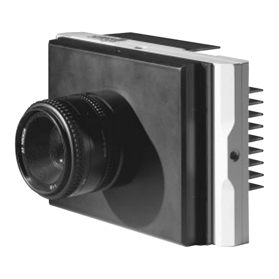
Shutter Cover SenSys Camera with F-mount Adapter and Nikon Lens When you order a SenSys camera, you choose from a range of CCDs that differ in size and grade. All SenSys CCDs are scientific-grade, grades with fewer defects than commercial grades. Scientific-grade CCDs image with better... -
Page 21: Metachrome Ii
Service. Window The SenSys camera has one window in the optical path. The CCD does not have a window. Compared to a multiple-window design, a single window reduces the chance of image degradation due to multiple reflections, stray light, and interference patterns. -
Page 22: Electronics
12-bit data. With a lesser quality signal, the ADC produces data with a lower effective bit depth. The SenSys camera produces an analog signal that uses the full range of the 12-bit ADC (up to 4096 gray levels). Through software, the camera can be set to High Sensitivity (Gain 3), High Dynamic Range (Gain 2), or High Signal to Noise Ratio (Gain 1) detection modes. -
Page 23: Aia Port
CCD reached operating temperature If the ambient temperature is between 0°C and 40°C, the CCD will usually reach operating temperature within 20-40 seconds. If operating temperature is not reached after approximately one minute, call Photometrics Customer Service. SenSys User Manual... -
Page 24: Power Brick
Power Brick The power brick is a switched, multiple-output-voltage supply with a detachable power cord. The camera system is powered on (|) and off (0) by a switch on the brick. More detailed specifications are available in Chapter 6. Specifications. Caution: Connecting or removing a live power cable can damage the camera's electronic components. -
Page 25: Mount Adapters
(optional) SenSys Mount Adapters and Lens Options The SenSys F- and C-mount adapters thread into the camera at a pitch of 32 threads/inch. When the camera is focused, two #6-32 inch socket set screws (two #4-40 inch socket set screws for the C-mount) secure the adapters in place and hold the optical alignment in parfocality. -
Page 26: C-Mount
For specifications, see F-Mount Adapter on page 26. Lenses Photometrics sells lenses that are compatible with the SenSys lens mount adapters. The F-mount lens is compatible with a standard Nikon bayonet mount. The C-mount lens is a standard threaded video mount lens. - Page 27 SenSys User Manual...
-
Page 28: Chapter 5. Troubleshooting
The following issues have corresponding troubleshooting sections in this chapter. Additional issues are covered in the Troubleshooting chapter of the Software Guide. Call Photometrics Customer Service if you have any questions. Error messages are listed in the Error Messages Appendix of the Software Guide. -
Page 29: Camera Shutter Needs Replacing
Caution: Make sure to remove the shutter cover and not the camera back. Removing the camera back will expose the CCD and void your warranty. Shutter Cover 2. Using a #1 Phillips screwdriver, remove the two #4-40 pan head Phillips screws that attach the shutter board. Shutter Board SenSys User Manual... - Page 30 3. Pull the shutter board straight up until it is unplugged from the main board. Then unplug the shutter power connector from the shutter board. Shutter Board Shutter Connector 4. Using a standard screwdriver, remove the four #2-56 slotted binding head screws that secure the shutter to the camera.
-
Page 31: Camera Does Not Focus
Camera Does Not If your SenSys camera is not focusing, find your camera configuration in the Focus following list: • An F-mount adapter is installed on your camera, and you are using an F-mount lens. See the focusing instructions in your imaging software and lens documentation. -
Page 32: Chapter 6. Specifications
Chapter 6. Specifications Camera Weight: 3 lbs without lens or lens mount Width: 4.48 in (113.7 mm) Length: 7.15 in (181.6 mm) Thickness: 3.00 in (76.2 mm) for F-mount; 2.66 in (67.6 mm) for C-mount Window thickness: 1 mm Distance from top of shutter cover to CCD image plane: F-mount Distance C-mount Distance 0400 and 1600 1.05 in (26.7 mm) -
Page 33: F-Mount Camera
F-Mount Camera 3.00 in (76.2 mm) 7.15 in (181.6 mm) F-mount Camera Side View 3.00 in 3.00 in (76.2 mm) (76.2 mm) 4.48 in 4.48 in (113.8 mm) (113.8 mm) F-mount Camera Top View SenSys User Manual... -
Page 34: C-Mount Camera
C-Mount Camera 2.60 in (66.0 mm) 7.15 in (181.6 mm) C-mount Camera Side View 2.60 in (66.0 mm) 4.48 in (113.8 mm) C-mount Camera Top View Chapter 6. Specifications... -
Page 35: F-Mount Adapter
CCD Focal Plane Side View of F-mount (mounted) for KAF 0400 and KAF 1600 1.74 in (44.2 mm) minimum distance Threads at 1.07 in 32 threads/inch (27.2 mm) CCD Focal Plane Side View of F-mount (mounted) for KAF 1400 SenSys User Manual... -
Page 36: C-Mount Adapter
C-Mount Adapter 1.60 in dia. (40.6 mm) 1.00-32 UN Thread Top View of C-mount 1.60 in dia. (40.6 mm) .26 in .96 in dia. (6.6 mm) Threads at (24.5 mm) 32 threads/inch 1.50 in dia. (38.1 mm) Side View of C-mount (unmounted) .63 in (16.0 mm) minimum... -
Page 37: Power Brick
2.25 in (57.1 mm) 6.97 in (177.0 mm) 3.74 in (95.0 mm) The power supply is a +5V DC and ±15V DC brick with 100-240V AC input at 50-60 Hz. The maximum power output is 55 W. SenSys User Manual... -
Page 38: Input/Output Port Pinout
Input/Output Port The input/output port provides information about trigger function and shutter Pinout status. All inputs are pulled up to +5V DC through 10k ohm resistors and filtered with 2200pf ceramic capacitors. Outputs are driven by a 74F374 latch. The numbers on the trigger connector diagram below correspond with the numbers given to the definition of each of the pins. - Page 39 INPUT (6), causing a high level to cause a trigger. (The inputs are internally pulled up, therefore it is recommended to drive them with an open collector driver.) GROUND System digital ground. Any external circuitry intended to interface with the trigger control signals must reference this ground connection. SenSys User Manual...
-
Page 40: Power Port Pinout
Power Port Pinout Power Port Pinout Pin # Signal Name +5V DC +5V DC Ground Ground Ground +15V DC Ground -15V DC Ground Chapter 6. Specifications... -
Page 41: Aia Cable Pinout
VD3- VD13+ VD2- VD12+ VD11+ PIX+ VD10+ VD1- VD9+ VD0- VD8+ VD7+ VD6+ Ground Ground Ground VD5+ VD15- FEN- VD4+ VD14- LEN- VD3+ VD13- VD2+ VD12- VD11- PIX- VD10- VD1+ VD9- VD0+ VD8- VD7- VD6- Ground Ground SenSys User Manual... -
Page 42: Ccd Orientation
CCD Orientation Parallel Camera Front View — KAF 0400 and KAF 1600 CCD Orientation Serial Camera Front View — KAF 1400 CCD Orientation Chapter 6. Specifications... -
Page 43: Ccd Specifications
* Binning must be a minimum of 2 pixels in the parallel and serial direction to reach the maximum ADC signal. 1000 Wavelength (nm) Typical QE Curve (not installed in camera) QE response in the 200-400 nm range can be enhanced with Photometrics’ proprietary Metachrome II coating. SenSys User Manual... -
Page 44: Kaf 1400
* Binning must be a minimum of 2 pixels in the parallel and serial direction to reach the maximum ADC signal. 1000 Wavelength (nm) Typical QE Curve (not installed in camera) QE response in the 200-400 nm range can be enhanced with Photometrics’ proprietary Metachrome II coating. Chapter 6. Specifications... -
Page 45: Kaf 1600
* Binning must be a minimum of 2 pixels in the parallel and serial direction to reach the maximum ADC signal. 1000 Wavelength (nm) Typical QE Curve (not installed in camera) QE response in the 200-400 nm range can be enhanced with Photometrics’ proprietary Metachrome II coating. SenSys User Manual... -
Page 46: Index
(CCD) power port pinout chamber power supply 7–10 description hardware, configuration options orientation help specifications SenSys camera KAF 0400 KAF 1400 KAF 1600 input/output (I/O) port pinout use of thermoelectric cooler input/output (I/O) trigger port cleaning installation camera 5–6... - Page 47 TTL I/O trigger port connecting See input/output (I/O) trigger port description specifications window, in SenSys camera See primary point digitization precautions, for SenSys camera primary point digitization (PPD) readout readout rate repair SenSys camera...
- Page 48 57-054-001 Rev A...
Need help?
Do you have a question about the SenSys and is the answer not in the manual?
Questions and answers