Manitowoc QF0400 Technician's Handbook
Hide thumbs
Also See for QF0400:
- Service manual (150 pages) ,
- Installation, use & care manual (44 pages) ,
- Building instructions (2 pages)
Table of Contents
Advertisement
Quick Links
Advertisement
Chapters
Table of Contents

Related Manuals for Manitowoc QF0400


Summary of Contents for Manitowoc QF0400
- Page 1 Manitowoc Q Model Flake/Chiplet S Model Flake/Nugget Technician’s Handbook This manual is updated as new information and models are released. Visit our website for the latest manual. www.manitowocice.com America’s #1 Selling Ice Machine Part Number 80-1230-9 10/10...
-
Page 3: Safety Notices
Safety Notices As you work on Manitowoc equipment, be sure to pay close attention to the safety notices in this handbook. Disregarding the notices may lead to serious injury and/or damage to the equipment. Throughout this handbook, you will see the following types of safety notices: Warning Text in a Warning box alerts you to a potential... - Page 4 NOTE: Text set off as a Note provides you with simple, but useful, extra information about the procedure you are performing. Read These Before Proceeding: ! Caution Proper installation, care and maintenance are essential for maximum performance and trouble- free operation of your Manitowoc equipment. If you encounter problems not covered by this handbook, do not proceed, contact Manitowoc Foodservice Group.
-
Page 5: Table Of Contents
Table of Contents General Information Model Numbers ..... 13 How to Read a Model Number ..14 Model/Serial Number Location . - Page 6 Exterior Cleaning ....45 Preventative Maintenance Procedure . . 46 QF0400 ..... . . 46 QC0700/QF0800/QF2200/QF2300 . . 48...
- Page 7 Ice Making Sequence of Operation ..105 QF0400/QC0700/QF0800 ..105 QF2200 ......107 QF2300 .
- Page 8 Component Check Procedures QF0400/QC0700/QF0800/QF2200/QF2300 153 Main Fuse ..... . 153 ICE/OFF/CLEAN Toggle Switch ..154 Water Float Valve ....155 Water Level Check .
- Page 9 Gear Box Removal ....210 QF0400 ......210 QC0700/QF0800 .
- Page 10 Charts Cycle Times/24-Hour Ice Production/ Refrigerant Pressure Charts ..233 SN012A/SN020A ....234 QF0400A Stainless Steel Evaporator . 235 QF0400A Bronze Evaporator .
- Page 11 Wiring Diagrams ....265 QF0400 115/60/1 – 230/50/1 ..266 QC0700/QF0800 115/60/1 – 230/50/1 267 QC0700/QF0800 115/60/1 –...
- Page 12 This Page Intentionally Left Blank Part Number 80-1230-9 10/10...
-
Page 13: General Information
General Information Model Numbers Head Section Models Self- Self- Traditional Remote Contained Contained Remote Condensing Air-Cooled Water-Cooled Condenser Unit SN012A (T) SN020A (T) QF0406A SF0406A SN0407W SN0458A SN0459W SF0606A SF0607W SF0696N SN0658A SN0659W SN0698N QC0708A QC0709W QF0806A QF0807W SF0906A SF0907W SF0976C SN0958A SN0959W... -
Page 14: How To Read A Model Number
NOTE: Model numbers ending in 3 indicate a 3-phase unit. Example: RFC12853 * Traditional Remotes - condenser is outside, compressor is inside. The heat is rejected outside. Line set consists of a high pressure discharge line and a high pressure liquid line. Only models ending in “N” use Traditional Remote Condensers. -
Page 15: Model/Serial Number Location
MODEL/SERIAL NUMBER LOCATION These numbers are required when requesting information from your local Manitowoc Distributor, service representative, or Manitowoc Ice, Inc. The model and serial number are listed on the OWNER WARRANTY REGISTRATION CARD. They are also listed on the MODEL/SERIAL NUMBER DECAL affixed to the ice machine. -
Page 16: Q Model & S Model Flake/Chiplet/Nugget Commercial Warranty
Q Model & S Model Flake/Chiplet/Nugget Commercial Warranty Manitowoc Ice, Inc. (hereinafter referred to as the "COMPANY") warrants for a period of twenty four months from the installation date (except as limited below) that new Flake/Chiplet ice machines manufactured by the COMPANY shall be free of... - Page 17 COMPANY within five (5) days from the installation date. Complete the following and retain for your record: Distributor/Dealer Model Number Serial Number Installation Date MANITOWOC ICE 2110 So. 26 St., P.O. Box 1720, Manitowoc, WI 54220 Telephone: 920-682-0161 Fax: 920-683-7585 Web Site - www.manitowocice.com...
-
Page 18: Q Model & S Model Flake/Chiplet/Nugget Residential Warranty
Residential Warranty WHAT DOES THIS LIMITED WARRANTY COVER? Subject to the exclusions and limitations below, Manitowoc Ice, Inc. (“Manitowoc”) warrants to the original consumer that any new ice machine manufactured by Manitowoc (the “Product”) shall be free of defects in material or workmanship for the... - Page 19 WHAT ARE MANITOWOC ICE’S OBLIGATIONS UNDER THIS LIMITED WARRANTY? If a defect arises and Manitowoc receives a valid warranty claim prior to the expiration of the warranty period, Manitowoc shall, at its option: (1) repair the Product at Manitowoc’s cost, including standard...
- Page 20 WHAT IS NOT COVERED? This limited warranty does not cover, and you are solely responsible for the costs of: (1) periodic or routine maintenance, (2) repair or replacement of the Product or parts due to normal wear and tear, (3) defects or damage to the Product or parts resulting from misuse, abuse, neglect, or accidents, (4) defects or damage to the Product or parts resulting from...
- Page 21 VENT HALL ANITOWOC FFILIATES IABLE ONSUMER THER ERSON NCIDENTAL ONSEQUENTIAL PECIAL AMAGES NCLUDING ITHOUT IMITATION ROFITS EVENUE USINESS RISING ANNER ONNECTED RODUCT REACH IMITED ARRANTY THER AUSE HATSOEVER HETHER ASED ONTRACT THER HEORY IABILITY Some states do not allow the exclusion or limitation of incidental or consequential damages, so the above limitation or exclusion may not apply to you.
- Page 22 This Page Intentionally Left Blank Part Number 80-1230-9 10/10...
-
Page 23: Installation
Installation Warning PERSONAL INJURY POTENTIAL Remove all ice machine panels before lifting and installing. Location of Ice Machine The location selected for the ice machine must meet the following criteria. If any of these criteria are not met, select another location. •... -
Page 24: Ice Machine Clearance Requirements
Ice Machine Clearance Requirements Self-Contained SN12/SN20 Water-Cooled* Air-Cooled 24" (61.0 cm) Sides 8" (20.3 cm) Back 5" (12.7 cm) Self-Contained Water-Cooled QF400 Air-Cooled and Remote* Top/Sides 5" (12.7 cm) Back 5" (12.7 cm) SF400/SN450 SF600/SN650 Self-Contained Water-Cooled SF900/SN950 Air-Cooled and Remote* S1200/SN1250 Top/Sides 8"... -
Page 25: Ice Machine Heat Of Rejection
Ice Machine Heat of Rejection Heat of Rejection* Series Ice Machine Air Conditioning SN12/SN20 2,300 QF400 4,000 SF400/SN450 3,400 SF600/SN650 5,300 QF800/QC700 7,800 SF900/SN950 9,000 SF900C/SN950C SF1200/SN1250 16,000 SF1200C/SN1250C QF2200/QF2300 21,000 BTU/Hour Because the heat of rejection varies during the ice making cycle, the figure shown is an average. -
Page 26: Location Of Traditional Remote Units And Remote Condensing Units
Location of Traditional Remote Units and Remote condensing units The location selected for the Remote Units must meet the following criteria. If any of these criteria are not met, select another location. • The air temperature must be at least -20°F (-28.9°C) but must not exceed 120°F (49°C). -
Page 27: Electrical Service
(does not apply in Canada). Warning The ice machine must be grounded in accordance with national and local electrical codes. SN012/SN020/QF0400 115/60/1 ice machines are factory pre-wired with a power cord and 5-15P plug confirmation. SN012/SN020/QF0400 230/50/1 ice machines are factory pre-wired with a power cord, no plug is supplied. -
Page 28: Circuit Ampacity
Self Contained Air-Cooled Max. Fuse/ Voltage Total Circuit Machine Phase Cycle Amps Breaker 115/1/60 10.3 SN012 SN020 230/1/50 115/1/60 QF0400 230/1/50 Voltage Max. Fuse/ Minimum Phase Circuit Circuit Machine Cycle Breaker Amps Air-Cooled 115/1/60 13.7 230/1/50... - Page 29 Voltage Max. Fuse/ Minimum Phase Circuit Circuit Machine Cycle Breaker Amps Air-Cooled 115/1/60 18.9 230/1/50 230/1/60 QC0700/ QF0800 Water-Cooled 115/1/60 17.9 230/1/50 230/1/60 Air-Cooled 230/1/50 230/1/60 SF0900/ SN0950 Water-Cooled 230/1/50 230/1/60 Air-Cooled Head Section SF0900C/ SN0950C 115/1/60 Air-Cooled 230/1/50 230/1/60 SF1200/ SN1250 Water-Cooled...
- Page 30 Max. Voltage Minimum Condensing Fuse/ Phase Circuit Unit Circuit Cycle Amps Breaker RFC0985 Remote Condensing Unit used with 208-230/1/60 SF0900C/ 208-230/1/50 SN0950C Remote Condensing Unit RFC1285 208-230/1/60 used with SF1200C/ 208-230/3/60 SN1250C 208-230/1/50 12.0 Remote Condensing Unit RFC2085 208-230/1/60 15.6 used with QF2200 208-230/3/60...
-
Page 31: Ice Machine Head Section Water Supply And Drains
Ice Machine Head Section Water Supply and Drains POTABLE WATER SUPPLY Local water conditions may require treatment of the water to inhibit scale formation, filter sediment, remove chlorine, and improve taste and clarity. Important If you are installing a Manitowoc water filter system, refer to the Installation Instructions supplied with the filter system for ice making water inlet connections. -
Page 32: Drain Connections
DRAIN CONNECTIONS Follow these guidelines when installing drain lines to prevent drain water from flowing back into the ice machine and storage bin: • Drain lines must have a 1.5 in. (3.8 cm) drop per 5 ft. of run (2.5 cm per meter), and must not create traps. -
Page 33: Installing On A Dispenser
INSTALLING ON A DISPENSER Nugget ice is soft and chewable. This characteristic makes this ice more difficult to dispense. All dispenser manufacturers require a kit be installed for Nugget type ice. Contact the dispenser manufacturer for the correct adapter and nugget dispensing kit for your specific model dispenser. -
Page 34: Line Set Requirements
LINE SET REQUIREMENTS Traditional Remote Units Only Ice Machine Condenser Line Set Head Section RM-20 SN0650 JC0495 RM-35 RM-50 Insulation Discharge Liquid Line Set Line Line Thickness 5/16 in 1/4 in 1/2 in RM20/35/50 (7.9 mm) (7 mm) 12.7 mm QuietQube Remote Condensing Units Only Ice Machine Condensing... - Page 35 • Maximum total amount of tubing is 100’ (30.5 M) • Maximum height condenser or condensing unit can be above ice machine is 35’ (10.7 M) • Maximum distance condenser or condensing unit can be below the ice machine 15’ (4.5 M) •...
- Page 36 This Page Intentionally Left Blank Part Number 80-1230-9 10/10...
-
Page 37: Component Identification
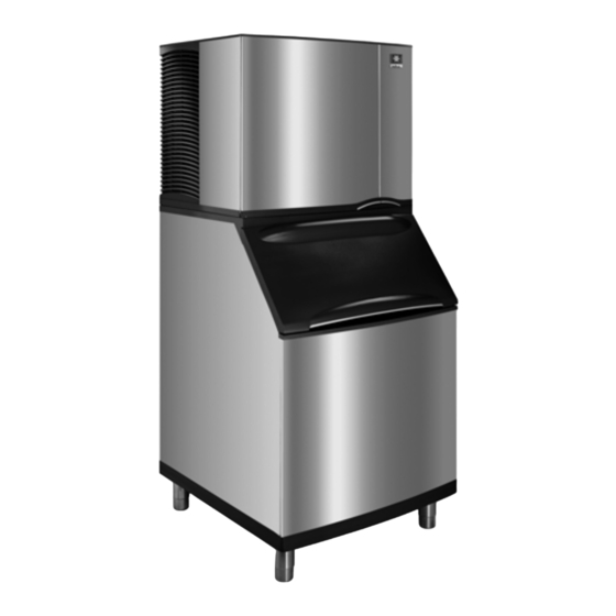
Component Identification QF400 Air-cooled WATER FLOAT VALVE WATER LEVEL PROBES COIL EVAPORATOR CONTROL BOX POTABLE WATER DRAIN GEAR MOTOR / GEAR BOX ICE/OFF/CLEAN ASSEMBLY TOGGLE SWITCH CONDESER FAN/ MOTOR Part Number 80-1230-9 10/10... -
Page 38: Qf800/Qc700 Air & Water-Cooled
QF800/QC700 Air & Water-cooled WATER LEVEL PROBE CLEANING SOLUTION FILL HOLE DUMP VALVE CONDENSER FAN MOTOR ICE CHUTE ICE/OFF/CLEAN TOGGLE SWITCH Part Number 80-1230-9 10/10... -
Page 39: Sf0400/Sn0450/Sf0600/Sn0650/Sf0900/ Sn0950/Sf1200/Sn1250 Air & Water-Cooled
SF0400/SN0450/SF0600/SN0650/SF0900/ SN0950/SF1200/SN1250 Air & Water- cooled COMPRESSOR ELECTRICAL AIR BAFFLE GEAR ENTRANCE MOTOR CONDENSER FAN ICE CHUTE MOTOR WATER INLET WATER RESERVOIR AIR-COOLED CONDENSER EVAPORATOR DRAIN FITTING GEAR BOX DUMP VALVE Part Number 80-1230-9 10/10... - Page 40 GEAR MOTOR ICE CHUTE COVER HALL EFFECT SWITCH WATER RESERVOIR TOGGLE CONTROL BOX CONTROL SWITCH BOARD Part Number 80-1230-9 10/10...
-
Page 41: Sf0600/Sn0650/Sf0900/Sn0950/Sf1200/ Sn1250 Remote & Quietqube Model
SF0600/SN0650/SF0900/SN0950/SF1200/ SN1250 Remote & QuietQube Model COOL VAPOR VALVE QuietQube Only HALL EFFECT SUCTION SWITCH LINE & LIQUID LINE CONTROL WATER INLET DRIER EXPANSION VALVE RECEIVER WATER RESERVOIR GEAR WATER MOTOR DUMP VALVE EVAPORATOR Part Number 80-1230-9 10/10... - Page 42 This Page Intentionally Left Blank Part Number 80-1230-9 10/10...
-
Page 43: Maintenance
Maintenance Maintenance procedures or failures due to a lack of maintenance are not covered by the warranty. Manitowoc Ice Machine Cleaner and Sanitizer are the only products approved for use in Manitowoc ice machines. ! Caution Use the correct Manitowoc approved metal safe Ice Machine Cleaner (part number 000000084) and Sanitizer (part number 94-0565-3). -
Page 44: Manitowoc's Cleaning Technology
Manitowoc’s Cleaning Technology Manitowoc Flake/Nugget Ice Machines allow the initiation and completion of a cleaning cycle at the flip of a switch. This cycle will permit cleaning of all surfaces that come in contact with the water distribution system. Periodic maintenance must be performed that includes sanitizing the bin and adjacent surface areas, which are not contacted by the water distribution system. -
Page 45: Exterior Cleaning
Preventative Maintenance Cleaning Procedure Perform this procedure as often as required for your water conditions: • Allows cleaning the ice machine without removing all of the ice from the bin/dispenser. • Removes mineral deposits from areas that are in direct contact with water during the Freeze cycle (reservoir, evaporator, auger, drain lines). -
Page 46: Preventative Maintenance Procedure
Step 3 Wait about 1 minute or until the dump valve light de-energizes. Lift the front cover on the reservoir and add the proper amount of Manitowoc Ice Machine Cleaner ! Caution Use Manitowoc clear (P/N 000000084) Ice Machine Cleaner only. - Page 47 NOTE: Periodic cleaning must be performed on adjacent surface areas not contacted by the water distribution system. Manitowoc recommends disassembling, cleaning and sanitizing the ice machine and bin/dispenser a minimum of once every six months. Step 5 A. The ice machine may be set to start and finish a cleaning procedure, and then automatically start ice making again.
-
Page 48: Qc0700/Qf0800/Qf2200/Qf2300
Step 3 Remove the 1-1/2 in. plug from the top cover of the water reservoir. Wait about one minute or until the Dump Valve light de-energizes, then add the proper amount of Manitowoc Ice Machine Cleaner and reinstall the plug. ! Caution Use Manitowoc clear (P/N 000000084) Ice Machine Cleaner only. - Page 49 NOTE: Periodic cleaning must be performed on adjacent surface areas not contacted by the water distribution system. Manitowoc recommends disassembling, cleaning and sanitizing the ice machine and bin/dispenser a minimum of once every six months. Step 5 A. The ice machine may be set to start and finish a cleaning procedure, and then automatically start ice making again.
-
Page 50: Sn012/Sn020/Sf0400/Sn0450/Sf0600/ Sn0650/Sf0900/Sn0950/Sf1200/Sn1250
Step 2 Remove the cover from the top of the ice chute. Wait about one minute then add the proper amount of Manitowoc Ice Machine Cleaner and re- install cover. ! Caution Use only Manitowoc approved Ice Machine Cleaner part number 000000084. - Page 51 ADD SOLUTION HERE Step 3 The ice machine will automatically time out a series of flush and rinse cycles, and then stops. This entire cycle lasts approximately 30 minutes. NOTE: Periodic cleaning must be performed on adjacent surface areas not contacted by the water distribution system.
- Page 52 Changing toggle switch position during clean cycle: 1. Less than 60 seconds into Clean cycle - The Clean cycle will end when the toggle switch is moved to the OFF position. 2. More than 60 seconds into Clean cycle - The ice machine will complete the clean cycle.
-
Page 53: Heavily Scaled Procedure
Heavily Scaled Procedure QF0400 Procedure to Clean Heavily Scaled Ice Machines Step 1 Remove all ice from the bin. Step 2 Remove front and top covers and set the toggle switch to the OFF position. Step 3 Disconnect water supply line at float valve quick disconnect by depressing stainless steel lever. -
Page 54: Qc0700/Qf0800/Qf2200/Qf2300
QC0700/QF0800/QF2200/QF2300 Procedure to Clean Heavily Scaled Ice Machines Step 1 Remove all ice from the bin. Step 2 Remove front and top covers and set the toggle switch to the OFF position. Step 3 Disconnect water supply line at float valve quick disconnect by depressing stainless steel lever. -
Page 55: Sn012/Sn020/Sf0400/Sn0450/Sf0600/ Sn0650/Sf0900/Sn0950/Sf1200/Sn1250
SN012/SN020/SF0400/SN0450/SF0600/SN0650/ SF0900/SN0950/SF1200/SN1250 Procedure to Clean Heavily Scaled Flake/Nugget Ice Machines Ice machines that are heavily scaled or have not been cleaned on a regular basis will need to run this Procedure. Failure to do so may result in binding of the auger as the lime scale releases from the auger and evaporator barrel. - Page 56 ADD SOLUTION HERE Step 1 Turn on the water supply to the ice machine. Important Leave cleaner/water solution evaporator for a minimum of 4 hours. Step 2 Move the toggle switch to the ICE position. The compressor will energize and produce ice with the cleaning solution.
-
Page 57: Cleaning And Sanitizing Procedure
Step 3 Wait about 1 minute or until the dump valve light de-energizes. Lift the front cover on the reservoir and add the proper amount of Manitowoc Ice Machine Cleaner Amount of Cleaner Model... - Page 58 Step 5 Disconnect water supply line at float valve quick disconnect by depressing stainless steel lever. Step 6 Mix 2 oz. (60 ml) of Manitowoc Ice Machine Sanitizer with 3 gal. (11 L) of cool water. Amount of Model Sanitizer/Water 2 oz.
- Page 59 Step 9 After the entire sanitizer/water solution has been added to the reservoir, reconnect the water supply line at the float valve quick disconnect. The ice machine will continue to freeze and discharge the sanitizing solution into the bin. Allow the cycle to run for ten minutes to remove all sanitizing solution from the water reservoir.
-
Page 60: Qc0700/Qf0800/Qf2200/Qf2300
Step 7 Wait 45 seconds until the Dump Valve light de-energizes and the Water Level Probe light energizes. Add the proper amount of Manitowoc Ice Machine Cleaner to the water reservoir. Amount of Cleaner... - Page 61 Step 11 Mix 2 oz. (60 ml) of Manitowoc Ice Machine Sanitizer with 3 gal. (11 L) of cool water. Amount of Model Sanitizer/Water QF0800/QC0700/QF2200/ 2 oz. (60 ml) QF2300 mixed with 3 gal. (11 L) cool water Step 12 To start the sanitizing procedure, move the toggle switch to the ICE position.
-
Page 62: Sn012/Sn020/Sf0400/Sn0450/Sf0600/ Sn0650/Sf0900/Sn0950/Sf1200/Sn1250
SN012/SN020/SF0400/SN0450/SF0600/SN0650/ SF0900/SN0950/SF1200/SN1250 Cleaning & Sanitizing Procedure Ice machines that are heavily scaled or have not been cleaned on a regular basis will need to run the Heavily Scaled Cleaning Procedure before this one. Failure to do so may result in binding of the auger as the lime scale releases from the auger and evaporator barrel. - Page 63 Step 6 Refer to chart and premix the correct solution of cleaner and cool water for your model ice machine. Amount of Cleaner Amount of Model Water Part Number 000000084 SN12 SN20 2 oz (60 ml) 32 oz (1 liter) SF0400 SN0450 2 oz (60 ml) 32 oz (1 liter)
- Page 64 Step 16 Refer to chart and premix the correct solution of sanitizer and cool water for your model ice machine. Amount of Sanitizer Model Part Number Amount of Water 94-0565-3 SN12 SN20 SF0400 SN0450 SF0600 2 ounces (60 ml) 3 gallons (11.4L) SN0650 SF0900 SN0950...
-
Page 65: Component Disassembly For Cleaning And Sanitizing
Component Disassembly For Cleaning And Sanitizing Warning Disconnect electric power to the ice machine at the electric switch box before proceeding. Warning Wear rubber gloves and safety goggles (and/or face shield) when handling Ice Machine Cleaner or Sanitizer. ! Caution Do not mix Cleaner and Sanitizer solutions together. -
Page 66: Qf400
QF400 Removal of Parts for Cleaning and Sanitizing Water Level Probe Removal 1. Place the toggle switch in the OFF position, turn off the water supply and disconnect electrical power to the ice machine. 2. Disconnect water supply line at float valve quick disconnect by depressing stainless steel lever. - Page 67 Float Valve Removal 1. Place the toggle switch in the OFF position, turn off the water supply and disconnect electrical power to the ice machine. 2. Disconnect water supply line at float valve quick disconnect by depressing stainless steel lever. 3.
- Page 68 Ice Diverter Removal 1. Place the toggle switch in the OFF position, turn off the water supply and disconnect electrical power to the ice machine. 2. Remove thumbscrews and lift panel forward. 3. Remove bin level sensor from white plastic panel. 4.
- Page 69 Bin Door Removal Door removal allows easier access for cleaning and sanitizing. 1. Disconnect the electrical power to the ice machine and remove ice from bin. 2. Grasp the rear of the bin door and pull bin door forward approximately 5”. 3.
- Page 70 Cabinet Removal 1. Remove all ice from bin and disconnect power. 2. Remove thumbscrews and evaporator panel. 3. Remove three screws from the bottom of the left and right side of cabinet. 4. Remove nine screws from back panel. 5. Disconnect drain line clamp. 6.
-
Page 71: Qc0700/Qf0800/Qf2200/Qf2300
QC0700/QF0800/QF2200/QF2300 Removal of Parts for Cleaning or Sanitizing Water Level Probe Removal 1. Place the toggle switch in the OFF position, turn off the water supply and disconnect electrical power to the ice machin.e. 2. Disconnect water supply line at float valve quick disconnect by depressing stainless steel lever. - Page 72 Water Reservoir Cover Removal 1. Place the toggle switch in the OFF position, turn off the water supply and disconnect electrical power to the ice machine. 2. Remove water level probes. 3. Remove water float valve coil. A. Depress coil and rotate 1/4 turn counterclockwise.
- Page 73 Water Reservoir Cover Removal QF2200/QF2300 1. Place the toggle switch in the OFF position, turn off the water supply and disconnect electrical power to the ice machine. 2. Remove water level probes. 3. Remove water float valve coil. 4. Depress coil and rotate 1/4 turn counterclockwise. 5.
- Page 74 Float Valve Removal 1. Place the toggle switch in the OFF position, turn off the water supply and disconnect electrical power to the ice machine. 2. Disconnect water supply line at float valve quick disconnect by depressing stainless steel lever. 3.
- Page 75 Water Reservoir Removal 1. Place the toggle switch in the OFF position and turn off the water supply to the ice machine at the water service valve. 2. Disconnect water supply line at float valve quick disconnect by depressing stainless steel lever. 3.
- Page 76 Ice Chute Removal (QF0800/QC0700) 1. Follow steps to remove float reservoir. 2. The ice chute and ice chute grommet will be removed as a unit. Pull forward on the top of the ice chute, and slide the ice chute and grommet off the end of the evaporator spout.
- Page 77 QF2200/QF2300 1. Place the toggle switch in the OFF position, turn off the water supply and disconnect electrical power to the ice machine. 2. Remove ice chute retaining clamp from top of evaporator. 3. Remove vinyl hose from ice chute spout. 4.
- Page 78 SF400/SN450/SF600/SN650/SF900/SN950/SF1200/ SN1250 Removal of Parts for Cleaning or Sanitizing 1. Remove front, side and top panels. 2. Perform the cleaning and sanitizing procedures. 3. Run the ice machine in the freeze cycle for 5 minutes, then place the toggle switch in the OFF position.
- Page 79 7. Disconnect the water supply. 8. Reconnect the main power supply to the ice machine. 9. Place toggle switch in the clean position for 30 seconds to drain water from reservoir, then move the toggle switch to the Off position. 10.
- Page 80 11. Lift out ice damper. 12. Lift out ice strainer ramp. Part Number 80-1230-9 10/10...
- Page 81 13. Loosen ice chute hose clamp. 14. Disconnect ice chute drain. ICE CHUTE DRAIN AND HOSE CLAMP 15. Lift up on ice chute to remove. Part Number 80-1230-9 10/10...
- Page 82 16. The ice chute can be cleaned in place. If complete removal is desired use a phillips screwdriver to remove the Hall Effect Switch assembly from the ice chute. REMOVE SCREW 17. Remove ice chute collar and tube by lifting straight up.
- Page 83 18. Remove water reservoir cover by pushing up on cover to snap off. The water reservoir can be cleaned in place. Part Number 80-1230-9 10/10...
-
Page 84: Sn012/Sn020
SN012/SN020 Removal of Parts for Cleaning or Sanitizing 1. Turn off water supply to ice machine. 2. Place toggle switch in the clean position for 30 seconds to drain water from reservoir, then move toggle switch to Off position. 3. Run dispenser to transfer all ice from the bin to a container. - Page 85 6. Remove front cover. A. Lift up on front cover. B. Pull forward to disengage keyhole slots. 7. Remove side panels. Part Number 80-1230-9 10/10...
- Page 86 8. Remove ice chute cover A. Turn the two thumbscrews 1/4 turn. B. Lift to remove cover. LOOSEN SCREWS Part Number 80-1230-9 10/10...
- Page 87 9. Lift out ice damper. Part Number 80-1230-9 10/10...
- Page 88 10. Lift out ice strainer ramp. Part Number 80-1230-9 10/10...
- Page 89 11. Turn ice wiper counterclockwise to remove. Part Number 80-1230-9 10/10...
- Page 90 12. Loosen ice chute hose clamp. 13. Disconnect ice chute drain. ICE CHUTE ICE CHUTE DRAIN HOSE CLAMP Part Number 80-1230-9 10/10...
- Page 91 14. Lift up on ice chute to remove. The ice chute must be removed before the bin cover can be removed. Part Number 80-1230-9 10/10...
- Page 92 15. The ice chute can be cleaned in place. If complete removal is desired use a phillips screwdriver to remove the Hall Effect Switch assembly from the ice chute. REMOVE SCREW Part Number 80-1230-9 10/10...
- Page 93 16. Remove three thumbscrews, then remove bin cover. REMOVE THUMBSCREWS Part Number 80-1230-9 10/10...
- Page 94 17. Remove agitator bar. • SN012 - Remove the thumbscrew and lift off. • SN020 - Unscrew the upright agitator bar. NOTE: Bar must be reassembled by inserting front edge into the paddle wheel, then lowering the back edge (rounded 90 angle) to prevent water leakage into the compressor compartment.
- Page 95 18. Remove ice deflector. A. Remove the two thumbscrews. B. Lift the ice deflector out. REMOVE THUMBSCREW Part Number 80-1230-9 10/10...
- Page 96 19. Remove ice dispensing wheel by lifting straight out. Part Number 80-1230-9 10/10...
- Page 97 20. Water Reservoir Cover Removal A. Push up on cover to snap off. Part Number 80-1230-9 10/10...
-
Page 98: Water Dump Valve - All Models
WATER DUMP VALVE - ALL MODELS The water dump valve normally does not require removal for cleaning. To determine if removal is necessary: 1. Set the toggle switch to OFF. 2. Watch the water float valve. If the dump valve is leaking the float will continue to add water in the Off cycle. - Page 99 4. Remove the tubing from the dump valve by twisting the clamps off. 5. Remove the valve body from mounting bracket by twisting counterclockwise. SPRING COIL NYLON WASHER PLUNGER DIAPHRAM MOUNTING BRACKET VALVE BODY Dump Valve Disassembly Part Number 80-1230-9 10/10...
-
Page 100: Cleaning The Condenser
CLEANING THE CONDENSER Warning Disconnect electric power to the ice machine at the electric service switch before cleaning condenser. The condenser fins are sharp. Use care when cleaning them. Air-Cooled Condenser A dirty condenser restricts airflow, resulting in excessively high operating temperatures. This reduces ice production and shortens component life. - Page 101 Water-Cooled Condenser and Water Regulating Valve Symptoms of restrictions in the condenser water circuit include: • Low ice production • High water consumption • High operating temperatures • High operating pressures If the ice machine is experiencing any of these symptoms, the water-cooled condenser and water regulating valve may require cleaning due to scale build-up.
-
Page 102: Removal From Service/Winterization
Removal from Service/Winterization GENERAL Special precautions must be taken if the ice machine is to be removed from service for an extended period of time or exposed to ambient temperatures of 32°F (0°C) or below. ! Caution If water is allowed to remain in the ice machine in freezing temperatures, severe damage to some components could result. -
Page 103: Water-Cooled Ice Machines
WATER-COOLED ICE MACHINES 1. Perform steps 1-6 under “Self-Contained Air- Cooled Ice Machines.” 2. Disconnect the incoming water and drain line from the water-cooled condenser. 3. Insert a large screwdriver between the bottom spring coils of the water regulating valve. Pry upward to open the valve. - Page 104 This Page Intentionally Left Blank Part Number 80-1230-9 10/10...
-
Page 105: Ice Making Sequence Of Operation
Operation Ice Making Sequence of Operation QF0400/QC0700/QF0800 Ice Making Sequence of Operation PRIOR TO START-UP When the toggle switch is placed in the “ice” position the following must occur prior to starting an ice making cycle. • The bin level probe must be open (bin level light off). - Page 106 AUTOMATIC SHUT-OFF 3A. Ice Run Out Ice will build up in the bin until it contacts the bin level probe. After ice contacts the bin level probe for 30 continuous seconds the compressor de-energizes. To allow excess ice to run out, the gear motor and the water float valve solenoid remain energized for an additional 4 minutes, then de-energize.
-
Page 107: Qf2200
QF2200 Ice Making Sequence of Operation PRIOR TO START-UP When the toggle switch is placed in the “ice” position the following must occur prior to starting an ice making cycle. A. The bin level probe must be open (bin level light off). - Page 108 Remote Condensing Unit 3. Freeze When the refrigerant pressure is high enough, the low- pressure control closes. Closing the low pressure control energizes the contactor coil and the compressor starts. The compressor increases the refrigerant pressure, the fan cycling control closes and the condenser fan motor starts.
- Page 109 Flush Sequence in the “ICE” Position After the ice machine has run for 100 hours the ice machine will stop making ice and perform a flush sequence. The flush sequence will remove minerals that have settled in the bottom of the evaporator. The entire flush sequence lasts approximately 11 minutes, after which the ice machine automatically resumes ice making and the 100 hour counter in the control board...
- Page 110 Energized Parts QF2200 Control Relays Sensors Water Gear Sequence Duration Liquid Temperature Float Level Level Motor Line Dump Gear Sensor Valve Probe Probe Speed Solenoid Valve Motor Coil Valve Sensing Sensing for Start-Up Sensing Not Sensing for No Ice Gear Motor 1A.
- Page 111 Energized Parts (Continued) QF2200 Control Relays Sensors Water Gear Sequence Duration Liquid Temperature Float Level Level Motor Line Dump Gear Sensor Valve Probe Probe Speed Solenoid Valve Motor Coil Valve Sensing Not Sensing 3B. Drain Sensing Not Sensing for for Gear Evaporator Water Temperature...
-
Page 112: Qf2300
QF2300 Ice Making Sequence of Operation PRIOR TO START-UP When the toggle switch is placed in the “ice” position the following must occur prior to starting an ice making cycle. A. The bin level probe must be open (bin level light off). - Page 113 AUTOMATIC SHUT-OFF 3A. Ice Run Out Ice will build up in the bin until it contacts the bin level probe. After ice contacts the bin level probe for 30 continuous seconds the liquid line solenoid valve, equalization valve, and compressor de-energize. To allow excess ice to run out, the gear motor and the water float valve solenoid remain energized for an additional 4 minutes, then de-energize.
- Page 114 Energized Parts QF2300 Control Relays Sensors Water Gear Sequence Duration Liquid Line Float Level Level Motor Solenoid Valve/ Dump Gear Valve Probe Probe Speed Equalization Valve/ Valve Motor Coil Compressor Sensing Sensing for Start-Up Sensing No Ice Gear Motor 1A. Water Flush Seconds Water Level Contact...
- Page 115 Energized Parts (Continued) QF2300 Control Relays Sensors Water Gear Sequence Duration Liquid Line Float Level Level Motor Solenoid Valve/ Dump Gear Valve Probe Probe Speed Equalization Valve/ Valve Motor Coil Compressor Not Sensing 3B. Drain Sensing Ice Sensing for Gear Evaporator (90 Sec.) Contact...
-
Page 116: Sn012/Sn020/Sf0400/Sn0450/Sf0600/ Sn0650/Sf0900/Sn0950/Sf1200/Sn1250 Nugget/Flake Machines
SN012/SN020/SF0400/SN0450/SF0600/SN0650/ SF0900/SN0950/SF1200/SN1250 NUGGET/FLAKE MACHINES Ice Making Sequence of Operation PRIOR TO STARTUP When the toggle switch is placed in the ICE position the following must occur in the listed order before ice making will start. • The 5 minute delay period must be expired. The delay period starts upon application of power or a change in toggle switch position. - Page 117 AUTOMATIC SHUTOFF When the ice damper is held open by ice, the gearmotor, compressor and condenser fan de- energize. The five minute delay period starts to time out. The ice machine will remain off until the 5 minute delay period expires and the ice damper closes. RESTART AFTER AUTOMATIC SHUTOFF The 5 minute delay period must be expired.
- Page 118 Control Board Features FLUSH CYCLE After the ice machine has completed 50 hours of run time a flush sequence will start. This cycle will drain and refill the evaporator to remove minerals that have settled to the bottom of the evaporator. The flush sequence lasts approximately 21 minutes, after which the ice machine will reset the 50 hour counter and automatically start ice making again.
-
Page 119: Energized Parts
ENERGIZED PARTS S Model Nugget/Flake Machines Contactor Dump Gear Sequence Ice Damper Duration Coil Valve Motor Initial Start-Up The 5 minute delay must expire Closed Immediate first Moves to Verify Until Ice Holds Damper Freeze Cycle Ice Production Open Automatic Shut-Off Open Until Damper Closes Restart... - Page 120 This Page Intentionally Left Blank Part Number 80-1230-9 10/10...
-
Page 121: Troubleshooting
Troubleshooting SafeGuard Feature The ice machine will stop when conditions arise that would cause major component failure. Standby Mode The first time a failure occurs, the ice machine de- energizes and initiates a Standby Mode. The ice machine will remain off for 60 minutes, then automatically restart to see if the problem reoccurs. - Page 122 Reset Procedure 1. Move the ICE/OFF/CLEAN toggle switch to OFF. A. If a safeguard feature has stopped the ice machine, it will restart after a short delay. Proceed to Step 2. B. If the ice machine does not restart, see “Ice Machine Does Not Operate.”...
-
Page 123: Qf0400/Qc0700/Qf0800/Qf2200/Qf2300
QF0400/QC0700/QF0800/QF2200/QF2300 SafeGuards • No Water • Gear Motor Speed is Incorrect • Discharge line temp. is too high or low during the freeze cycle. NO WATER SAFEGUARD During the Freeze cycle if the water level probe opens or remains open for more than 90 continuous seconds*, the ice machine: 1. - Page 124 The SafeGuard will be automatically erased from memory and the Water Level Probe light will not flash. No Water Checklist Possible Problem List Corrective Action List No water Restore water supply. Quick disconnect removed Restore water supply. from water float valve Water float valve screen Clean screen.
-
Page 125: Gear Motor Speed
GEAR MOTOR SPEED QF0400/QC0700/QF0800/QF2200/QF2300 Anytime the motor speed sensor detects the motor speed (RPM) is below the minimum range for 3 continuous seconds, the ice machine will: 1. De-energize the compressor and/or gear motor. 2. Continuously flash the Gear Motor Speed light. - Page 126 Gear Motor Speed Checklist QF0400/QC0700/QF0800/QF2200/QF2300 Possible Problem List Corrective Action List Low water pressure Verify water pressure is between 20 and 80 psig. Defective motor speed Replace motor speed sensor sensor. Defective motor Replace motor. Defective coupler Replace coupler. Defective evaporator/auger...
-
Page 127: Temperature Is Too High Or Too Low
TEMPERATURE IS TOO HIGH OR TOO LOW QF0400/QC0700/QF0800 The temperature sensor (thermistor) is mounted on the compressor discharge line. The temperature sensor provides input to the control board. The control board monitors the temperature anytime the compressor is energized. If the thermistor detects 245°F or higher for 15 continuous seconds: 1. - Page 128 Discharge line temperature normal: The ice machine continues to make ice. Discharge line temperature below 155°F after 30 minutes of run time: The ice machine will start another 60-minute Standby Mode. If the discharge line temperature drops below 155°F for 3 continuous minutes during 7 consecutive cycles the ice machine will start a SafeGuard Mode.
- Page 129 Temperature Sensor Checklist QF0400/QC0700/QF0800 Possible Problem List Corrective Action List Thermistor is not properly Insulate thermistor. insulated Thermistor loose Secure thermistor to discharge line. Thermistor mounted in the Position thermistor on wrong location discharge line 6 in. from compressor discharge port.
-
Page 130: Qf2200 Only - Temperature Is Too High Or Low
QF2200 ONLY - TEMPERATURE IS TOO HIGH OR The temperature sensor (thermistor) is mounted on the liquid line. The temperature sensor provides input to the control board. The control board monitors the temperature anytime the liquid line solenoid valve is energized. - Page 131 If the liquid line temperature drops below 30°F for 3 continuous minutes during 7 consecutive cycles the ice machine will start a SafeGuard Mode. During the SafeGuard Mode the “Disch Temp” light will continually flash to indicate a Safeguard Mode. The ice machine remains off until: •...
-
Page 132: Sn012/Sn020/Sf0400/Sn0450/Sf0600/ Sn0650/Sf0900/Sn0950/Sf1200/Sn1250
SN012/SN020/SF0400/SN0450/SF0600/ SN0650/SF0900/SN0950/SF1200/SN1250 SafeGuards • No Water • No Ice Production NO WATER The water sensing switch opens for more than 30 seconds. Operation When the float switch is open at initial start-up the ice machine will wait for the switch to close before starting. -
Page 133: No Ice Production
NO ICE PRODUCTION SN012/SN020/SF0400/SN0450/SF0600/SN0650/ SF0900/SN0950/SF1200/SN1250 The ice damper did not open and close at least once every 90 seconds in the freeze cycle. OPERATION During the first 8 minutes of operation: The control board must see the ice damper open/close at least once. - Page 134 Reset Procedure Move the ICE/OFF/CLEAN toggle switch from OFF to ICE or disconnect and reapply power to the ice machine. Part Number 80-1230-9 10/10...
-
Page 135: Diagnosing An Ice Machine That Will Not Run
Diagnosing an Ice Machine That Will Not QF0400/QC0700/QF0800/QF2200/QF2300 Diagnosing An Ice Machine That Will Not Run Warning High (line) voltage is applied to the control board (terminals #21 and #23) at all times. Removing control board fuse or moving the toggle switch to OFF will not remove the power supplied to the control board. -
Page 136: Rfc0985/Rfc1285/Rfc2085/Rfc2385 Diagnosing A Condensing Unit That Will Not Run
RFC0985/RFC1285/RFC2085/RFC2385 DIAGNOSING A CONDENSING UNIT THAT WILL NOT RUN If the ice machine water pump is not energized refer to “Ice Machine Head Section Will Not Run”. 1. Verify primary voltage is supplied to ice machine condensing unit and the fuse/circuit breaker is closed. -
Page 137: Qf0400/Qc0700/Qf0800/Qf2200/Qf2300 Operational Problem Checklist
QF0400/QC0700/QF0800/QF2200/QF2300 OPERATIONAL PROBLEM CHECKLIST Problem Possible Cause To Correct Ice machine does not operate. No electrical power to the ice machine. Replace the fuse/reset the breaker/turn on the main switch/plug power cord into receptacle. Control board fuse open. ICE/OFF/CLEAN toggle switch set improperly. - Page 138 Problem Possible Cause To Correct Ice machine stops, and can be restarted by The SafeGuard feature is stopping the ice moving the toggle switch to OFF and back to Refer to “SafeGuard Modes”. machine. ICE. Ice quality is poor. Test the quality of the incoming water and Poor incoming water quality.
- Page 139 Problem Possible Cause To Correct Low ice capacity. Water float valve filter screen is dirty. Remove and clean the filter screen. Incoming water supply is shut off. Open the water service valve. Water float valve stuck open or leaking. Remove the water float valve and clean it. The condenser is dirty.
-
Page 140: Sn012/Sn020/Sf0400/Sn0450/Sf0600/ Sn0650/Sf0900/Sn0950/Sf1200/Sn1250
SN012/SN020/SF0400/SN0450/SF0600/SN0650/ SF0900/SN0950/SF1200/SN1250 Diagnosing An Ice Machine That Will Not Run Warning High (line) voltage is applied to the control board (terminals #39 and #90) at all times. Removing control board fuse or moving the toggle switch to OFF will not remove the power supplied to the control board. - Page 141 Ice Machine Will Not Run IMPORTANT Power Supplied to Plug In Ice Machine, A Five Minute Delay Initiates After The Problem Is Ice Machine? Reset Breaker Corrected. This Delay Must Expire Before The Ice Machine Will Start. Reset Control Board, Disconnect And Reconnect Line Voltage...
- Page 142 IMPORTANT A Five Minute Delay Initiates After The Problem Is Corrected. This Delay Must Expire Before The Ice Power At Machine Will Start. Refer To High Pressure Cutout Terminals Specifications. #90 & #39? Disconnect HES #2 Flake/Nugget Control Replace Control From Control Board.
- Page 143 IMPORTANT Reservoir Full Of A Five Minute Delay Initiates After The Problem Is Restore Water Supply Water? Corrected. This Delay Must Expire Before The Ice Machine Will Start. Float Switch Light Refer To Float Switch Diagnostics Damper Door Install/Close Damper Door Closed?
- Page 144 IMPORTANT Refer To Hall A Five Minute Delay Initiates After The Problem Is HES #1 Light Corrected. This Delay Must Expire Before The Ice Effect Switch Energized? Machine Will Start. Diagnostics Hes # 2 Light Energized? Toggle Switch Functions? (If The Toggle Switch Energizes And Refer to Toggle De-Energizes The BLue Light, The Switch Diagnostics...
- Page 145 IMPORTANT 5 Minute Delay Wait For Delay To Expire, A Five Minute Delay Initiates After The Problem Is Expired? Then Refer To SafeGuards Corrected. This Delay Must Expire Before The Ice Machine Will Start. Refer to Gearmotor Control Board Fuse Compresor Energizes? Diagnostics Refer to...
-
Page 146: Refrigeration Diagnostics
Refrigeration Diagnostics BEFORE BEGINNING SERVICE Ice machines may experience operational problems only during certain times of the day or night. A machine may function properly while it is being serviced, but malfunctions later. Information provided by the user can help the technician start in the right direction, and may be a determining factor in the final diagnosis. -
Page 147: Water System Checklist
WATER SYSTEM CHECKLIST A water-related problem could cause component misdiagnosis. Water system problems must be identified and eliminated prior to replacing other components. Possible Problem List Corrective Action List Water area (evaporator) is Clean as needed. dirty. Install a water regulator Water inlet pressure not valve or increase the water between 20 and 80 psig. -
Page 148: Ice Production/Quality Check
ICE PRODUCTION/QUALITY CHECK QUALITY CHECK Ice quality will vary with ambient and water temperatures, and is measured by the amount of excess water in the ice. An easy test is to squeeze a handful of ice. High quality ice releases only a small amount of water. -
Page 149: Analyzing Discharge Pressure
ANALYZING DISCHARGE PRESSURE 1. Determine the ice machine operating conditions: Air temperature entering condenser Air temperature around ice machine Water temperature entering water reservoir 2. Refer to 24-Hour Ice Production/Refrigeration Pressure Chart for ice machine being checked. Use the operating conditions determined in step 1 to find the published normal discharge pressures and compare to actual discharge pressure readings. - Page 150 Discharge Pressure Low Checklist Problem Cause Improper Refer to “Installation/Visual Inspection installation Checklist.” Improper Undercharged refrigerant Wrong type of refrigerant charge Low ambient temperature Non-Manitowoc components in system High side refrigerant lines/component restricted (before mid-condenser) Suction pressure is too low and affecting discharge pressure.
-
Page 151: Analyzing Suction Pressure
ANALYZING SUCTION PRESSURE NOTE: Analyze discharge pressure before analyzing suction pressure. High or low discharge pressure may be causing high or low suction pressure. Suction Pressure High Checklist Problem Cause Improper Refer to “Installation/Visual Inspection installation Checklist.” Discharge pressure is too high and is Discharge affecting suction pressure. -
Page 152: Suction Pressure Low Checklist
Suction Pressure Low Checklist Problem Cause Improper Refer to “Installation/Visual Inspection installation Checklist.” Discharge Discharge pressure is too low and is pressure affecting suction pressure. Refer to “Discharge Pressure Low Checklist.” Improper Undercharged refrigerant Wrong type of refrigerant charge Other Non-Manitowoc components in system Restricted/plugged liquid line drier Restricted/plugged tubing in suction side of... -
Page 153: Component Check Procedures
Component Check Procedures QF0400/QC0700/QF0800/QF2200/QF2300 MAIN FUSE FUNCTION The control board fuse stops ice machine operation if electrical components fail, causing high amp draw. SPECIFICATIONS The main fuse is 250 Volt, 10 amp, time delay. Warning High (line) voltage is applied to the control board at all times. -
Page 154: Ice/Off/Clean Toggle Switch
ICE/OFF/CLEAN TOGGLE SWITCH QF0400/QC0700/QF0800/QF2200/QF2300 FUNCTION The switch is used to place the ice machine in ICE, OFF or CLEAN mode of operation. SPECIFICATIONS Single-pole, double-throw switch. The switch is connected into a varying low DC voltage circuit. CHECK PROCEDURE NOTE: Because of a wide variation in DC voltage, it is not recommended that a volt meter be used to check toggle switch operation. -
Page 155: Water Float Valve
WATER FLOAT VALVE QF0400/QC0700/QF0800/QF2200/QF2300 FUNCTION The float valve maintains correct water level during the Freeze cycle. It allows the evaporator to drain completely during the Automatic Shut-Off cycle. CHECK PROCEDURE 1. Verify water is supplied to the float valve, the water inlet screen is clean, and the float and float arm are free moving. -
Page 156: Water Level Check
WATER LEVEL CHECK QF0400/QC0700/QF0800/QF2200/QF2300 The float valve maintains the correct water level. The water level must allow the water level probes to maintain water contact throughout the Freeze cycle. The water level is factory set and normally will not require adjustment. Check the water level during the Freeze cycle. -
Page 157: Bin Level Probe Diagnostics
BIN LEVEL PROBE DIAGNOSTICS QF0400/QC0700/QF0800/QF2200/QF2300 FUNCTION The bin level probe shuts off the ice machine after the bin fills with ice. To start ice making, the bin level probe must be open (Bin Level light off). If the probe is closed (Bin Level... - Page 158 2. Disconnect bin level probe from control board and check continuity (ohms) from the female connector to the bin level probe. CHECK FOR CONTINUITY CONNECTOR TO PROBE. Continuity Cause Replace bin level probe. Go to step 3. Part Number 80-1230-9 10/10...
- Page 159 3. Remove bin level probe from ice chute and clean with Manitowoc Ice Machine Cleaner and Sanitizer. Rinse well with fresh water, reinstall and monitor the Bin light. Control Board Cause Bin Level Light Bin level probe needed cleaning. Flashes Go to step 4.
- Page 160 Bin Level Probe Closed or Shorted The ice machine will not start and the Bin Level light is energized continuously. 1. Verify ice is not in contact with bin level probe. 2. Disconnect bin level probe wire from the control board.
-
Page 161: Water Level Probes
WATER LEVEL PROBES QF0400/QC0700/QF0800/QF2200/QF2300 FUNCTION The water level probe protects the compressor if water is not detected. Water contacting the probes will complete the circuit and energize the Water Level Probe light. There are two water level probes; one probe is connected to the circuit board and one probe is connected to the ice machine ground. - Page 162 Water Level Probe Closed or Shorted (Ice machine will continue to run.) If the ice machine runs out of water with the water level probe shorted, the ice machine will initiate an Automatic Shut-Off cycle and flash the Temperature light. (Refer to “High or Low Temperature SafeGuard”...
- Page 163 4. Disconnect water level probe from control board. Install jumper from control board “water level” terminal to ground. 5. Move the toggle switch from ICE to OFF to ICE position. Wait 45 seconds, then monitor the Water Level Probe light. Step 5 Jumper “water level”...
- Page 164 Water Level Probe Closed or Shorted 1. Disconnect the water level probe from the control board. 2. Move the toggle switch to the ICE position, wait 45 seconds and then monitor the Water Level Probe light. Step 2 Disconnect water level probe from control board “water level”...
-
Page 165: Motor Speed Sensor
MOTOR SPEED SENSOR QF0400/QC0700/QF0800/QF2200/QF2300 FUNCTION The motor speed sensor verifies that the gearbox motor is rotating at the correct speed. FAILURE MODES Motor Speed Sensor Open or Disconnected (Ice machine will not start.) Performs initial start-up procedure. Ten to 15 seconds... - Page 166 4. Count coupling revolutions for 2 minutes. 5. Divide coupling revolutions by 2 (example: 31 coupling revolutions ÷ 2 = 15-1/2 RPM). Minimum revolutions per minute: QF0400 = 9 RPM QC0700 = 15 RPM QF0800 = 15 RPM QF2200/QF2300 = 11.6 RPM...
-
Page 167: Temperature Sensor
When a temperature is sensed that is above or below the correct temperature range, the ice machine de-energizes. TEMPERATURE RANGES: QF0400/QC0700/QF0800 155°F to 255°F (68°C to 124°C) QF2200 30°F to 123°F (-1°C to 51°C) Specifications 10,000 Ohms at 77°F (25°C) ! Caution Use only Manitowoc thermistors. - Page 168 3. With the ice machine running, verify that the temperature of the refrigeration line (step 2) corresponds to the thermistor resistance reading (step 1) as stated in the temperature/resistance chart. Temperature/Resistance Chart As the temperature rises at the thermistor block, the resistance drops.
-
Page 169: Qf2200 Only
QF2200 Only LOW PRESSURE CUT-OUT CONTROL RFC2085 (QF2200) Only FUNCTION Energizes and de-energizes the contactor coil when suction pressure rises above or falls below setpoint. The LPCO control is closed at pressures above setpoint and opens at pressures below setpoint. SPECIFICATIONS Cut-In Cut-Out... -
Page 170: Qf2300 Only
QF2300 Only EQUALIZATION VALVE GENERAL The equalization valve is an electrically operated valve that closes when energized, and opens when de- energized. NORMAL OPERATION The valve is energized (closed) during the freeze cycle and de-energized (open) during the off cycle. The valve equalizes low and high side pressure during the off cycle. -
Page 171: Electronic Bin Thermostat
ELECTRONIC BIN THERMOSTAT QF2300 Only The temperature control opens the bin switch (or toggle switch) circuit when ice contacts the sensor. When ice no longer contacts the sensor, the circuit closes and the ice machine starts. Specifications Setpoint Range: -30 to 212°F (-34 - 100°C) Control Settings Verify control is set properly before proceeding. - Page 172 KEYPAD JUMPER LOCATION RED LEAD SENSOR PROBE BLACK LEAD SENSOR Jump 1 PROBE Jump 2 MATCH BIN SWITCH WIRING or TOGGLE TO ICE SWITCH MACHINE WIRE VOLTAGE 240V COM 115V BIN SWITCH or TOGGLE SWITCH WIRE Inside of Bin Thermostat Control P4 JUMPER The P4 jumper labeled Jump 1 is used to set the control for heating or cooling mode.
- Page 173 Setting Control Setpoint Value To view and adjust setpoint, follow these steps: 1. Press MENU until the display flashes SP. 2. Press MENU again to display the existing setpoint value. 3. Press Up or Down (arrows) to change the setpoint value.
- Page 174 Check Procedure Warning Line voltage is present inside control. Contact with line voltage can cause serious injury or death. If the control system does not function properly, verify that the control is wired and set up properly. If the problem persists use the following procedures to determine the cause of the problem.
- Page 175 NOTE: Perform Steps 1 and 2 before performing this step. A. Disconnect the load from the output relay terminals. B. Reconnect the sensor leads and supply power to the control. C. Replace the cover. D. Check the control settings for proper values. E.
-
Page 176: S Model Nugget/Flake
S Model Nugget/Flake MAIN FUSE FUNCTION The control board fuse stops ice machine operation if electrical components fail, causing high amp draw. SPECIFICATIONS The main fuse is 250 Volt, 10 amp, time delay. Warning High (line) voltage is applied to the control board at all times. -
Page 177: Ice/Off/Clean Toggle Switch
ICE/OFF/CLEAN TOGGLE SWITCH S Models FUNCTION The switch is used to place the ice machine in ICE, OFF or CLEAN mode of operation. SPECIFICATIONS Single-pole, double-throw switch. The switch is connected into a varying low D.C. voltage circuit. CHECK PROCEDURE NOTE: Because of a wide variation in D.C. -
Page 178: Float Switch
FLOAT SWITCH FUNCTION The float switch prevents the ice machine from running when the water level is below the control setpoint. The float switch must be closed (float in up position) before the ice machine will start, and must remained closed throughout the freeze cycle. -
Page 179: Ice Damper And Hall Effect Switches
ICE DAMPER AND HALL EFFECT SWITCHES Damper Door FUNCTION Opens and closes as ice passes from the ice chute to the bin. A metal lever attached to the damper interrupts the magnetic field sensed by the hall effect switches as the damper opens and closes. Hall Effect Switch #1 - Operational Sensing This switch will open and re-close in conjunction with... - Page 180 Hall Effect Switch Diagnostics All diagnostics must be performed with the ice damper installed and in the closed position. The control board lights will not indicate as described below with the ice damper in the open position. The ice damper must swing freely, if the damper is binding adjust/loosen screws that hold the Hall Effect Switch Housing in place.
- Page 181 SWITCH FAILS CLOSED HES#1 1. Reset line voltage to the ice machine 2. Wait 5 minutes for delay to expire. 3. HES#1 light de-energized. 4. The ice machine starts, runs for 20 seconds, then de-energizes. 5. HES#1 light is de-energized. HES#2 1.
-
Page 182: Sn012/Sn020 Only
SN012/SN020 Only SELECTOR SWITCH FUNCTION Selects product dispensed. Ice, Water or Ice and Water. CHECK 1. Inspect the selector switch for correct wiring. 2. Isolate the switch by disconnecting all wires from the switch. 3. Check resistance across the switch terminals with an ohm meter. -
Page 183: Dispense Switch
DISPENSE SWITCH FUNCTION Supplies power to the product selector switch when activation lever is depressed. CHECK 1. Inspect the selector switch for correct wiring. 2. Isolate the switch by disconnecting all wires from the switch. 3. Check across the switch terminals with an ohm meter. -
Page 184: Touchless Sensor
TOUCHLESS SENSOR FUNCTION Supplies power to the product selector switch when container activates sensor. CHECK Container must be within an inch of sensor to activate. Will Not Dispense 1. Verify power is supplied to the ice machine. When the toggle switch is in ICE position the blue LED light will be on. -
Page 185: All Models
All Models HIGH PRESSURE CUTOUT CONTROL FUNCTION Stops the ice machine if subjected to excessive high- side pressure. The HPCO control is normally closed, and opens on a rise in discharge pressure. Specifications Cut-Out Cut-In 450 psig ±10 (3103 kPa ±69) Automatic Reset 31 bar ±.69 (Must be below 300 psig... - Page 186 6. Set ICE/OFF/CLEAN switch to ICE. 7. No water or air flowing through the condenser will cause the HPCO control to open because of excessive pressure. Watch the pressure gauge and record the cut-out pressure. Warning If discharge pressure exceeds 460 psig (3172 kPa 31.72 bar) and the HPCO control does not cut out, set ICE/OFF/CLEAN switch to OFF to stop ice machine operation.
-
Page 187: Compressor Electrical Diagnostics
COMPRESSOR ELECTRICAL DIAGNOSTICS The compressor does not start or will trip repeatedly on overload. Check Resistance (Ohm) Values NOTE: Compressor windings can have very low ohm values. Use a properly calibrated meter. Perform the resistance test after the compressor cools. The compressor dome should be cool enough to touch (below 120°F/49°C) to assure that the overload is closed and the resistance readings will be accurate. - Page 188 Check Motor Windings to Ground Check continuity between all three terminals and the compressor shell or copper refrigeration line. Scrape metal surface to get good contact. If continuity is present, the compressor windings are grounded and the compressor should be replaced. Compressor Drawing Locked Rotor To determine if the compressor is seized, check the amp draw while the compressor is trying to start.
-
Page 189: Diagnosing Start Components
DIAGNOSING START COMPONENTS If the compressor attempts to start, or hums and trips the overload protector, check the start components before replacing the compressor. Capacitor Visual evidence of capacitor failure can include a bulged terminal end or a ruptured membrane. Do not assume a capacitor is good if no visual evidence is present. - Page 190 Relay Operation Check 1. Disconnect wires from relay terminals. 2. Verify the contacts are closed. Measure the resistance between terminals 1 and 2. No continuity indicates open contacts. Replace the relay. 3. Check the relay coil. Measure the resistance between terminals 2 and 5.
-
Page 191: Self Contained Air Cooled Models
Self Contained Air Cooled Models FAN CYCLE CONTROL (Self-Contained Air-Cooled Models Only) FUNCTION Cycles the fan motor on and off to maintain proper operating discharge pressure. The fan cycle control closes on an increase, and opens on a decrease in discharge pressure. Specifications Model Cut-In (Close) -
Page 192: Self Contained Water-Cooled Models
Self Contained Water-cooled Models WATER REGULATING VALVE (Water-Cooled Models Only) GENERAL The water regulating valve maintains the freeze cycle discharge pressure. CHECK PROCEDURE 1. Determine if the head pressure is high or low (refer to “Operational Pressure Charts”). 2. Verify the condenser water meets specifications. 3. -
Page 193: Headmaster Control Valve
Diagnostics are the same for all applications. Manitowoc Ice Machine systems require headmaster control valves with special settings. Replace defective headmaster control valves only with “original”... - Page 194 3. Determine the temperature of the liquid line entering the receiver by feeling it. This line is normally warm; “body temperature.” 4. Using the information gathered, refer to the chart below. NOTE: A headmaster that will not bypass, will function properly with condenser air temperatures of approximately 70°F (21.1°C) or above.
-
Page 195: Refrigerant Recovery/Evacuation
Do not purge refrigerant to the atmosphere. Capture refrigerant using recovery equipment. Follow the manufacturer’s recommendations. Important Manitowoc Ice, Inc. assumes no responsibility for the use of contaminated refrigerant. Damage resulting from the use of contaminated refrigerant is the sole responsibility of the servicing company. - Page 196 Recovery/Evacuation Procedures 1. Place the toggle switch in the OFF position. 2. Install manifold gauges, scale, and recovery unit or two-stage vacuum pump. OPEN OPEN LOW SIDE HIGH SIDE ACCESS ACCESS VALVE VALVE REFRIGERANT CYLINDER VACUUM PUMP/ RECOVERY UNIT CLOSED OPEN SCALE RECOVERY/EVACUATION CONNECTIONS...
- Page 197 Charging Procedures Important The charge is critical on all Manitowoc ice machines. Use a scale to ensure the proper charge is installed. 1. Be sure the toggle switch is in the OFF position. MANIFOLD SET CLOSED OPEN LOW SIDE HIGH SIDE...
- Page 198 7. Close the high side on the manifold gauge set. Add any remaining vapor charge through the suction access valve (if necessary). NOTE: Manifold gauges must be removed properly to ensure that no refrigerant contamination or loss occurs. 8. Make sure that all of the vapor in the charging hoses is drawn into the ice machine before disconnecting the charging hoses.
-
Page 199: Remote Air-Cooled Models
Do not purge refrigerant to the atmosphere. Capture refrigerant using recovery equipment. Follow the manufacturer’s recommendations. Important Manitowoc Ice, Inc. assumes no responsibility for the use of contaminated refrigerant. Damage resulting from the use of contaminated refrigerant is the sole responsibility of the servicing company. - Page 200 Recovery/Evacuation 1. Place the toggle switch in the OFF position and disconnect all power to the ice machine and condensing unit. 2. Install the manifold gauges, charging scale and recovery unit or two-stage vacuum pump. 3. Open the receiver service valve halfway. 4.
- Page 201 Remote Model Charging Procedures 1. Be sure the toggle switch is in the OFF position. 2. Close the vacuum pump valve and the low side manifold gauge valve. 3. Open the refrigerant cylinder and add the proper refrigerant charge (shown on nameplate) into the system high side (receiver service valve and discharge line quick-connect fitting).
-
Page 202: System Contamination Clean-Up
This section describes the basic requirements for restoring contaminated systems to reliable service. Important Manitowoc Ice, Inc. assumes no responsibility for the use of contaminated refrigerant. Damage resulting from the use of contaminated refrigerant is the sole responsibility of the servicing company. - Page 203 Contamination Cleanup Chart Required Cleanup Symptoms/Findings Procedure No symptoms or suspicion of Normal contamination evacuation/recharging procedure Moisture/Air Contamination symptoms Refrigeration system open to atmosphere for longer than Mild contamination 15 minutes cleanup procedure Refrigeration test kit and/or acid oil test shows contamination Leak in water cooled condenser...
-
Page 204: Cleanup Procedure
CLEANUP PROCEDURE Mild System Contamination 1. Replace any failed components. 2. If the compressor is good, change the oil. 3. Replace the liquid line drier. NOTE: If the contamination is from moisture, use heat lamps during evacuation. Position them at the compressor, condenser and evaporator prior to evacuation. - Page 205 Severe System Contamination 1. Remove the refrigerant charge. 2. Remove the compressor. 3. Disassemble the harvest solenoid valve. If burnout deposits are found inside the valve, install a new harvest valve, replace the manifold strainer, TXV and harvest pressure regulating valve.
- Page 206 Important Dry nitrogen is recommended for this procedure. This will prevent CFC release. 10. Follow the normal evacuation procedure, except replace the evacuation step with the following: A. Pull vacuum to 1000 microns. Break the vacuum with dry nitrogen and sweep the system.
-
Page 207: Replacing Pressure Controls Without Removing Refrigerant Charge
REPLACING PRESSURE CONTROLS WITHOUT REMOVING REFRIGERANT CHARGE This procedure reduces repair time and cost. Use it when any of the following components require replacement, and the refrigeration system is operational and leak-free. • Fan cycle control (air cooled only) • Water regulating valve (water cooled only) •... - Page 208 FIG. A – PINCHING OFF TUBING FIG. B – RE-ROUNDING TUBING SV1406 USING PINCH-OFF TOOL Part Number 80-1230-9 10/10...
- Page 209 This Page Intentionally Left Blank Part Number 80-1230-9 10/10...
-
Page 210: Gear Box Removal
Gear Box Removal QF0400 The evaporator and motor / gearbox are separate assemblies. Warranty procedures require replacement of the entire evaporator or motor /gearbox assembly. Field rebuilding during the warranty period is not allowed. 1. Disconnect power to the ice machine. - Page 211 Part Number 80-1230-9 10/10...
-
Page 212: Qc0700/Qf0800
QC0700/QF0800 GEAR BOX REMOVAL The evaporator and motor / gearbox are separate assemblies. Warranty procedures require replacement of the entire evaporator or motor /gearbox assembly. Field rebuilding during the warranty period is not allowed. 1. Disconnect power to the ice machine. 2. - Page 213 Part Number 80-1230-9 10/10...
-
Page 214: Qf2200/Qf2300
QF2200/QF2300 GEAR BOX REMOVAL The evaporator and motor / gearbox are separate assemblies. Warranty procedures require replacement of the entire evaporator or motor /gearbox assembly. Field rebuilding during the warranty period is not allowed. 1. Disconnect power and water supply to the ice machine and drain all water from the reservoir and evaporator. - Page 215 Part Number 80-1230-9 10/10...
-
Page 216: Evaporator Re-Build Kits
Evaporator Re-Build Kits An Evaporator Re-Build Kit is now available for out of warranty Flake and Chiplet Ice Machine evaporators. Defective in warranty evaporators must be replaced, the warranty does not allow re-building. There are kits for different sized evaporators as well evaporators that may need the auger changed. - Page 217 Contents of the Re-Build Kit: Identified parts shown in drawing are included in the re-build kit. Top Bearing Snap Ring Evap orator To p Cap Top Seal Stamp L ocation Top Bearing Au ger Au ger Snap Ring (optional) K ey Stock Run Out Collar Water Seal...
- Page 218 Evaporator Disassembly 1. Remove spline hub and key stock. Sand shaft smooth where setscrew contacted shaft. SPLINE HUB AND KEY STOCK 2. Remove evaporator top cap and grease from top of evaporator. 3. Remove top snap ring (big clip). (QF2300 Only - also remove spring shim.) 4.
-
Page 219: Cleaning Evaporator After Disassembly
CLEANING EVAPORATOR AFTER DISASSEMBLY Inspect auger and check for damage to the following areas: • Top bearing seat • Top shaft seal area • Bottom bearing seat • Bottom seal area Replace auger if bearings or seals are damaged Clean the following with 460 grit emery cloths to remove contamination (new augers do not have to be cleaned): •... -
Page 220: Evaporator Reassembly
EVAPORATOR REASSEMBLY NOTE: Upper bearing has dust seal. Bottom bearing does not have dust seal. Bearing seating tool and grease are included with kit. 1. Grease top shaft seal and install on auger. 2. Imprinted text on bearing must face up. Install top bearing, press on both inner/outer bearing race with special tool to seat. - Page 221 18. Evacuate and recharge. 19. Torque foundation bolts to 195-205 inch lbs. 20. Reassembly components removed in Step 2 of Remove Evaporator. 21. Reconnect power and water supply. 22. Test run ice machine. Part Number 80-1230-9 10/10...
-
Page 222: Evaporator Removal
EVAPORATOR REMOVAL QF0400 The evaporator and motor / gearbox are separate assemblies. Warranty procedures require replacement of the entire evaporator or motor /gearbox assembly. Field rebuilding during the warranty period is not allowed. 1. Disconnect power to the ice machine. - Page 223 Part Number 80-1230-9 10/10...
-
Page 224: Qc0700/Qf0800
QC0700/QF0800 EVAPORATOR REMOVAL The evaporator and motor / gearbox are separate assemblies. Warranty procedures require replacement of the entire evaporator or motor /gearbox assembly. Field rebuilding during the warranty period is not allowed. 1. Disconnect power to the ice machine. 2. - Page 225 Part Number 80-1230-9 10/10...
-
Page 226: Qf2200/Qf2300
QF2200/QF2300 EVAPORATOR REMOVAL The evaporator and motor / gearbox are separate assemblies. Warranty procedures require replacement of the entire evaporator or motor /gearbox assembly. Field rebuilding during the warranty period is not allowed. 1. DIsconnect power and water supply to the ice machine and drain all water from the reservoir and evaporator. - Page 227 Part Number 80-1230-9 10/10...
- Page 228 Part Number 80-1230-9 10/10...
-
Page 229: Component Specifications
Component Specifications MAIN FUSE The main fuse is 250 Volt, 10 amp. ICE/OFF/CLEAN TOGGLE SWITCH Single-pole, double-throw switch. The switch is connected into a varying low D.C. voltage circuit. FAN CYCLE CONTROL (Self-Contained Air-Cooled Models Only) Model Cut-In (Close) Cut-Out (Open) 250 ±5 200 ±5 QF800/QC700... -
Page 230: Gearmotor Rpms
SF0400 SN0450 SF0600 SN0650 SF0900 SN0950 SF0900C SN0950C SF1200 SN1250 SF1200 SN1250 FILTER-DRIERS The filter-driers used on Manitowoc ice machines are manufactured to Manitowoc specifications. The difference between a Manitowoc drier and an off- the-shelf drier is in filtration. A Manitowoc drier has dirt-retaining filtration, with fiberglass filters on both the inlet and outlet ends. -
Page 231: Suction Line Filter
SUCTION LINE FILTER Remote condensing units have a suction line filter to trap particles introduced during field installation. The suction filter does not have acid or moisture removal capabilities. Part Model Drier Size Connection Number Size RFC0985 ASF35S5 5/8 in. 82-5053-9 RFC1285 RFC2085R... -
Page 232: Total System Refrigerant Charge
Total System Refrigerant Charge Important This information is for reference only. Refer to the ice machine serial number tag to verify the system charge. Serial plate information overrides information listed on this page. Model Refrigerant Charge SN12A/SN20A 10 oz. / 284 g QF400A Refer to Serial Plate SF400A... -
Page 233: Cycle Times/24-Hour Ice Production/Refrigerant Pressure Charts
Charts Cycle Times/24-Hour Ice Production/ Refrigerant Pressure Charts These charts are used as guidelines to verify correct ice machine operation. Accurate collection of data is essential to obtain the correct diagnosis. • Refer to “Refrigeration System Diagnostics” for the data that must be collected. This list includes: before beginning service, ice production check, installation/visual inspection, water system checklist, safeguards, discharge and suction... -
Page 234: Sn012A/Sn020A
SN012A/SN020A SELF-CONTAINED AIR-COOLED Characteristics will vary depending on operating conditions. 24-HOUR ICE PRODUCTION Air Temperature Water Temperature Entering °F/°C Condenser 50/10 70/21 90/32 °F/°C OPERATING PRESSURES (PSIG) Air Temperature Freeze Cycle Entering Discharge Suction Condenser Pressure Pressure °F/°C 170-180 29-32 225-245 33-37 295-315... -
Page 235: Qf0400A Stainless Steel Evaporator
QF0400A STAINLESS STEEL EVAPORATOR Serial Numbers Prior to 110638713 SELF-CONTAINED AIR-COOLED Characteristics will vary depending on operating conditions. 24-HOUR ICE PRODUCTION Air Temperature Water Temperature Entering °F/°C Condenser 50/10 70/21 90/32 °F/°C OPERATING PRESSURES (PSIG) Air Temperature Freeze Cycle Entering Discharge Suction Condenser... -
Page 236: Qf0400A Bronze Evaporator
QF0400A BRONZE EVAPORATOR Serial Numbers After 110638713 SELF-CONTAINED AIR-COOLED Characteristics will vary depending on operating conditions. 24-HOUR ICE PRODUCTION Air Temperature Water Temperature Entering °F/°C Condenser 50/10 70/21 90/32 °F/°C OPERATING PRESSURES (PSIG) Air Temperature Freeze Cycle Entering Discharge Suction Condenser Pressure Pressure... -
Page 237: Sf0400A
SF0400A SELF-CONTAINED AIR-COOLED Characteristics will vary depending on operating conditions. 24-HOUR ICE PRODUCTION Air Temperature Water Temperature Entering °F/°C Condenser 50/10 70/21 90/32 °F/°C OPERATING PRESSURES (PSIG) Air Temperature Freeze Cycle Entering Discharge Suction Condenser Pressure Pressure °F/°C 130 - 200 30 - 34 190 - 250 35 - 40... -
Page 238: Sf0400W
SF0400W SELF-CONTAINED WATER-COOLED Characteristics will vary depending on operating conditions. 24-HOUR ICE PRODUCTION Water Temperature Air Temperature °F/°C Around Ice Machine °F/°C 50/10 70/21 90/32 OPERATING PRESSURES (PSIG) Freeze Cycle Air Temperature Around Ice Machine Discharge Suction °F/°C Pressure Pressure 225 - 235 33 - 37 225 - 235... -
Page 239: Sn0450A
SN0450A SELF-CONTAINED AIR-COOLED Characteristics will vary depending on operating conditions. 24-HOUR ICE PRODUCTION Air Temperature Water Temperature Entering °F/°C Condenser 50/10 70/21 90/32 °F/°C OPERATING PRESSURES (PSIG) Air Temperature Freeze Cycle Entering Discharge Suction Condenser Pressure Pressure °F/°C 130 - 200 30 - 34 190 - 250 35 - 40... -
Page 240: Sn0450W
SN0450W SELF-CONTAINED WATER-COOLED Characteristics will vary depending on operating conditions. 24-HOUR ICE PRODUCTION Water Temperature Air Temperature °F/°C Around Ice Machine °F/°C 50/10 70/21 90/32 OPERATING PRESSURES (PSIG) Freeze Cycle Air Temperature Around Ice Machine Discharge Suction °F/°C Pressure Pressure 225 - 235 33 - 37 225 - 235... -
Page 241: Sf0600A
SF0600A SELF-CONTAINED AIR-COOLED Characteristics will vary depending on operating conditions. 24-HOUR ICE PRODUCTION Air Temperature Water Temperature Entering °F/°C Condenser 50/10 70/21 90/32 °F/°C OPERATING PRESSURES (PSIG) Air Temperature Freeze Cycle Entering Discharge Suction Condenser Pressure Pressure °F/°C 120 - 140 26 - 28 220 - 270 32 - 35... -
Page 242: Sf0600W
SF0600W SELF-CONTAINED WATER-COOLED Characteristics will vary depending on operating conditions. 24-HOUR ICE PRODUCTION Water Temperature Air Temperature °F/°C Around Ice Machine °F/°C 50/10 70/21 90/32 OPERATING PRESSURES (PSIG) Freeze Cycle Air Temperature Around Ice Machine Discharge Suction °F/°C Pressure Pressure 225-235 33 - 36 225-235... -
Page 243: Sf0600N
SF0600N QUIETQUBE REMOTE AIR-COOLED Characteristics will vary depending on operating conditions. 24-HOUR ICE PRODUCTION Air Temperature Water Temperature Entering °F/°C Condenser 50/10 70/21 90/32 °F/°C -20 to 70 -29 to 21 OPERATING PRESSURES (PSIG) Air Temperature Freeze Cycle Entering Discharge Suction Condenser Pressure... -
Page 244: Sn0650A
SN0650A SELF-CONTAINED AIR-COOLED Characteristics will vary depending on operating conditions. 24-HOUR ICE PRODUCTION Air Temperature Water Temperature Entering °F/°C Condenser 50/10 70/21 90/32 °F/°C OPERATING PRESSURES (PSIG) Air Temperature Freeze Cycle Entering Discharge Suction Condenser Pressure Pressure °F/°C 120 - 140 26 - 28 220 - 270 32 - 35... -
Page 245: Sn0650W
SN0650W SELF-CONTAINED WATER-COOLED Characteristics will vary depending on operating conditions. 24-HOUR ICE PRODUCTION Water Temperature Air Temperature °F/°C Around Ice Machine °F/°C 50/10 70/21 90/32 OPERATING PRESSURES (PSIG) Freeze Cycle Air Temperature Around Ice Machine Discharge Suction °F/°C Pressure Pressure 220 - 250 33 - 36 220 - 250... -
Page 246: Sn0650N
SN0650N REMOTE AIR-COOLED Characteristics will vary depending on operating conditions. 24-HOUR ICE PRODUCTION Air Temperature Water Temperature Entering °F/°C Condenser 50/10 70/21 90/32 °F/°C -20 to 70 -29 to 21 OPERATING PRESSURES (PSIG) Air Temperature Freeze Cycle Entering Discharge Suction Condenser Pressure Pressure... -
Page 247: Qc0700A
QC0700A SELF-CONTAINED AIR-COOLED Characteristics will vary depending on operating conditions. 24-HOUR ICE PRODUCTION Air Temperature Water Temperature Entering °F/°C Condenser 50/10 70/21 90/32 °F/°C OPERATING PRESSURES (PSIG) Air Temperature Freeze Cycle Entering Discharge Suction Condenser Pressure Pressure °F/°C 200 – 235 18 –... -
Page 248: Qc0700W
QC0700W SELF-CONTAINED WATER-COOLED Characteristics will vary depending on operating conditions. 24-HOUR ICE PRODUCTION Air Temperature Water Temperature Entering °F/°C Condenser 50/10 70/21 90/32 °F/°C OPERATING PRESSURES (PSIG) Air Temperature Freeze Cycle Entering Discharge Suction Condenser Pressure Pressure °F/°C 225 – 235 18 –... -
Page 249: Qf0800A
QF0800A SELF-CONTAINED AIR-COOLED Characteristics will vary depending on operating conditions. 24-HOUR ICE PRODUCTION Air Temperature Water Temperature Entering °F/°C Condenser 50/10 70/21 90/32 °F/°C OPERATING PRESSURES (PSIG) Air Temperature Freeze Cycle Entering Discharge Suction Condenser Pressure Pressure °F/°C 220 – 235 18 –... -
Page 250: Qf0800W
QF0800W SELF-CONTAINED WATER-COOLED Characteristics will vary depending on operating conditions. 24-HOUR ICE PRODUCTION Air Temperature Water Temperature Entering °F/°C Condenser 50/10 70/21 90/32 °F/°C OPERATING PRESSURES (PSIG) Air Temperature Freeze Cycle Entering Discharge Suction Condenser Pressure Pressure °F/°C 225 – 235 18 –... -
Page 251: Sf900A
SF900A SELF-CONTAINED AIR-COOLED Characteristics will vary depending on operating conditions. 24-HOUR ICE PRODUCTION Air Temperature Water Temperature Entering °F/°C Condenser 50/10 70/21 °F/°C OPERATING PRESSURES (PSIG) Air Temperature Freeze Cycle Entering Discharge Suction Condenser Pressure Pressure °F/°C 230-250 30-34 240-260 31-35 250-280 32-38... -
Page 252: Sf900W
SF900W SELF-CONTAINED WATER-COOLED Characteristics will vary depending on operating conditions. 24-HOUR ICE PRODUCTION Water Temperature Air Temperature Around °F/°C Ice Machine °F/°C 50/10 70/21 OPERATING PRESSURES (PSIG) Freeze Cycle Air Temperature Around Ice Machine Discharge Suction °F/°C Pressure Pressure 220-225 30-32 220-225 30-33... -
Page 253: Sf900C/Rfc985
SF900C/RFC985 REMOTE AIR-COOLED Characteristics will vary depending on operating conditions. 24-HOUR ICE PRODUCTION Air Temperature Water Temperature Entering °F/°C Condenser 50/10 70/21 °F/°C OPERATING PRESSURES (PSIG) Air Temperature Freeze Cycle Entering Discharge Suction Condenser Pressure Pressure °F/°C -20 to 50F 210-220 29-32 -29 to 10C... -
Page 254: Sn950A
SN950A SELF-CONTAINED AIR-COOLED Characteristics will vary depending on operating conditions. 24-HOUR ICE PRODUCTION Air Temperature Water Temperature Entering °F/°C Condenser 50/10 70/21 90/32 °F/°C OPERATING PRESSURES (PSIG) Air Temperature Freeze Cycle Entering Discharge Suction Condenser Pressure Pressure °F/°C 220-250 34-38 220-250 34-38 250-300... -
Page 255: Sn950W
SN950W SELF-CONTAINED WATER-COOLED Characteristics will vary depending on operating conditions. 24-HOUR ICE PRODUCTION Water Temperature Air Temperature °F/°C Around Ice Machine °F/°C 50/10 70/21 90/32 1040 1030 1025 1015 1005 OPERATING PRESSURES (PSIG) Freeze Cycle Air Temperature Around Ice Machine Discharge Suction °F/°C... -
Page 256: Sn950C/Rfc985
SN950C/RFC985 QUIETQUBE REMOTE AIR-COOLED Characteristics will vary depending on operating conditions. 24-HOUR ICE PRODUCTION Air Temperature Water Temperature Entering °F/°C Condenser 50/10 70/21 90/32 °F/°C 1015 OPERATING PRESSURES (PSIG) Air Temperature Freeze Cycle Entering Discharge Suction Condenser Pressure Pressure °F/°C -20 to 50F 215-225 28-35... -
Page 257: Sf1200A
SF1200A SELF-CONTAINED AIR-COOLED Characteristics will vary depending on operating conditions. 24-HOUR ICE PRODUCTION Air Temperature Water Temperature Entering °F/°C Condenser 50/10 70/21 °F/°C 1220 1020 OPERATING PRESSURES (PSIG) Air Temperature Freeze Cycle Entering Discharge Suction Condenser Pressure Pressure °F/°C 235-250 31-35 240-260 32-36... -
Page 258: Sf1200W
SF1200W SELF-CONTAINED WATER-COOLED Characteristics will vary depending on operating conditions. 24-HOUR ICE PRODUCTION Air Temperature Water Temperature Entering °F/°C Condenser 50/10 70/21 °F/°C 1270 1105 OPERATING PRESSURES (PSIG) Freeze Cycle Air Temperature Around Ice Machine Discharge Suction °F/°C Pressure Pressure 225-230 30-32 225-230... -
Page 259: Sf1200C/Rfc1285
SF1200C/RFC1285 REMOTE AIR-COOLED Characteristics will vary depending on operating conditions. 24-HOUR ICE PRODUCTION Air Temperature Water Temperature Entering °F/°C Condenser 50/10 70/21 °F/°C 1220 1025 OPERATING PRESSURES (PSIG) Air Temperature Freeze Cycle Entering Discharge Suction Condenser Pressure Pressure °F/°C -20 to 50F 220-230 28-30 -29 to 10C... -
Page 260: Sn1250A
SN1250A SELF-CONTAINED AIR-COOLED Characteristics will vary depending on operating conditions. 24-HOUR ICE PRODUCTION Air Temperature Water Temperature Entering °F/°C Condenser 50/10 70/21 °F/°C 1285 1110 OPERATING PRESSURES (PSIG) Air Temperature Freeze Cycle Entering Discharge Suction Condenser Pressure Pressure °F/°C 230-250 28-32 230-250 30-34... -
Page 261: Sn1250W
SN1250W SELF-CONTAINED WATER-COOLED Characteristics will vary depending on operating conditions. 24-HOUR ICE PRODUCTION Air Temperature Water Temperature Entering °F/°C Condenser 50/10 70/21 °F/°C 1290 1160 OPERATING PRESSURES (PSIG) Freeze Cycle Air Temperature Around Ice Machine Discharge Suction °F/°C Pressure Pressure 225-230 30-32 225-230... -
Page 262: Sn1250C/Rfc1285
SN1250C/RFC1285 REMOTE AIR-COOLED Characteristics will vary depending on operating conditions. 24-HOUR ICE PRODUCTION Air Temperature Water Temperature Entering °F/°C Condenser 50/10 70/21 °F/°C 1200 1020 OPERATING PRESSURES (PSIG) Air Temperature Freeze Cycle Entering Discharge Suction Condenser Pressure Pressure °F/°C -20 to 50F 220-230 28-30 -29 to 10C... -
Page 263: Qf2200/Rfc2085
QF2200/RFC2085 REMOTE AIR-COOLED Characteristics will vary depending on operating conditions. 24-HOUR ICE PRODUCTION Air Temperature Water Temperature Entering °F/°C Condenser 50/10 70/21 90/32 °F/°C 2150 1980 1840 2050 1870 1750 1870 1750 1635 1650 1530 1410 1400 1300 1250 OPERATING PRESSURES (PSIG) Air Temperature Freeze Cycle Entering... -
Page 264: Qf2300/Rfc2385
QF2300/RFC2385 REMOTE AIR-COOLED Characteristics will vary depending on operating conditions. 24-HOUR ICE PRODUCTION Air Temperature Water Temperature Entering °F/°C Condenser 50/10 70/21 90/32 °F/°C 2150 1980 1840 2050 1870 1750 1870 1750 1635 1650 1530 1410 1400 1300 1250 OPERATING PRESSURES (PSIG) Air Temperature Freeze Cycle Entering... -
Page 265: Wiring Diagrams
Diagrams Wiring Diagrams The following pages contain electrical wiring diagrams. Be sure you are referring to the correct diagram for the ice machine you are servicing. Warning Always disconnect power before working on electrical circuitry. Wiring Diagram Legend The following symbols are used on all of the wiring diagrams: Internal Compressor Overload (Some models have external... -
Page 266: Qf0400 115/60/1 - 230/50/1
QF0400 115/60/1 – 230/50/1 (Diagram Shown in Freeze Cycle) Refer to Nameplate for Voltage Rating GROUND (21) RELAY RELAY CONTACTOR 10 AMP (65) COIL (95) (90) FUSE RELAY HIGH PRESSURE (25) GEARMOTOR RELAY CUTOUT (43) (46) (47) (48) WATER GEARMOTOR... -
Page 267: Qc0700/Qf0800 115/60/1 - 230/50/1
QC0700/QF0800 115/60/1 – 230/50/1 115/60/1 after Serial Number 050200000 230/50/1 after Serial Number 050100000 (Diagram Shown in Freeze Cycle) Ground (21) RELAY CONTACTOR COIL RELAY FUSE (95) (90) (65) 10 AMP (25) HIGH PRESSURE GEAR CUTOUT MOTOR (43) (46) RELAY (47) RELAY (48) -
Page 268: Qc0700/Qf0800 115/60/1 - 230/50/1
QC0700/QF0800 115/60/1 – 230/50/1 115/60/1 before Serial Number 050200000 230/50/1 before Serial Number 050100000 (Diagram Shown in Freeze Cycle) Refer to Nameplate for Voltage Rating L2 OR N GROUND (21) RELAY RELAY CONTACTOR COIL 10 AMP (65) (90) (95) FUSE GEAR HIGH PRESSURE MOTOR... -
Page 269: Qc0700/Qf0800 Compressor Section
QC0700/QF0800 COMPRESSOR SECTION 115/60/1 – 230/50/1 (Diagram Shown in Freeze Cycle) Refer to Nameplate for Voltage Rating FAN MOTOR (AIR ONLY) (L2) COMPRESSOR COMPRESSOR (42) START POTENTIAL RELAY GEAR COMPRESSOR MOTOR (43) (C5) (C2) (45) FAN MOTOR (C4) (AIR ONLY) (61) (C1) (56) -
Page 270: Qf2200 115/60/1 - 230/50/1
QF2200 115/60/1 – 230/50/1 (Diagram Shown in Freeze Cycle) Refer to Nameplate for Voltage Rating GROUND (21) LIQUID LINE SOLENOID RELAY (54) (53) RELAY 10 AMP CENTRIFICAL FUSE SWITCH RELAY RELAY START (65) INTERNAL OVERLOAD GEARMOTOR WATER VALVE (52) (56) (22) (55) (51) -
Page 271: Rfc2085 Condensing Unit 230/60/1 - 230/50/1
RFC2085 CONDENSING UNIT 230/60/1 – 230/50/1 (Diagram Shown in Freeze Cycle) Refer to Nameplate for Voltage Rating COMPRESSOR GROUND CRANKCASE HEATER (95) (94) (96) (74) CONTACTOR HIGH COIL PRESSURE PRESSURE CUTOUT CUTOUT FAN MOTOR CONTACTOR CONTACTOR CONTACTS CONTACTS CAPACITOR (50) (49) OVERLOAD CAPACITOR... -
Page 272: Rfc2085 Condensing Unit 208 - 230/60/3
RFC2085 CONDENSING UNIT 208 - 230/60/3 (Diagram Shown in Freeze Cycle) Refer to Nameplate for Voltage Rating GROUND COMPRESSOR CRANKCASE HEATER (94) (95) LOW PRESSURE (74) CUTOUT (96) CONTACTOR HIGH PRESSURE COIL CUTOUT CONTACTOR CONTACTS COMPRESSOR FAN MOTOR CAPACITOR SV3013 Part Number 80-1230-9 10/10... -
Page 273: Qf2300
QF2300 115/60/1 – 230/50/1 (Diagram Shown in Freeze Cycle) Refer to Nameplate for Voltage Rating GROUND LIQUID LINE (21) SOLENOID (54) (53) RELAY EQUALIZATION (91) SOLENOID (57) (58) RELAY 10 AMP (22) CENTRIFICAL FUSE SWITCH RELAY RELAY (65) START INTERNAL OVERLOAD GEARMOTOR WATER... -
Page 274: Rfc2385 Condensing Unit
RFC2385 CONDENSING UNIT 230/60/1 – 230/50/1 (Diagram Shown in Freeze Cycle) Refer to Nameplate for Voltage Rating COMPRESSOR GROUND CRANKCASE HEATER (95) (94) CONTACTOR (85) COIL (96) (74) HIGH PRESSURE CUTOUT FAN MOTOR CONTACTOR CONTACTOR CONTACTS CONTACTS CAPACITOR (50) (49) OVERLOAD COMPRESSOR CAPACITOR... -
Page 275: Rfc0985/Rfc1285/Rfc2385 Condensing Unit
RFC0985/RFC1285/RFC2385 CONDENSING UNIT 208 - 230/60/3 (Diagram Shown in Freeze Cycle) Refer to Nameplate for Voltage Rating GROUND COMPRESSOR CRANKCASE HEATER (94) (95) CONTACTOR COIL (96) (74) HIGH PRESSURE CUTOUT CONTACTOR CONTACTS COMPRESSOR FAN MOTOR CAPACITOR SV2108 Part Number 80-1230-9 10/10... -
Page 276: Sn012/Sn020 115/60/1 - 230/50/1
SN012/SN020 115/60/1 – 230/50/1 Refer to Nameplate for Voltage Rating SEE BREAKOUT FOR TOUCHLESS L2 or N DISP. GEAR SENSING OPTION MOTOR (58) (54) (57) (59) DISP. WATER SOLENOID (22) (60) (52) (56) (95) (90) LEVER ACTIVATED SELECTOR DUMP SWITCH SWITCH SOLENOID (51) -
Page 277: S Model Flake / Nugget Head Sections
S MODEL FLAKE / NUGGET HEAD SECTIONS 115/60/1 – 230/50/1 Air, Water and Remote L2 OR N SEE SERIAL PLATE FOR VOLTAGE CAUTION: DISCONNECT POWER (95) (90) BEFORE WORKING ON ELECTRICAL CIRCUITRY DUMP SOLENOID (51) (55) (57) (39) GEAR MOTOR (21) (97) COIL... -
Page 278: Electronic Control Boards
Electronic Control Boards S MODEL FLAKE/NUGGET CONTROL BOARDS AC LINE VOLTAGE ELECTRICAL PLUG NUGGET (RED) FLAKER (RED) HES1 (GRN) HES2 (GRN) CLEAN (YEL) MAINT. (RED) MAIN FUSE WATER OK (GRN) TOGGLE SWITCH BLUE FLOAT HES#1 HES#2 CLEAN HALL EFFECT SWITCH ASSY Part Number 80-1230-9 10/10... - Page 279 Control Board Lights #1 Nugget - Red, indicate the control is configured for nugget ice machines. #2 Flaker - Red, indicates the control is configured for flaked ice machines. #3 HES #1 - Green, works in conjunction with the Hall Effect Switch #1.
-
Page 280: Q Model Flake/Chiplet Control Boards
Q MODEL FLAKE/CHIPLET CONTROL BOARDS MAIN FUSE AC LINE VOLTAGE ELECTRICAL PLUG WATER LEVEL SENSOR CLEAN LIGHT YELLOW FULL BIN LIGHT GREEN TEMP. SENSOR LIGHT GREEN BIN LEVEL COMPRESSOR LIGHT SENSOR WATER SOLENOID LIGHT TEMPERATURE WATER LEVEL LIGHT GREEN SENSOR DUMP VALVE LIGHT SPEED LIGHT GREEN... -
Page 281: Refrigeration Tubing Schematics
Refrigeration Tubing Schematics QF0400/QC0700/QF0800 Air & Water Cooled EXPANSION VALVE DRIER EVAPORATOR RECEIVER (QF0400 ONLY) CONDENSER (AIR OR WATER) COMPRESSOR SV3082 Part Number 80-1230-9 10/10... -
Page 282: Rfc2085
RFC2085 Remote Air Cooled COMPRESSOR CONDENSER SUCTION LINE FILTER HEAD PRESSURE CONTROL VALVE SUCTION TRAP REQUIRED WHEN RISE IS OVER 20’ LIQUID LINE SUCTION SHUT-OFF SHUT-OFF VALVE VALVE LLSV HEAT EXCHANGER EVAPORATOR DRIER CHECK VALVE RECEIVER SERVICE VALVE RECEIVER SV3015 Part Number 80-1230-9 10/10... -
Page 283: Rfc985/Rfc1285/Rfc2185/Rfc2385
RFC985/RFC1285/RFC2185/RFC2385 Remote Air Cooled COMPRESSOR CONDENSER SUCTION LINE FILTER SUCTION ACCUMULATOR HEAD PRESSURE CONTROL VALVE SUCTION TRAP REQUIRED WHEN RISE IS OVER 20’ LIQUID LINE SUCTION SHUT-OFF SHUT-OFF VALVE VALVE LLSV EVAPORATOR EQUALIZATION VALVE DRIER RECEIVER CHECK VALVE SERVICE VALVE RECEIVER SV2105 Part Number 80-1230-9 10/10... -
Page 284: Sn012/Sn020
SN012/SN020 EXPANSION VALVE EVAPORATOR HEAT EXCHANGER DRIER AIR CONDENSER COMPRESSOR Part Number 80-1230-9 10/10... -
Page 285: Sf0400/Sn0450/Sf0600/Sn0650
SF0400/SN0450/SF0600/SN0650 Expansion Valve Evaporator Liquid Line Drier Solenoid V alve Air Condenser Compressor Part Number 80-1230-9 10/10... -
Page 286: Sf0900/Sn0950/Sf1200/Sn1250
SF0900/SN0950/SF1200/SN1250 Air Cooled Expansion Valve Evaporator Liquid Line Receiver Drier Solenoid V alve Head Pressu re Control V alve Air Condenser Compressor Part Number 80-1230-9 10/10... -
Page 287: Sf0600/Sn0650
SF0600/SN0650 Remote Air Cooled HEAD PRESSURE CONTROL CONDENSER LIQUID LINE CHECK SOLENOID VALVE CHECK VALVE VALVE LIQUID RECEIVER LINE DRIER COMPRESSOR HEAT EXCHANGER EVAPORATOR Part Number 80-1230-9 10/10... - Page 288 This Page Intentionally Left Blank Part Number 80-1230-9 10/10...
- Page 289 This Page Intentionally Left Blank Part Number 80-1230-9 10/10...
- Page 290 This Page Intentionally Left Blank Part Number 80-1230-9 10/10...
- Page 292 Manitowoc Manitowoc Foodservice 2110 South 26th Street, P.O. Box 1720 Manitowoc, WI 54221-1720, USA © 2008 Manitowoc Ph: 920-682-0161 Fax: 920-683-7589 Part Number 80-1230-9 10/10 Visit us online at: www.manitowocfsg.com...
Need help?
Do you have a question about the QF0400 and is the answer not in the manual?
Questions and answers