
Related Manuals for Hornet 725T


Summary of Contents for Hornet 725T
- Page 1 ® Model 725T Installation Guide © 2002 Directed Electronics, Inc. Vista, CA N725T 4-02...
-
Page 2: Table Of Contents
table of contents what is included ..... 3 harness 2, (-) door lock outputs ..17 type A door locks . -
Page 3: What Is Included
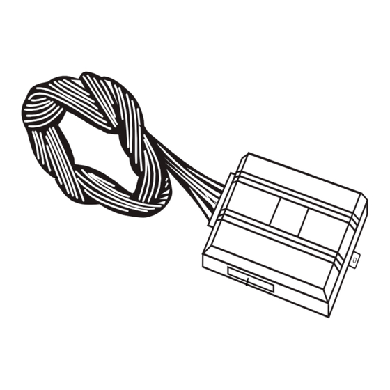
what is included I The control module (see diagram) I Two remote transmitters P/N 491T I A on-board Stinger ® Doubleguard ® shock sensor I A Revenger ® Soft Chirp ® siren I The plug-in status LED I The plug-in Valet ®... -
Page 4: Installation Points To Remember
installation points to remember Do not disconnect the battery if the vehicle has an anti-theft-coded radio. If equipped with an air bag, avoid disconnecting the battery if possible. Many airbag systems will display a diagnostic code through their warning lights after they lose power. Disconnecting the battery requires this code to be erased, which can require a trip to the dealer. -
Page 5: Locations For The Control Module
Some good siren locations: locations for the control module Some things to remember about where to mount the control module: I Never put the control module in the engine compartment! I The first step in hot-wiring a vehicle is removing the driver's side under-dash panel to access the starter and ignition wires. -
Page 6: On-Board Stinger Doubleguard Shock Sensor
on-board stinger doubleguard shock sensor How the control module is mounted is the most important factor in determining the performance of the on-board shock sensor. We recommend two methods for mounting the control module: I Using double-sided tape or hook-and-loop fastener to mount to a trim panel or an air duct, or I Wire-tying to a wire harness. -
Page 7: Locations For The Status Led
locations for the status LED Things to remember when positioning the Status LED: I It should be visible from both sides and the rear of the vehicle, if possible. I It needs at least " clearance to the rear. I It is easiest to use a small removable panel, such as a switch blank or a dash bezel. Remove it before drilling your "... -
Page 8: Obtaining Constant 12V
obtaining constant 12V We recommend two possible sources for 12V constant: the (+) terminal of the battery, or the constant supply to the ignition switch. Always install a fuse within 12 inches of this connection. If the fuse also will be powering other circuits, such as door locks, a power window module, a Nite-Lite ®... -
Page 9: Finding A (+) Parking Light Wire
finding a (+) parking light wire Most vehicles use a (+) parking light circuit. In these vehicles, an optional 8617 relay is required to interface with the light flash feature. The (+) parking light wire is often found near the switch. Many cars have the switch built into the turn signal lever, and in these cars the parking light wire can be found in the steering column. -
Page 10: Finding The Door Pin Switch Circuit
finding the door pin switch circuit The best places to find the door pin switch wire are: I At the pin switch: When testing at the pin switch, check the wire to ensure that it “sees” all the doors. Often, the passenger switch will cover all the doors even if the driver’s switch will not. -
Page 11: Making Your Wiring Connections
5. Cut the wire you suspect of being the starter wire. 6. Attempt to start the car. If the starter engages, reconnect it and go back to Step 3. If the starter does not turn over, you have located the correct wire. making your wiring connections Before making your connections, plan how your wires will be routed through the vehicle. -
Page 12: Primary Harness (H1), 12-Pin Connector
primary harness (H1), 12-pin connector ______ ORANGE (-) 500 mA ARMED OUTPUT H1/1 ______ WHITE (-) 200 mA LIGHT FLASH OUTPUT H1/2 ______ WHITE/BLUE (-) 2V LED OUTPUT H1/3 ______ H1/4 BLACK/WHITE (-) VALET/PROGRAM BUTTON INPUT ______ H1/5 GREEN (-) DOOR TRIGGER INPUT, ZONE 3 ______ H1/6 BLUE... -
Page 13: Primary Harness Wire Connection Guide
primary harness wire connection guide H1/1 ORANGE (-) ground-when-armed output This wire supplies a (-)500 mA ground as long as the system is armed. This output ceases as soon as the system is disarmed. This wire can be used to control the optional Directed 8618 starter kill relay. The 8617 relay assem- bly may also be used as shown in the diagram below. -
Page 14: H1/3
H1/3 WHITE/BLUE (-) 2V LED output Connect this wire to the blue wire on the status LED. Then connect the red wire of the status LED to (+) 12V constant fused. H1/4 BLACK/WHITE valet/program switch input Connect to the gray wire on the Valet/program switch. The black wire on the Valet/program switch should be connected to chassis ground. -
Page 15: H1/7
H1/7 VIOLET (see H1/5 GREEN) H1/8 BLACK (-) chassis ground connection Connect this wire to a clean, paint-free sheet metal location (driver kick panel) using a factory bolt that DOES NOT have any vehicle component grounds attached to it. A screw should only be used when in conjunction with a two-sided lock washer. -
Page 16: H1/10
H1/10 BROWN (+) siren output Connect this to the red wire of the Revenger™ siren. Connect the black wire of the siren to (-) chassis ground, preferably at the same point you grounded the control module’s H1/8 BLACK wire. H1/11 RED (+)12V constant power input Before connecting this wire, remove the supplied fuse. -
Page 17: On-Board Stinger Doubleguard Shock Sensor
on-board stinger doubleguard shock sensor There is a dual-stage shock sensor inside the control unit. Adjustments are made via the rotary control as indi- cated in the diagram. Since the shock sensor does not work well when mounted firmly to metal, we do not recommend screwing down the control module. -
Page 18: Harness 2, (-) Door Lock Outputs
harness 2, (-) door lock outputs ______ H2/A GREEN (-) LOCK ______ H2/B EMPTY UNLESS USING 451M ______ H2/C BLUE (-) UNLOCK These wires provide (-)200mA pulses that are used to control electric door locks. Most common interfaces are described in this section. IMPORTANT! If you mistake a Type C direct-wired system for a Type A positive-pulse system, the module will be damaged! type A: (+) 12V pulses from the switch to the factory relays... - Page 19 type B: (-) pulses from the switch to the factory relays This door lock system is common in many Toyotas, Nissans, Hondas, and Saturns, as well as Fords with the keyless entry system (some other Fords also use Type B). The switch will have three wires on it, and one wire will test ground all the time.
- Page 20 type C: reversing polarity Interfacing with a reversing polarity system requires either two relays or one Directed 451M (not included). It is critical to identify the proper wires and locate the master switch to interface properly. Locate wires that show voltage on lock and unlock.
- Page 21 type D: after-market actuators In order for this system to control one or more after-market actuators, a Directed 451M or two relays (optional) are needed. Vehicles without factory power door locks require the installation of one actuator per door. This requires mounting the door lock actuator inside the door.
-
Page 22: Type E Door Locks
type E: mercedes-benz and audi (1985 & newer) Type E door locks are controlled by an electrically activated vacuum pump. Some Mercedes and Audis use a Type D system. Test by locking doors from the passenger key cylinder. If all the doors lock, the vehicle's door lock system can be controlled with just two relays (optional). - Page 23 type F: one-wire system This type of door lock system usually requires a negative pulse to unlock, and cutting the wire to lock the door. In some vehicles, these are reversed. Type F door lock systems are found in late-model Nissan Sentras, some Nissan 240SX, and Nissan 300ZX 1992-up.
- Page 24 type G: positive multiplex This system is most commonly found in Ford, Mazda, Chrysler and GM vehicles. The door lock switch or door key cylinder may contain either one or two resistors. When interfacing with this type of door lock system, two relays or a DEI 451M must be used.
- Page 25 type H: negative multiplex The system is most commonly found in Ford, Mazda, Chrysler and GM vehicles. The door lock switch or door key cylinder may contain either one or two resistors. When interfacing with this type of door lock system, two relays or a DEI 451M must be used.
-
Page 26: Transmitter/Receiver Learn Routine
transmitter/receiver learn routine ™ The system comes with two transmitters that have been taught to the receiver. The receiver can store up to four different transmitter codes in memory. Use the following learn routine to add transmitters to the system or to change button assignments if desired. -
Page 27: Two-Vehicle Operation With Single Transmitter
Learn Routine™ will be exited if: I Ignition is turned off. I Door is closed. I Valet ® /Program button is pressed too many times. I More than 15 seconds elapses between steps. One long chirp indicates that Learn Routine™ has been exited. two-vehicle operation with single transmitter Two-vehicle operation is possible with the transmitters that come with the system;... -
Page 28: Operating Settings Learn Routine
operating settings learn routine ™ Many of the operating settings of this unit are programmable. They can be changed whenever necessary through a computer-based System Features Learn Routine ™ . The Valet ® /Program push-button switch is used together with a programmed transmitter to change the settings. -
Page 29: Feature Menu
Valet/Program switch. If this is not the desired setting, continue to hold the Valet/Program switch and press the arm/disarm button on the transmitter again. The siren will chirp once indicating that active arming has been programmed. Once the desired setting has been selected, release the Valet/Program switch. You can advance from feature to feature by pressing and releasing the Valet/Program switch the number of times necessary to advance from the feature you just programmed to the feature you wish to access. -
Page 30: Feature Descriptions
feature descriptions The programmable features of this system are described below. 1 ACTIVE/PASSIVE ARMING: When active arming is selected, the system will only arm when the transmitter is used. When set to passive, the system will arm automatically 30 seconds after the last door is closed. Passive arming is indicated by the rapid flashing of the LED when the last protected entry point is closed. -
Page 31: Nuisance Prevention Circuitry (Npc™)
9 DOUBLE PULSE UNLOCK OFF/ON: Some vehicles require two pulses on a single wire to unlock the doors. When the double pulse unlock feature is turned on, the BLUE H2/C wire will supply two negative pulses instead of a single pulse. At the same time, the GREEN H2/A wire will supply two (+) pulses instead of a single pulse. This makes is possible to directly interface with double pulse vehicles without any extra parts. -
Page 32: Valet Mode
valet mode to enter or exit valet mode with the valet/program switch Turn the ignition key on and then off. At any time during the next 10 seconds, press and release the Valet ® switch. Now the Status LED will light constantly if you have entered Valet ®... -
Page 33: Troubleshooting
troubleshooting I Optional starter kill does not work: Is the correct starter wire being interrupted? If the vehicle starts when the starter kill relay is completely dis- connected, the wrong starter wire has been cut and interrupted. I Shock sensor doesn't trigger the alarm: Has the NPC system been triggered? If so, you will hear 5 chirps when disarming.
Need help?
Do you have a question about the 725T and is the answer not in the manual?
Questions and answers