Advertisement
Quick Links
Download this manual
See also:
Owner's Manual
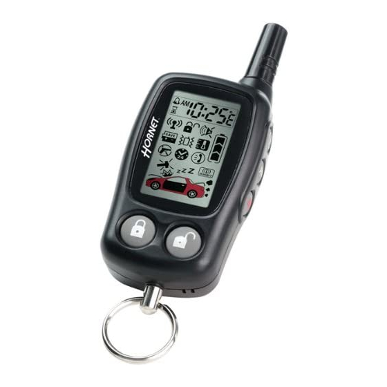
M M o o d d e e l l 7 7 4 4 5 5 T T
I I n n s s t t a a l l l l a a t t i i o o n n G G u u i i d d e e
© 2005 Directed Electronics, Vista, CA N745T 09-05
Advertisement

Subscribe to Our Youtube Channel
Related Manuals for Hornet 745T


Summary of Contents for Hornet 745T
- Page 1 M M o o d d e e l l 7 7 4 4 5 5 T T I I n n s s t t a a l l l l a a t t i i o o n n G G u u i i d d e e ©...
- Page 2 ......................3 3 4 4 Hornet ®...
- Page 3 w w h h a a t t i i s s i i n n c c l l u u d d e e d d ■ Control module ■ One 4-button remote transmitter ■ Plug-in LED system status indicator ■...
- Page 4 I I M M P P O O R R T T A A N N T T ! ! Never use this wire to drive anything but a relay or a low-current input! The tran- sistorized output can only supply 200 mA of current. Connecting directly to a solenoid, motor, or other high-current device will cause it to fail.
- Page 5 H1/4 YELLOW PRIMARY HARNESS TO IGNITION SYSTEM H H 1 1 / / 5 5 B B L L A A C C K K ( ( - - ) ) c c h h a a s s s s i i s s g g r r o o u u n n d d c c o o n n n n e e c c t t i i o o n n Remove any paint and connect this wire to bare metal, preferably with a factory bolt rather than a screw.
- Page 6 H H 1 1 / / 8 8 G G R R E E E E N N ( ( - - ) ) d d o o o o r r t t r r i i g g g g e e r r i i n n p p u u t t , , z z o o n n e e 3 3 Most vehicles use negative door trigger circuits.
- Page 7 H H 1 1 / / 1 1 1 1 W W H H I I T T E E ( ( + + / / - - ) ) s s e e l l e e c c t t a a b b l l e e l l i i g g h h t t f f l l a a s s h h o o u u t t p p u u t t As shipped, this wire should be connected to the (+) parking light wire.
- Page 8 d d o o o o r r l l o o c c k k h h a a r r n n e e s s s s ( ( H H 2 2 ) ) w w i i r r e e c c o o n n n n e e c c t t i i o o n n g g u u i i d d e e ______ V V I I O O L L E E T T * * L L O O C C K K R R E E L L A A Y Y , , N N O O R R M M A A L L L L Y Y O O P P E E N N...
- Page 9 There are eight common types of door lock circuits (some vehicles use more unusual systems): ■ T T y y p p e e A A : : Three-wire (+) pulse controlling factory lock relays. Most GM, some Ford and Chrysler, 1995 Saturn, some new VW, newer BMW.
- Page 10 t t y y p p e e A A : : p p o o s s i i t t i i v v e e - - t t r r i i g g g g e e r r e e d d , , r r e e l l a a y y - - d d r r i i v v e e n n s s y y s s t t e e m m The system can control Type A door locks directly, with no additional parts.
- Page 11 t t y y p p e e B B : : n n e e g g a a t t i i v v e e - - t t r r i i g g g g e e r r e e d d , , r r e e l l a a y y - - d d r r i i v v e e n n s s y y s s t t e e m m This system is common in many Toyota, Nissan, Honda, and Saturn models, as well as Fords with the keyless- entry system (some other Fords also use Type B).
- Page 12 t t y y p p e e C C : : r r e e v v e e r r s s i i n n g g p p o o l l a a r r i i t t y y s s y y s s t t e e m m VIOLET UNLOCK #87 NORMALLY OPEN (INPUT) H2/A...
- Page 13 t t y y p p e e D D : : a a d d d d i i n n g g o o n n e e o o r r m m o o r r e e a a f f t t e e r r - - m m a a r r k k e e t t a a c c t t u u a a t t o o r r s s Vehicles without factory power door locks require the installation of one actuator per door.
- Page 14 t t y y p p e e E E : : e e l l e e c c t t r r i i c c a a l l l l y y - - a a c c t t i i v v a a t t e e d d v v a a c c u u u u m m This system is found in Mercedes-Benz and Audi 1985 and newer.
- Page 15 t t y y p p e e F F : : o o n n e e - - w w i i r r e e s s y y s s t t e e m m ( ( c c u u t t t t o o l l o o c c k k , , g g r r o o u u n n d d t t o o u u n n l l o o c c k k ) ) This type of door lock system usually requires a negative pulse to unlock, and cutting the wire to lock the door.
- Page 16 t t y y p p e e G G : : p p o o s s i i t t i i v v e e ( ( + + ) ) m m u u l l t t i i p p l l e e x x This system is most commonly found in Ford, Mazda, Chrysler and GM vehicles.
- Page 17 VIOLET UNLOCK #87 NORMALLY OPEN (INPUT) H 2 / G VIOLET & VIOLET/BLACK ARE COMMON AT FUSE HOLDER UNLOCK RESISTOR ON-BOARD (IF REQUIRED) #87A UNLOCK RELAY H 2 / F BLUE/BLACK UNLOCK #30 COMMON (OUTPUT) VEHICLE FUSED +12 VOLT CONSTANT H 2 / E BROWN/BLACK NOT USED...
- Page 18 t t y y p p e e H H : : n n e e g g a a t t i i v v e e ( ( - - ) ) m m u u l l t t i i p p l l e e x x The system is most commonly found in Ford, Mazda, Chrysler and GM vehicles.
- Page 19 a a u u x x i i l l i i a a r r y y h h a a r r n n e e s s s s ( ( H H 3 3 ) ) w w i i r r e e c c o o n n n n e e c c t t i i o o n n g g u u i i d d e e ______ V V I I O O L L E E T T / / B B L L A A C C K K ( ( - - ) ) 2 2 0 0 0 0 m m A A C C H H A A N N N N E E L L 4 4 O O U U T T P P U U T T...
- Page 20 H H 3 3 / / 3 3 B B L L U U E E ( ( - - ) ) 2 2 0 0 0 0 m m A A s s e e c c o o n n d d u u n n l l o o c c k k o o u u t t p p u u t t This output is used for progressive door unlock.
- Page 21 D D r r i i v v e e r r ’ ’ s s D D o o o o r r U U n n l l o o c c k k O O n n l l y y ( ( T T y y p p e e B B ) ) : : H3/3 BLUE (-) 200...
- Page 22 STARTER WIRE IN VEHICLE STARTER MOTOR/ STARTER MOTOR RELAY DIA-250 DIRECTED SECURITY SYSTEM p p l l u u g g - - i i n n L L E E D D a a n n d d v v a a l l e e t t / / p p r r o o g g r r a a m m s s w w i i t t c c h h The LED and the Valet/Program switch both plug into the control module.
-
Page 23: Inside The Case
i i n n t t e e r r n n a a l l p p r r o o g g r r a a m m m m i i n n g g j j u u m m p p e e r r NOTE: JUMPER IS INSIDE THE CASE l l i i g g h h t t f f l l a a s s h h j j u u m m p p e e r r... -
Page 24: Control Unit
o o n n - - b b o o a a r r d d d d u u a a l l s s t t a a g g e e i i m m p p a a c c t t s s e e n n s s o o r r Less Sensitive More Sensitive There is a dual-stage impact sensor inside the control unit. - Page 25 t t r r a a n n s s m m i i t t t t e e r r / / r r e e c c e e i i v v e e r r l l e e a a r r n n r r o o u u t t i i n n e e The system comes with two transmitters that have been taught to the receiver.
- Page 26 T T r r a a n n s s m m i i t t . . While H H O O L L D D I I N N G G the Valet/Program switch, press the transmitter button that you wish to assign to that channel.
-
Page 27: Beep/Vibrate Notification
L L C C D D 2 2 - - w w a a y y t t r r a a n n s s m m i i t t t t e e r r a a d d d d i i t t i i o o n n a a l l c c o o n n t t r r o o l l s s The LCD 2-way transmitter has the following additional controls: operates No function... - Page 28 s s y y s s t t e e m m f f e e a a t t u u r r e e s s l l e e a a r r n n r r o o u u t t i i n n e e Many of the features of this unit are programmable.
- Page 29 T T o o e e x x i i t t t t h h e e C C o o d d e e L L e e a a r r n n i i n n g g , , d d o o o o n n e e o o f f t t h h e e f f o o l l l l o o w w i i n n g g : : ■...
- Page 30 3 3 I I G G N N I I T T I I O O N N - - C C O O N N T T R R O O L L L L E E D D D D O O O O R R L L O O C C K K / / U U N N L L O O C C K K O O N N / / O O F F F F : : When turned on, the doors will lock three seconds after the ignition is turned on and unlock when the ignition is turned off.
- Page 31 1 1 0 0 C C o o m m f f o o r r t t c c l l o o s s u u r r e e f f e e a a t t u u r r e e : : This feature is designed to integrate with vehicles that can close the power windows and sunroof by holding the key in the driver door lock position, and will operate on both single input systems and two pulses input dead bolt systems.
- Page 32 t t a a b b l l e e o o f f z z o o n n e e s s When using the Diagnostic functions, use the Table of Zones to see which input has triggered the system. It is also helpful in deciding which input to use when connecting optional sensors and switches.
- Page 33 ■ D D o o o o r r i i n n p p u u t t d d o o e e s s n n o o t t r r e e s s p p o o n n d d w w i i t t h h t t h h e e p p r r o o g g r r e e s s s s i i v v e e t t r r i i g g g g e e r r , , b b u u t t w w i i t t h h i i m m m m e e d d i i a a t t e e f f u u l l l l a a l l a a r r m m : : Does the LED indicate that the trigger was caused by the impact sensor? (See Table of Zones section of this guide.) The impact sensor, if set to extreme sensitivity, may be detecting the door unlatching before the door switch sends its signal.
- Page 34 w w i i r r i i n n g g q q u u i i c c k k r r e e f f e e r r e e n n c c e e d d i i a a g g r r a a m m 12-Pin H1 Primary Harness H4 Starter Interrupt...
Need help?
Do you have a question about the 745T and is the answer not in the manual?
Questions and answers