
Subscribe to Our Youtube Channel
Related Manuals for Hornet 720T


Summary of Contents for Hornet 720T
-
Page 1: Installation Guide
® Model 720T Installation Guide ® © 2001 Directed Electronics, Inc. Vista, CA N720T 3-01 Rev. D 1.1... -
Page 2: Table Of Contents
table of contents What Is Included ..............3 Installation Points to Remember. -
Page 3: What Is Included
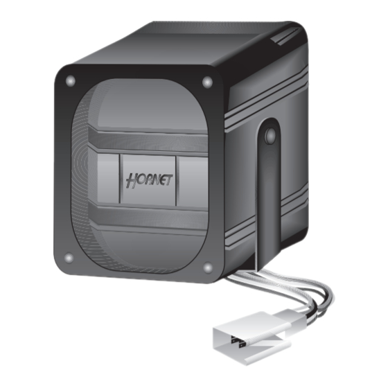
what is included I The control module (see diagram) I The siren and voice command module, on-board the control module I A Stinger Doubleguard dual-stage shock/impact sensor, on-board the control module I Two 2-button remote transmitters I H1 6-Pin Primary Harness I The status LED I A mounting bracket I A hardware pack... -
Page 4: Installation Points To Remember
installation points to remember before beginning the installation I Do not disconnect the battery if the vehicle has an anti-theft-coded radio. I If equipped with an air bag, avoid disconnecting the battery if possible. Many airbag systems will display a diagnostic code through their warning lights after they lose power. -
Page 5: Primary Harness (H1) Wire Connection Guide
primary harness (H1) wire connection guide H1/1 ORANGE (-) GROUND-WHEN-ARMED OUTPUT This wire supplies a (-) 500 mA ground as long as the system is armed. This output ceases as soon as the system is disarmed. This output can be used to interrupt the starter circuit using an optional 8618 starter kill relay. H1/2 WHITE (-) LIGHT FLASH OUTPUT The unit supplies a 200 mA output that can be used to flash the parking lights of the vehicle. -
Page 6: Transmitter/Receiver Learn Routine
H1/6 RED (+)12V CONSTANT POWER INPUT Before connecting this wire, remove the supplied fuse. Connect to the battery positive terminal or to the (+) 12V feed for the dome light circuit. NOTE: Always use a fuse within 12 inches of the point you obtain (+) 12V. Do not use the 10A fuse in the harness for this purpose. -
Page 7: Operating Settings Learn Routine
operation settings learn routine Many of the system features are programmable. The operation settings learn routine is used to access and program the system features. You must have a programmed transmitter to program features. To enter Learn Routine: Arm the system. Disarm the system. -
Page 8: Feature Descriptions
After programming a feature, another feature can be selected by repeating steps 3 and 4. The Learn Routine will be exited if you wait longer than five seconds between steps. The system will exit Learn Routine immediately if you repeat steps 3 and 4 more times than there are features. When the operation settings learn routine is exited, the unit will chirp once followed by a long chirp. - Page 9 Within five seconds, press and hold Button II on the transmitter until the unit generates a long chirp. Release Button II on the transmitter. To test and adjust the current Warn Away setting: Strike the vehicle to test the current setting. If the impact is detected, the unit will chirp three or four times. If the current setting is acceptable, do nothing and the unit will exit shock sensor adjustment mode.
-
Page 10: Troubleshooting
troubleshooting I The current sensor does not work. Is it programmed off? Is it programmed for five minute delay? (Refer to the Operation Settings Learn Routine section of this guide.) The current sensor can sense the domelight circuit more effectively if the red (+) 12V input wire is connected directly to the domelight positive circuit.
Need help?
Do you have a question about the 720T and is the answer not in the manual?
Questions and answers