Bosch FAP-DO420 Operation Manual
Automatic fire detectors lsn improved
Hide thumbs
Also See for FAP-DO420:
- Operation manual (46 pages) ,
- Installation and operation manual (25 pages)

Related Manuals for Bosch FAP-DO420


Summary of Contents for Bosch FAP-DO420
- Page 1 Automatic Fire Detectors LSN improved FAP-DO420/FAP-420/FAH-420 Operation Guide...
-
Page 3: Table Of Contents
Installation Note for FAA-420-RI Remote Indicator 6.7.2 MPA External Detector Alarm Display Service and Detector Test Accessories Order Information Detector Variants Detector Bases Detector Accessories Installation Accessories Detector Base Sounders Service accessories Bosch Sicherheitssysteme GmbH Operation Guide 12/2012 | 8.1 | F.01U.003.448... -
Page 4: En | Table Of Contents
Test Instructions for All Fire Detectors With Optical Sensor 8.3.2 Test Instructions for FAP‑DOTC420 / FAP‑DOT420 / FAP‑OTC 420 / FAP‑OT 420 Warranty Repair Disposal Additional documentation Technical Data Appendices 10.1 Abbreviations 12/2012 | 8.1 | F.01U.003.448 Operation Guide Bosch Sicherheitssysteme GmbH... -
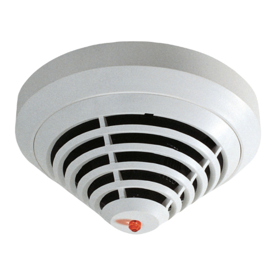
Page 5: Product Description
– FAP-DOT420: combined dual-optical and thermal smoke detector – FAP-OT 420: combined optical and thermal smoke detector – FAP-DO420: dual-optical smoke detector – FAP-O 420/FAP-O 420 KKW: optical smoke detector – FAH-T 420/FAH-T 420 KKW: thermal detector The line technology variants are: –... -
Page 6: System Overview
(Dual Ray technology). This allows fires to be detected early and even the smallest quantities of smoke (TF1, TF9) to be reliably detected. Notice! The FAP-DO420 smoke detector makes an alarm decision based on an intelligent combination of the following criteria: Amount of smoke density measured... -
Page 7: Chemical Sensor (Gas Sensor)
Individual detector identification on the fire panel in the event of an alarm. Alarm indication on the detector with a flashing red LED. – Programmable, i.e. can be adjusted to the area of operation. Bosch Sicherheitssysteme GmbH Operation Guide 12/2012 | 8.1 | F.01U.003.448... - Page 8 The device is supported by the WinPara programming software version 4.85 or higher. For DO detectors, note: Notice! The device cannot be used with the FPA-5000 type A panel controller. 12/2012 | 8.1 | F.01U.003.448 Operation Guide Bosch Sicherheitssysteme GmbH...
-
Page 9: Planning
15 V DC. Use in Areas with Elevated Radioactivity There are two detector types available especially for use in areas with elevated radioactivity, such as in nuclear power plants: – FAP-O 420-KKW Bosch Sicherheitssysteme GmbH Operation Guide 12/2012 | 8.1 | F.01U.003.448... - Page 10 Automatic Fire Detectors LSN en | Planning improved – FAH-T 420-KKW 12/2012 | 8.1 | F.01U.003.448 Operation Guide Bosch Sicherheitssysteme GmbH...
-
Page 11: Programming
O, T High (A2) High High diff Office (smoker)/waiting room/ O, T High (A2) Low* diff restaurant/meeting room = default setting Office (day mode) O, T Low (B) Medium High diff Bosch Sicherheitssysteme GmbH Operation Guide 12/2012 | 8.1 | F.01U.003.448... -
Page 12: Fap-Dot420 / Fap-Ot 420
The default setting of the FAP-DOT 420 and FAP-OT 420 detector types in RPS and WinPara is "Office (day mode)". For a description of this setting, see the below table. 12/2012 | 8.1 | F.01U.003.448 Operation Guide Bosch Sicherheitssysteme GmbH... -
Page 13: Fap-Do420 / Fap-O 420 / Fap-O 420-Kkw
The default setting of the FAP-DO 420 and FAP-O 420 detector types in RPS and WinPara is "Medium". For a list of possible installation locations and corresponding sensitivity settings, see the below table. Bosch Sicherheitssysteme GmbH Operation Guide 12/2012 | 8.1 | F.01U.003.448... -
Page 14: Fah-T 420/Fah-T 420-Kkw
The thermal differential unit enables class A1R/A2R detectors to respond at T<54 °C and class BR detectors at T<69 °C. The selection of the sensitivity class also depends on the installation height of the detector. 12/2012 | 8.1 | F.01U.003.448 Operation Guide Bosch Sicherheitssysteme GmbH... - Page 15 2 min 5 min 30 s 30 s 2 min 20 s 1 min 3 min 13 s 20 s 1 min 40 s 40 s 2 min 25 s Bosch Sicherheitssysteme GmbH Operation Guide 12/2012 | 8.1 | F.01U.003.448...
-
Page 16: Connection
Der MS 400 is the standard detector base. It has seven screw terminals. MS 400 B MS 400 standard detector base with Bosch-branding. FAA-420-SEAL For using the FAP/FAH detectors in damp environments you can supplement the MS 400 and MS 400 B detector bases with the FAA-420-SEAL damp room seal. -
Page 17: Installing The Base
Cables can be fed in and out on the same side. On the MSF 400 and MSC 420, punch out the integrated seal with a sharp tool. Do not cut with a knife. Bosch Sicherheitssysteme GmbH Operation Guide 12/2012 | 8.1 | F.01U.003.448... -
Page 18: Connection
Automatic Fire Detectors LSN en | Connection improved Ø 120 Ø 100 Connection Notice! Keep shield wire as short as possible and insulate. 12/2012 | 8.1 | F.01U.003.448 Operation Guide Bosch Sicherheitssysteme GmbH... -
Page 19: Connecting The Ms 400/Ms 400 B
Connection | en improved 5.3.1 Connecting the MS 400/MS 400 B LSN +/L..b max. 30 V DC a1/a2 (LSN -/L..a) max. 3 m – MPA/ FAA-420-RI Yellow, connection to b1/b2 (LSN +) Bosch Sicherheitssysteme GmbH Operation Guide 12/2012 | 8.1 | F.01U.003.448... -
Page 20: Connecting The Faa-Msr 420
Connecting the FAA‑MSR 420 Maximum contact load (resistive load) of the change-over contact relay: – 62.5 VA: 0.5 A at 125 V AC – 30 W: 1 A at 30 V DC 12/2012 | 8.1 | F.01U.003.448 Operation Guide Bosch Sicherheitssysteme GmbH... - Page 21 3 m – MPA / FAA-420-RI Yellow, connection to b1/b2 (LSN +) White, connection to a1/a2 (LSN -) MPA/FAA‑420‑RI: Red, connection to b1 MPA/FAA‑420‑RI: Black, connection to c (indicator output) Bosch Sicherheitssysteme GmbH Operation Guide 12/2012 | 8.1 | F.01U.003.448...
-
Page 22: Detector Base Sounders
The detector module can be locked in the base (removal protection). The locking feature is activated by breaking the bolt (X) out of the base and pushing it into the corresponding guide, as shown in , page 22. 12/2012 | 8.1 | F.01U.003.448 Operation Guide Bosch Sicherheitssysteme GmbH... -
Page 23: Detector Removal
There are three rotary switches on the bottom of the detector; these are used to select automatic or manual address allocation with or without auto-detection. The following settings are possible: Bosch Sicherheitssysteme GmbH Operation Guide 12/2012 | 8.1 | F.01U.003.448... - Page 24 If an LSN classic element is present, only 127 elements can be used in the loop. Please note that only loop or stub structures can be used for configurations with mixed LSN classic and LSN improved elements. 12/2012 | 8.1 | F.01U.003.448 Operation Guide Bosch Sicherheitssysteme GmbH...
-
Page 25: Accessories
If the detector is mounted in a sports facility, for example, the protective basket prevents balls or other sports equipment from hitting the detector and damaging it. Bosch Sicherheitssysteme GmbH Operation Guide 12/2012 | 8.1 | F.01U.003.448... -
Page 26: Ssk 400 Protective Dust Cover
Installation Note for FAA-420-RI Remote Indicator Notice! The FAA-420-RI Remote Indicator must be installed such that the broad side of the red alarm indication (see image, item B) follows the observer's line of sight. 12/2012 | 8.1 | F.01U.003.448 Operation Guide Bosch Sicherheitssysteme GmbH... - Page 27 In order to prevent damage to the device, ensure that the maximum current consumption of 20 mA is not exceeded. Point-type automatic Bosch detectors already have an internal resistor that limits current con- sumption. Installation Before assembly, remove the cap from the base plate: To unlock the snap-fit hooks (see image, item C) with a flat object (e.g.
-
Page 28: Mpa External Detector Alarm Display
The flat side of the prism (see Installation note, page 28, item Y) must follow the observer's line of sight. 1 2 3 4 Figure 6.1: Installation of the MPA External Detector Alarm Display Connection The MPA is connected via four Wago terminals. 12/2012 | 8.1 | F.01U.003.448 Operation Guide Bosch Sicherheitssysteme GmbH... - Page 29 1 2 3 4 A resistor is necessary to connect to terminal 4; otherwise, the LED may be damaged. All current Bosch detectors are equipped with an internal resistor to restrict current consumption. Caution! If the current consumption for the connected detector exceeds 20 mA, it can lead to the mal- function of or damage to the MPA.
-
Page 30: Service And Detector Test Accessories
Note: Only use the plastic bowl in conjunction with the adapter pole. On the adapter pole there is a rubber bearing that cushions the turning motion when removing the fire detectors and prevents damage. 12/2012 | 8.1 | F.01U.003.448 Operation Guide Bosch Sicherheitssysteme GmbH... - Page 31 DU = 12 pieces Solo CO testing gas Spray can with CO testing gas for multisensor detectors with C sensor. Contents: approx. 4 l compressed gas DU = 12 pieces Bosch Sicherheitssysteme GmbH Operation Guide 12/2012 | 8.1 | F.01U.003.448...
- Page 32 FME-TS3 Smoke Capsule Smoke Capsule for FME-TESTIFIRE testing tool FME-TC3 CO Capsule CO Capsule for FME-TESTIFIRE testing tool 12/2012 | 8.1 | F.01U.003.448 Operation Guide Bosch Sicherheitssysteme GmbH...
- Page 33 SOLO610 Test Equipment Bag The SOLO610 Test Equipment Bag is made from strongly woven polyester with a PVC coating and is suitable for carrying or storing test and service products. Bosch Sicherheitssysteme GmbH Operation Guide 12/2012 | 8.1 | F.01U.003.448...
-
Page 34: Order Information
Standard detector base, for surface-mount and flush- 4.998.021.535 mount cable insertion MS 400 B Standard detector base, for surface-mount and flush- F.01U.215.139 mount cable insertion, Bosch-branded FAA-420-SEAL Damp room seal for MS 400 and MS 400 B detector F.01U.215.142 bases FAA-MSR 420 Detector Base with Relay F.01U.508.658... -
Page 35: Installation Accessories
Plastic caps for the SOLO200 Detector Removal Tool 4.998.082.502 (scope of delivery = 2 pieces) FME-420-ADAP Tool Adapter for MS 420 F.01U.510.318 SOLO330 Smoke Detector Tester 4.998.112.071 Solo A3-001 Test Aerosol for Optical Smoke Detectors 4.998.112.074 Bosch Sicherheitssysteme GmbH Operation Guide 12/2012 | 8.1 | F.01U.003.448... - Page 36 Battery for SOLO461 Heat Detector Tester 4.998.147.576 FME-TESTIFIRE Multi-Stimulus Testing Tool F.01U.143.407 FME-TS3 Smoke Capsule F.01U.143.404 FME-TC3 CO-Capsule F.01U.143.405 SOLO100 Telescopic Access Pole 4.998.112.069 SOLO101 Fixed Extension Pole 4.998.112.070 SOLO610 Test Equipment Bag 4.998.112.073 12/2012 | 8.1 | F.01U.003.448 Operation Guide Bosch Sicherheitssysteme GmbH...
-
Page 37: Maintenance And Service
– Maintenance and inspection work should be carried out regularly and by trained personnel. – BOSCH ST recommends carrying out a functional and visual inspection at least once a year. Testing Detector Type FAP‑DO420 FAP-O FAH-T 420 FAP‑DOT420... -
Page 38: Notes For The Service
3931859 was manufactured in 2003. Current analog values Optical system value (display of the current contamination value): 0 . . . 170 Initial set-up value for a new detector 12/2012 | 8.1 | F.01U.003.448 Operation Guide Bosch Sicherheitssysteme GmbH... - Page 39 The optical initial set-up value of a new detector is stored in the integrated EEPROM during the final inspection. The contamination value specifies by how much this analog value has increased in comparison with the delivery state. Bosch Sicherheitssysteme GmbH Operation Guide 12/2012 | 8.1 | F.01U.003.448...
-
Page 40: Detector Type Encoding
10 seconds. Testing outside the Revision Mode If you want to test detectors in controls, 2-detector or 2-goup dependencies, you must test them outside the revision mode. Proceed as follows: 12/2012 | 8.1 | F.01U.003.448 Operation Guide Bosch Sicherheitssysteme GmbH... -
Page 41: Test Instructions For Fap-Dotc420 / Fap-Dot420 / Fap-Otc 420 / Fap-Ot 420
FME-TESTIFIRE) Warranty Defective detectors are exchanged free of charge in the case of a claim under the warranty. Repair In the event of a defect, the entire detector is exchanged. Bosch Sicherheitssysteme GmbH Operation Guide 12/2012 | 8.1 | F.01U.003.448... -
Page 42: Disposal
Notice! For those with access rights, the current product information and the installation guide en- closed with the device are available in PDF format from the Bosch Security Systems Extranet at http://www.boschsecurity.com. 12/2012 | 8.1 | F.01U.003.448 Operation Guide Bosch Sicherheitssysteme GmbH... -
Page 43: Technical Data
-20 °C. . . +50 °C -20 °C. . . +65 °C temperature Permitted relative humidity < 95% (non-condensing) Protection category IP 40/IP 43 with detector base with damp room seal according to EN 60529 Bosch Sicherheitssysteme GmbH Operation Guide 12/2012 | 8.1 | F.01U.003.448... - Page 44 > 54 °C/> 69 °C > 54 °C/> 69 °C – Chemical sensor: ppm range Max. monitoring area 120 m (observe VdS guidelines) Max. installation height 16 m (observe VdS guidelines) 12/2012 | 8.1 | F.01U.003.448 Operation Guide Bosch Sicherheitssysteme GmbH...
- Page 45 Max. monitoring area 120 m (observe VdS 40 m (observe VdS guidelines) guidelines) Max. installation height 16 m (observe VdS 7.5 m (observe VdS guidelines) guidelines) Permitted air speed 20 m/s Bosch Sicherheitssysteme GmbH Operation Guide 12/2012 | 8.1 | F.01U.003.448...
- Page 46 Housing material/color ABS/white, similar to RAL 9010, matte surface Weight without packaging Approx. 75 g Weight with packaging Approx. 115 g Product ID F.01U.508.813 / F.01U. F.01U.508.915 / F.01U. 508.687 508.686 12/2012 | 8.1 | F.01U.003.448 Operation Guide Bosch Sicherheitssysteme GmbH...
-
Page 47: Appendices
Local Security Network Product Information Polypropylene Universelle Europazentrale (Universal European Central) Universelle Gefahrenmeldezentrale (Universal danger detection system) Association of German Electrical Engineers VdS Schadenverhütung GmbH Optical/thermal/chemical (gas) Optical/thermal Optical Thermal Bosch Sicherheitssysteme GmbH Operation Guide 12/2012 | 8.1 | F.01U.003.448... - Page 50 Bosch Sicherheitssysteme GmbH Robert-Bosch-Ring 5 85630 Grasbrunn Germany www.boschsecurity.com © Bosch Sicherheitssysteme GmbH, 2012...
Need help?
Do you have a question about the FAP-DO420 and is the answer not in the manual?
Questions and answers