Bosch FAP-DO420 Operation Manual
Automatic fire detectors lsn improved version
Hide thumbs
Also See for FAP-DO420:
- Operation manual (50 pages) ,
- Installation and operation manual (25 pages)

Subscribe to Our Youtube Channel
Related Manuals for Bosch FAP-DO420


Summary of Contents for Bosch FAP-DO420
- Page 1 Automatic Fire Detectors LSN improved version FAP-DO420/FAP-420/FAH-420 Operation Guide...
-
Page 3: Table Of Contents
Use in a Local Security Network (LSN/LSN improved version) Use in Areas with Elevated Radioactivity Programming FAP-DOTC420 / FAP-OTC 420 FAP-DOT420 / FAP-OT 420 FAP-DO420 / FAP-O 420 / FAP-O 420-KKW FAH-T 420/FAH-T 420-KKW Connection Overview of Detector Bases Installing the Base Connection 5.3.1... - Page 4 Test Instructions for All Fire Detectors With Optical Sensor 8.3.2 Test Instructions for FAP-DOTC420 / FAP-DOT420 / FAP-OTC 420 / FAP-OT 420 Warranty Repair Disposal Additional documentation Technical Data Appendices Abbreviations Document Change History F.01U.003.448 | 8.0 | 2011.10 Operation Guide Bosch Sicherheitssysteme GmbH...
-
Page 5: Product Description
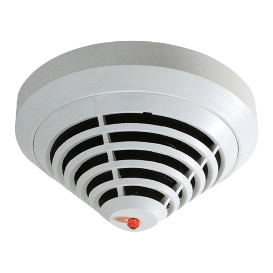
Automatic Fire Detectors LSN improved version series. Wherever the term DO detector is used in this document, this refers to the following detectors: FAP-DO420, FAP-DOT420, FAP-DOTC420. The FAP-420/FAH-420 Automatic Fire Detectors LSN improved version series is specially designed for connection to the FPA-1200 and the FPA-5000 Modular Fire Panel. The fire... -
Page 6: System Overview
(Dual Ray technology). This allows fires to be detected early and even the smallest quantities of smoke (TF1) to be reliably detected. NOTICE! The FAP-DO420 smoke detector makes an alarm decision based on an intelligent combination of the following criteria: –... -
Page 7: Chemical Sensor (Gas Sensor)
Individual detector identification on the fire panel in the event of an alarm. Alarm indication on the detector with a flashing red LED. – Programmable, i.e. can be adjusted to the area of operation. Bosch Sicherheitssysteme GmbH Operation Guide F.01U.003.448 | 8.0 | 2011.10... - Page 8 – Flexible network structures without additional elements ("T-Tapping") are possible. – Automatic or manual detector addressing selectable. – Compliant with EN 54, EN 50131 and VdS guidelines. F.01U.003.448 | 8.0 | 2011.10 Operation Guide Bosch Sicherheitssysteme GmbH...
-
Page 9: Planning
Use in Areas with Elevated Radioactivity There are two detector types available especially for use in areas with elevated radioactivity, such as in nuclear power plants: – FAP-O 420-KKW – FAH-T 420-KKW Bosch Sicherheitssysteme GmbH Operation Guide F.01U.003.448 | 8.0 | 2011.10... -
Page 10: Programming
Switch to thermal maximum (T sensor sensitivity = A2S, O sensor = switched off). In the case of the purely optical FAP-O 420 and FAP-DO420 detectors, the sensitivity of the optical sensor can be set to three levels. Depending on the operating location, the optical sensor in the detector is thus adjusted to the environmental conditions. - Page 11 *** For FAP-DOTC420: does not comply with EN54-7 For details on installation height, see Section 4.4 FAH-T 420/FAH-T 420-KKW, page 13 NOTICE! The FAP-DOTC420 detector is not supported by the WinPara programming software. Bosch Sicherheitssysteme GmbH Operation Guide F.01U.003.448 | 8.0 | 2011.10...
-
Page 12: Fap-Dot420 / Fap-Ot 420
NOTICE! The FAP-DOT420 detector is not supported by the WinPara programming software. FAP-DO420 / FAP-O 420 / FAP-O 420-KKW NOTICE! The default setting of the FAP-DO 420 and FAP-O 420 detector types in RPS and WinPara is "Medium". For a list of possible installation locations and corresponding sensitivity settings, see the below table. -
Page 13: Fah-T 420/Fah-T 420-Kkw
To maintain the greatest possible security against false alarms, classes A1 and A1R should not be selected for room heights below 6 m, although these classes are in theory permitted. Furthermore, the expected application temperature must be taken into consideration. Bosch Sicherheitssysteme GmbH Operation Guide F.01U.003.448 | 8.0 | 2011.10... - Page 14 2 min 5 min 30 s 30 s 2 min 20 s 1 min 3 min 13 s 20 s 1 min 40 s 40 s 2 min 25 s F.01U.003.448 | 8.0 | 2011.10 Operation Guide Bosch Sicherheitssysteme GmbH...
-
Page 15: Connection
Der MS 400 is the standard detector base. It has seven screw terminals. MS 400 B MS 400 standard detector base with Bosch-branding. FAA-420-SEAL For using the FAP/FAH detectors in damp environments you can supplement the MS 400 and MS 400 B detector bases with the FAA-420-SEAL damp room seal. -
Page 16: Installing The Base
Cables can be fed in and out on the same side. On the MSF 400 and MSC 420, punch out the integrated seal with a sharp tool. Do not cut with a knife. F.01U.003.448 | 8.0 | 2011.10 Operation Guide Bosch Sicherheitssysteme GmbH... -
Page 17: Connection
Automatic Fire Detectors LSN improved Connection | en version Ø 120 Ø 100 Connection NOTICE! Keep shield wire as short as possible and insulate. Bosch Sicherheitssysteme GmbH Operation Guide F.01U.003.448 | 8.0 | 2011.10... -
Page 18: Connecting The Ms 400/Ms 400 B
Red, connection to +V Black, connection to 0 V Green, connection to shielding wire Indicator output +V/0 V Terminals for looping through the supply voltage for downstream elements MPA/FAA-420-RI Remote indicator F.01U.003.448 | 8.0 | 2011.10 Operation Guide Bosch Sicherheitssysteme GmbH... -
Page 19: Connecting The Faa-Msr 420
MPA/FAA-420-RI: Black, connection to c (indicator output) Green, connection to shield wire NC/C/NO Change-over contact relay +V/0 V Terminals for looping through the supply voltage for downstream elements MPA/FAA-420-RI remote indicator Bosch Sicherheitssysteme GmbH Operation Guide F.01U.003.448 | 8.0 | 2011.10... -
Page 20: Detector Base Sounders
The detector module can be locked in the base (removal protection). The locking feature is activated by breaking the bolt (X) out of the base and pushing it into the corresponding guide, as shown in Figure 5.1. F.01U.003.448 | 8.0 | 2011.10 Operation Guide Bosch Sicherheitssysteme GmbH... -
Page 21: Detector Removal
There are three rotary switches on the bottom of the detector; these are used to select automatic or manual address allocation with or without auto-detection. The following settings are possible: Bosch Sicherheitssysteme GmbH Operation Guide F.01U.003.448 | 8.0 | 2011.10... - Page 22 If an LSN classic element is present, only 127 elements can be used in the loop. Please note that only loop or stub structures can be used for configurations with mixed LSN classic and LSN improved elements. F.01U.003.448 | 8.0 | 2011.10 Operation Guide Bosch Sicherheitssysteme GmbH...
-
Page 23: Accessories
If the detector is mounted in a sports facility, for example, the protective basket prevents balls or other sports equipment from hitting the detector and damaging it. Bosch Sicherheitssysteme GmbH Operation Guide F.01U.003.448 | 8.0 | 2011.10... -
Page 24: Ssk 400 Protective Dust Cover
Installation Note for FAA-420-RI Remote Indicator NOTICE! The FAA-420-RI Remote Indicator must be installed such that the broad side of the red alarm indication (see image, item B) follows the observer's line of sight. F.01U.003.448 | 8.0 | 2011.10 Operation Guide Bosch Sicherheitssysteme GmbH... - Page 25 In order to prevent damage to the device, ensure that the maximum current consumption of 20 mA is not exceeded. Point-type automatic Bosch detectors already have an internal resistor that limits current consumption. Installation Before assembly, remove the cap from the base plate: To unlock the snap-fit hooks (see image, item C) with a flat object (e.g.
-
Page 26: Mpa External Detector Alarm Display
For flush-mounted cable insertion, feed the cable through the opening beneath the connection board. NOTICE! The flat side of the prism (see Figure 6.1, item Y) must follow the observer's line of sight. F.01U.003.448 | 8.0 | 2011.10 Operation Guide Bosch Sicherheitssysteme GmbH... - Page 27 Entry point static (LED flashes) A resistor is necessary to connect to terminal 4; otherwise, the LED 1 2 3 4 may be damaged. All current Bosch detectors are equipped with an internal resistor to restrict current consumption. Bosch Sicherheitssysteme GmbH Operation Guide...
-
Page 28: Service And Detector Test Accessories
The plastic caps enable the fire detector to be securely gripped and protect the detector surface against damage. RTL-cap plastic caps for the SOLO200 Detector Removal Tool Scope of delivery = 2 pieces F.01U.003.448 | 8.0 | 2011.10 Operation Guide Bosch Sicherheitssysteme GmbH... - Page 29 The SOLO461 uses patented CAT™ technology (Cross Air Technology), which bundles the air and feeds it to the sensor horizontally, regardless of the size or form of the detector. Bosch Sicherheitssysteme GmbH Operation Guide F.01U.003.448 | 8.0 | 2011.10...
- Page 30 SOLO610 Test Equipment Bag The SOLO610 Test Equipment Bag is made from strongly woven polyester with a PVC coating and is suitable for carrying or storing test and service products. F.01U.003.448 | 8.0 | 2011.10 Operation Guide Bosch Sicherheitssysteme GmbH...
-
Page 31: Order Information
Standard detector base, for surface-mount and flush- 4.998.021.535 mount cable insertion MS 400 B Standard detector base, for surface-mount and flush- F.01U.215.139 mount cable insertion, Bosch-branded FAA-420-SEAL Damp room seal for MS 400 and MS 400 B detector F.01U.215.142 bases FAA-MSR 420 Detector Base with Relay F.01U.508.658... -
Page 32: Installation Accessories
SOLO461 Heat Detector Tester 4.998.112.072 SOLO720 Battery for SOLO461 Heat Detector Tester 4.998.147.576 FME-TESTIFIRE Multi-Stimulus Testing Tool F.01U.143.407 FME-TS3 Smoke Capsule F.01U.143.404 FME-TC3 CO-Capsule F.01U.143.405 SOLO100 Telescopic Access Pole 4.998.112.069 F.01U.003.448 | 8.0 | 2011.10 Operation Guide Bosch Sicherheitssysteme GmbH... - Page 33 Automatic Fire Detectors LSN improved Order Information | en version Type number Designation Product ID SOLO101 Fixed Extension Pole 4.998.112.070 SOLO610 Test Equipment Bag 4.998.112.073 Bosch Sicherheitssysteme GmbH Operation Guide F.01U.003.448 | 8.0 | 2011.10...
-
Page 34: Maintenance And Service
– Maintenance and inspection work should be carried out regularly and by trained personnel. – BOSCH ST recommends carrying out a functional and visual inspection at least once a year. Testing Detector Type FAP-DO420 FAH-T 420... -
Page 35: Notes For The Service
Normal working range 350 . . . 450 Slight contamination: Exchange detector soon 450 . . . 510 Heavy contamination: Exchange detector immediately From 511 O fault: optical sensor is deactivated! Bosch Sicherheitssysteme GmbH Operation Guide F.01U.003.448 | 8.0 | 2011.10... - Page 36 The optical initial set-up value of a new detector is stored in the integrated EEPROM during the final inspection. The contamination value specifies by how much this analog value has increased in comparison with the delivery state. F.01U.003.448 | 8.0 | 2011.10 Operation Guide Bosch Sicherheitssysteme GmbH...
-
Page 37: Detector Type Encoding
Proceed as follows: – FAP-0 420 and FAP-DO420 Trigger the detector with a testing aerosol. Depending on the sensitivity settings, it can take up top 1 minute till the detector goes off. It is recommended to apply the aerosol in spurts (for example one short spurt of 1 second, 30 seconds of waiting, another short spurt). -
Page 38: Test Instructions For Fap-Dotc420 / Fap-Dot420 / Fap-Otc 420 / Fap-Ot 420
FME-TESTIFIRE) Warranty Defective detectors are exchanged free of charge in the case of a claim under the warranty. Repair In the event of a defect, the entire detector is exchanged. F.01U.003.448 | 8.0 | 2011.10 Operation Guide Bosch Sicherheitssysteme GmbH... -
Page 39: Disposal
NOTICE! For those with access rights, the current product information and the installation guide enclosed with the device are available in PDF format from the Bosch Security Systems Extranet at http://www.boschsecurity.com. Bosch Sicherheitssysteme GmbH Operation Guide F.01U.003.448 | 8.0 | 2011.10... -
Page 40: Technical Data
ABS/white, similar to RAL 9010, matte surface Weight without packaging Approx. 80 g Approx. 75 g Approx. 75 g Weight with packaging Approx. 135 g Approx. 125 g Approx. 125 g Product ID F.01U.116.034 F.01U.116.033 F.01U.116.032 F.01U.003.448 | 8.0 | 2011.10 Operation Guide Bosch Sicherheitssysteme GmbH... - Page 41 Housing material/color ABS/white, similar to RAL 9010, matte surface Weight without packaging Approx. 80 g Approx. 75 g Weight with packaging Approx. 125 g Approx. 115 g Product ID F.01U.508.816 F.01U.508.815 Bosch Sicherheitssysteme GmbH Operation Guide F.01U.003.448 | 8.0 | 2011.10...
- Page 42 Dimensions with base Housing material/color ABS/white, similar to RAL 9010, matte surface Weight without packaging Approx. 75 g Weight with packaging Approx. 115 g Product ID F.01U.508.813 / F.01U.508.915 / F.01U.508.687 F.01U.508.686 F.01U.003.448 | 8.0 | 2011.10 Operation Guide Bosch Sicherheitssysteme GmbH...
-
Page 43: A Appendices
Section 8.3.1 Test Instructions for detectors with optical sensor All Fire Detectors With Optical Sensor, page 37 Description of alarm decisions in DO Section 2.2.1 Optical Sensor detectors (Smoke Detector), page 6 Bosch Sicherheitssysteme GmbH Operation Guide F.01U.003.448 | 8.0 | 2011.10... - Page 44 Correction of error code number Section Error code C malfunction, page 36 Update of ordering information and Section 5.1 Overview of Detector available accessories Bases, page 15 and Section 7 Order Information, page 31 F.01U.003.448 | 8.0 | 2011.10 Operation Guide Bosch Sicherheitssysteme GmbH...
- Page 46 Bosch Sicherheitssysteme GmbH Robert-Bosch-Ring 5 85630 Grasbrunn Germany www.boschsecurity.com © Bosch Sicherheitssysteme GmbH, 2011...
Need help?
Do you have a question about the FAP-DO420 and is the answer not in the manual?
Questions and answers