Table of Contents
Advertisement
Quick Links
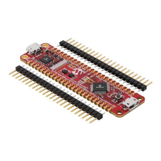
PIC24FJ64GU205 Curiosity Development Board Nano
Preface
The PIC24FJ64GU205 Curiosity Nano evaluation kit is a hardware platform to evaluate microcontrollers in the
PIC24FJGU205 family. This board has the PIC24FJ64GU205 microcontroller (MCU) mounted.
®
Supported by MPLAB
X IDE , the board provides easy access to the features of the PIC24FJ64GU205 to explore
how to integrate the device into a custom design.
The Curiosity Nano series of evaluation boards include an on-board debugger. No external tools are necessary to
program and debug the PIC24FJ64GU205.
®
•
MPLAB
X IDE
- Software to discover, configure, develop, program, and debug Microchip microcontrollers.
•
Code examples
- Get started with code examples.
•
PIC24FJ64GU205 website
•
PIC24FJ64GU205 Curiosity Nano website
©
2021 Microchip Technology Inc.
User's Guide
- Find documentation, data sheets, sample, and purchase microcontrollers.
- Kit information, latest user guide, and design documentation.
User Guide
50003124A-page 1
Advertisement
Table of Contents

Subscribe to Our Youtube Channel
Related Manuals for Microchip Technology Curiosity Nano PIC24FJ64GU205


Summary of Contents for Microchip Technology Curiosity Nano PIC24FJ64GU205
-
Page 1: Preface
- Get started with code examples. • PIC24FJ64GU205 website - Find documentation, data sheets, sample, and purchase microcontrollers. • PIC24FJ64GU205 Curiosity Nano website - Kit information, latest user guide, and design documentation. User Guide 50003124A-page 1 © 2021 Microchip Technology Inc. -
Page 2: Table Of Contents
3.5.2. Software Configuration....................19 3.5.3. Hardware Modifications....................20 3.5.4. Connecting to External Microcontrollers..............21 3.6. Connecting External Debuggers....................22 Hardware User Guide........................... 24 4.1. Connectors..........................24 4.1.1. PIC24FJ64GU205 Curiosity Nano Pinout..............24 User Guide 50003124A-page 2 © 2021 Microchip Technology Inc. - Page 3 Disconnecting the On-Board Debugger..................34 The Microchip Website..........................36 Product Change Notification Service......................36 Customer Support............................36 Microchip Devices Code Protection Feature....................36 Legal Notice..............................37 Trademarks..............................37 Quality Management System........................38 Worldwide Sales and Service........................39 User Guide 50003124A-page 3 © 2021 Microchip Technology Inc.
-
Page 4: Introduction
The Microchip PIC24FJ64GU205 Curiosity Nano evaluation kit is a hardware platform to evaluate the PIC24FJ64GU205 microcontroller. Figure 1-1. PIC24FJ64GU205 Curiosity Nano Board Overview Power/Status User LED Micro USB 32.768 kHz PIC24FJ64GU205 User Switch Micro USB PIC Debugger (LED0) Program/Debug Crystal Footprint (SW0) User Device Port User Guide 50003124A-page 4 © 2021 Microchip Technology Inc. -
Page 5: Getting Started
Microchip microcontrollers and digital signal controllers. It is named an Integrated Development Environment (IDE) because it provides a single integrated “environment” to develop code for embedded microcontrollers. User Guide 50003124A-page 5 © 2021 Microchip Technology Inc. - Page 6 Microchip development boards, ready to be adapted and extended. • PIC24FJ64GU205 Curiosity Nano website - Kit information, latest user guide, and design documentation. • PIC24FJ64GU205 Curiosity Nano on Microchip Direct - Purchase this kit on Microchip Direct. User Guide 50003124A-page 6 © 2021 Microchip Technology Inc.
-
Page 7: Curiosity Nano
The on-board debugger on the PIC24FJ64GU205 Curiosity Nano board appears as a Human Interface Device (HID) on the host computer’s USB subsystem. The debugger supports full-featured programming and debugging of the ® PIC24FJ64GU205 using MPLAB X IDE. User Guide 50003124A-page 7 © 2021 Microchip Technology Inc. -
Page 8: Virtual Serial Port (Cdc)
CDC. ® On Mac machines, the CDC will enumerate and appear as /dev/tty.usbmodem#. Depending on which terminal program is used, it will appear in the available list of modems as usbmodem#. User Guide 50003124A-page 8 © 2021 Microchip Technology Inc. -
Page 9: Limitations
To avoid any glitches resulting in unpredictable behavior like framing errors, the target device may enable the internal pull-up resistor on the pin connected to the debugger’s CDC TX pin. User Guide 50003124A-page 9 © 2021 Microchip Technology Inc. -
Page 10: Advanced Use
The on-board debugger includes a simple Mass Storage Device implementation, which is accessible for read/write operations via the host operating system to which it is connected. It provides: • Read access to basic text and HTML files for detailed kit information and support User Guide 50003124A-page 10 © 2021 Microchip Technology Inc. -
Page 11: Mass Storage Device Implementation
– the command handler reacts to content only. Table 3-2. Special File Commands Command Content Description CMD:ERASE Executes a chip erase of the target CMD:SEND_UART= Sends a string of characters to the CDC UART. See “CDC Override Mode.” User Guide 50003124A-page 11 © 2021 Microchip Technology Inc. -
Page 12: Data Gateway Interface (Dgi)
They are typically used to plot the occurrence of low-frequency events on a time-axis – for example, when certain application state transitions occur. The figure below shows the monitoring of the digital state of a mechanical switch connected to a debug GPIO in MPLAB Data Visualizer. User Guide 50003124A-page 12 © 2021 Microchip Technology Inc. -
Page 13: Timestamping
USB CDC TX line CDC RX UART TX USB CDC RX line DBG0 ICSPDAT Debug data line DBG1 ICSPCLK Debug clock line DBG2 GPIO0 debug GPIO0 DBG3 MCLR Reset line — No connect User Guide 50003124A-page 13 © 2021 Microchip Technology Inc. -
Page 14: Power Supply
Measure On/Off Target On/Off Debugger Power VUSB Adjust P3V3 Debugger Level GPIO Debugger Power consumer Regulator shifter straps Fuse Power converter Power protection Power source Cut strap VBUS #VOFF ID system User Guide 50003124A-page 14 © 2021 Microchip Technology Inc. -
Page 15: Target Regulator
100 mV over/under the set device voltage, an error condition will be flagged, and the target voltage regulator will be turned off. This will detect and handle any short-circuit conditions. It will also detect and handle if an User Guide 50003124A-page 15 © 2021 Microchip Technology Inc. -
Page 16: External Supply
PIC24FJ64GU205 Curiosity Nano has a VBUS output pin that can be used to power external components that need a 5V supply. The VBUS output pin has a PTC fuse to protect the USB against short circuits. A side effect of the PTC User Guide 50003124A-page 16 © 2021 Microchip Technology Inc. -
Page 17: Power Supply Exceptions
This can be caused by a full or partial short-circuit and is a special case of the issue mentioned above. Remove the short-circuit, and the on-board debugger will re-enable the on-board target voltage regulator. User Guide 50003124A-page 17 © 2021 Microchip Technology Inc. -
Page 18: Low-Power Measurement
Tri-states any I/O connected to the on-board debugger. 4.2. Sets the microcontroller in its lowest power sleep mode. Program the firmware into the PIC24FJ64GU205. Figure 3-7. Target Power Strap Target Power strap (top side) User Guide 50003124A-page 18 © 2021 Microchip Technology Inc. -
Page 19: Programming External Microcontrollers
Navigate to Tools > Options through the menu system at the top of the application. Select the Tools > Tool settings category in the options window. Set the Hide unsupported devices option to False. User Guide 50003124A-page 19 © 2021 Microchip Technology Inc. -
Page 20: Hardware Modifications
The on-board debugger is connected to the PIC24FJ64GU205 by default. Remove these connections before any external microcontroller can be programmed or debugged. Cut the GPIO straps shown in the figure below with a sharp tool to disconnect the PIC24FJ64GU205 from the on-board debugger. User Guide 50003124A-page 20 © 2021 Microchip Technology Inc. -
Page 21: Connecting To External Microcontrollers
Tie the VOFF pin to GND if the external hardware has a power supply • Make sure there are pull-down resistors on the ICSP data and clock signals (DBG0 and DBG1) to support the debugging of PIC microcontrollers User Guide 50003124A-page 21 © 2021 Microchip Technology Inc. -
Page 22: Connecting External Debuggers
Curiosity Nano to program/debug the PIC24FJ64GU205. The on-board debugger keeps all the pins connected to the PIC24FJ64GU205 and board edge in tri-state when not actively used. Therefore, the on-board debugger will not interfere with any external debug tools. User Guide 50003124A-page 22 © 2021 Microchip Technology Inc. - Page 23 To avoid contention between the external debugger and the on-board debugger, do not start any CAUTION ® programming/debug operation with the on-board debugger through MPLAB X IDE or mass storage programming while the external tool is active. User Guide 50003124A-page 23 © 2021 Microchip Technology Inc.
-
Page 24: Hardware User Guide
8 mil (~0.2 mm) off-center. The hole shift allows the use of regular 100 mil pin-headers on the board without soldering. Once the pin-headers are firmly in place, they can be used in normal applications like pin sockets and prototyping boards without any issues. User Guide 50003124A-page 24 © 2021 Microchip Technology Inc. -
Page 25: Peripherals
There is one yellow user LED available on the PIC24FJ64GU205 Curiosity Nano board that can be controlled by either GPIO or PWM. Driving the connected I/O line to GND can also activate the LED. User Guide 50003124A-page 25 © 2021 Microchip Technology Inc. -
Page 26: Mechanical Switch
Next, solder a blob on each of the circular solder points next to the crystal on the top side of the board as shown in the figure below. Table 4-3. Crystal Connections PIC24FJ64GU205 Function Shared Functionality SOSCO (Crystal output) Edge connector SOSCI (Crystal input) Edge connector Figure 4-4. Crystal Connection and Cut Straps User Guide 50003124A-page 26 © 2021 Microchip Technology Inc. -
Page 27: Target Usb Connector
Edge connector line) DBG0 ICSPDAT Edge connector DBG1 ICSPCLK Edge connector RA12 DBG2 SW0/GPIO Edge connector — DBG3 MCLR Edge connector VCC_Target VCC_LEVEL Supply voltage Edge connector Common ground Edge connector User Guide 50003124A-page 27 © 2021 Microchip Technology Inc. -
Page 28: Hardware Revision History And Known Issues
The serial number string has the following format: "nnnnrrssssssssss" n = product identifier r = revision s = serial number The product identifier for PIC24FJ64GU205 Curiosity Nano is A09-xxxx. User Guide 50003124A-page 28 © 2021 Microchip Technology Inc. -
Page 29: Document Revision History
Document Revision History Document Revision History Rev A Document (2/2021) Initial release of this document. User Guide 50003124A-page 29 © 2021 Microchip Technology Inc. -
Page 30: Appendix
Appendix Appendix Schematic Figure 7-1. PIC24FJ64GU205 Curiosity Nano Schematic User Guide 50003124A-page 30 © 2021 Microchip Technology Inc. - Page 31 Appendix User Guide 50003124A-page 31 © 2021 Microchip Technology Inc.
-
Page 32: Assembly Drawing
Appendix Assembly Drawing Figure 7-2. PIC24FJ64GU205 Curiosity Nano Assembly Drawing Top PIC® Figure 7-3. PIC24FJ64GU205 Curiosity Nano Assembly Drawing Bottom User Guide 50003124A-page 32 © 2021 Microchip Technology Inc. -
Page 33: Curiosity Nano Base For Click Boards
Appendix ™ Curiosity Nano Base for Click boards Figure 7-4. PIC24FJ64GU205 Curiosity Nano Pinout Mapping VBUS DBG3 RB14 RA10 RA11 VOFF DBG0 RB15 RB13 CDCTX DBG2 RA13 CDCRX DBG1 RA14 User Guide 50003124A-page 33 © 2021 Microchip Technology Inc. -
Page 34: Disconnecting The On-Board Debugger
PA04/PA06 DBG0 PA07 DBG1 PA08 DBG2 PA16 DBG3 Level-Shift TARGET PA00 CDC TX UART RX PA01 CDC RX UART TX DIR x 5 CDC RX DBG0 CDC TX DBG1 DBG2 DBG3 User Guide 50003124A-page 34 © 2021 Microchip Technology Inc. - Page 35 Appendix Figure 7-6. On-Board Debugger Connection Cut Straps GPIO straps (bottom side) Power Supply strap (top side) User Guide 50003124A-page 35 © 2021 Microchip Technology Inc.
-
Page 36: The Microchip Website
Attempts to break Microchip’s code protection feature may be a violation of the Digital Millennium Copyright Act. If such acts allow unauthorized access to your software or other copyrighted work, you may have a right to sue for relief under that Act. User Guide 50003124A-page 36 © 2021 Microchip Technology Inc. -
Page 37: Legal Notice
The Adaptec logo, Frequency on Demand, Silicon Storage Technology, and Symmcom are registered trademarks of Microchip Technology Inc. in other countries. GestIC is a registered trademark of Microchip Technology Germany II GmbH & Co. KG, a subsidiary of Microchip Technology Inc., in other countries. -
Page 38: Quality Management System
Quality Management System For information regarding Microchip’s Quality Management Systems, please visit www.microchip.com/quality. User Guide 50003124A-page 38 © 2021 Microchip Technology Inc. -
Page 39: Worldwide Sales And Service
New York, NY Tel: 46-31-704-60-40 Tel: 631-435-6000 Sweden - Stockholm San Jose, CA Tel: 46-8-5090-4654 Tel: 408-735-9110 UK - Wokingham Tel: 408-436-4270 Tel: 44-118-921-5800 Canada - Toronto Fax: 44-118-921-5820 Tel: 905-695-1980 Fax: 905-695-2078 User Guide 50003124A-page 39 © 2021 Microchip Technology Inc.
Need help?
Do you have a question about the Curiosity Nano PIC24FJ64GU205 and is the answer not in the manual?
Questions and answers