Table of Contents
Advertisement
Quick Links
PIC16F17146 CNANO Hardware User Guide
Preface
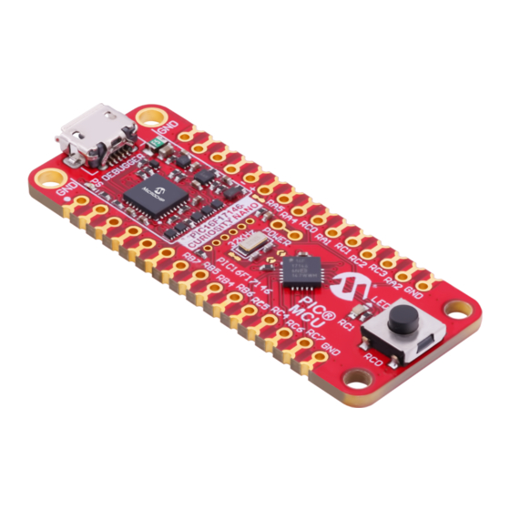
The PIC16F17146 Curiosity Nano evaluation kit is a hardware platform to evaluate microcontrollers in the
PIC16F17146 family. This board has the PIC16F17146 microcontroller (MCU) mounted.
®
Supported by MPLAB
X IDE, the board provides easy access to the features of the PIC16F17146 to explore how to
integrate the device into a custom design.
The Curiosity Nano series of evaluation boards include an on-board debugger. No external tools are necessary to
program and debug the PIC16F17146.
®
•
MPLAB
X IDE
- Software to discover, configure, develop, program, and debug Microchip microcontrollers.
•
Code examples on GitHub
•
PIC16F17146 website
•
PIC16F17146 Curiosity Nano website
©
2022 Microchip Technology Inc.
and its subsidiaries
PIC16F17146 CNANO
- Get started with code examples.
- Find documentation, data sheets, sample, and purchase microcontrollers.
- Kit information, latest user guide, and design documentation.
User Guide
DS50003388A-page 1
Advertisement
Table of Contents

Related Manuals for Microchip Technology PIC16F17146 CNANO


Summary of Contents for Microchip Technology PIC16F17146 CNANO
-
Page 1: Preface
PIC16F17146 CNANO PIC16F17146 CNANO Hardware User Guide Preface The PIC16F17146 Curiosity Nano evaluation kit is a hardware platform to evaluate microcontrollers in the PIC16F17146 family. This board has the PIC16F17146 microcontroller (MCU) mounted. ® Supported by MPLAB X IDE, the board provides easy access to the features of the PIC16F17146 to explore how to integrate the device into a custom design. -
Page 2: Table Of Contents
3.5.1. Supported Devices...................... 20 3.5.2. Software Configuration....................20 3.5.3. Hardware Modifications....................21 3.5.4. Connecting to External Microcontrollers..............22 3.6. Connecting External Debuggers....................23 Hardware Description..........................25 4.1. Connectors..........................25 User Guide DS50003388A-page 2 © 2022 Microchip Technology Inc. and its subsidiaries... - Page 3 The Microchip Website..........................39 Product Change Notification Service....................39 Customer Support..........................39 Microchip Devices Code Protection Feature..................39 Legal Notice............................39 Trademarks............................40 Quality Management System........................ 41 Worldwide Sales and Service........................42 User Guide DS50003388A-page 3 © 2022 Microchip Technology Inc. and its subsidiaries...
-
Page 4: Introduction
– 500 mA maximum output current (limited by ambient temperature and output voltage) Board Overview The Microchip PIC16F17146 Curiosity Nano evaluation kit is a hardware platform to evaluate the PIC16F17146 microcontroller. User Guide DS50003388A-page 4 © 2022 Microchip Technology Inc. and its subsidiaries... - Page 5 PIC16F17146 CNANO Introduction Figure 1-1. PIC16F17146 Curiosity Nano Board Overview User Guide DS50003388A-page 5 © 2022 Microchip Technology Inc. and its subsidiaries...
-
Page 6: Getting Started
X IDE will present relevant information like data sheets and board documentation. ® Tip: If closed, reopen the Kit Window in MPLAB X IDE through the menu bar Window > Kit Window. User Guide DS50003388A-page 6 © 2022 Microchip Technology Inc. and its subsidiaries... -
Page 7: Design Documentation And Relevant Links
• PIC16F17146 Curiosity Nano website - Kit information, latest user guide, and design documentation. • PIC16F17146 Curiosity Nano on Microchip Direct - Purchase this kit on Microchip Direct. User Guide DS50003388A-page 7 © 2022 Microchip Technology Inc. and its subsidiaries... -
Page 8: Curiosity Nano
The on-board debugger on the PIC16F17146 Curiosity Nano board appears as a Human Interface Device (HID) on the host computer’s USB subsystem. The debugger supports full-featured programming and debugging of the ® PIC16F17146 using MPLAB X IDE. User Guide DS50003388A-page 8 © 2022 Microchip Technology Inc. and its subsidiaries... -
Page 9: Virtual Serial Port (Cdc)
On Mac machines, the CDC will enumerate and appear as /dev/tty.usbmodem#. Depending on the terminal program used, it will appear in the available list of modems as usbmodem#. User Guide DS50003388A-page 9 © 2022 Microchip Technology Inc. and its subsidiaries... -
Page 10: Limitations
CDC TX pin to avoid glitches resulting in unpredictable behavior like framing errors. User Guide DS50003388A-page 10 © 2022 Microchip Technology Inc. and its subsidiaries... -
Page 11: Advanced Use
A break character is defined as a sequence of at least 11 zero bits transmitted from the host to the device. User Guide DS50003388A-page 11 © 2022 Microchip Technology Inc. and its subsidiaries... -
Page 12: Mass Storage Device
KIT-INFO.TXT – a text file containing details about the board’s debugger firmware version, board name, USB serial number, device, and drag-and-drop support • STATUS.TXT – a text file containing the programming status of the board User Guide DS50003388A-page 12 © 2022 Microchip Technology Inc. and its subsidiaries... -
Page 13: Configuration Words
(Debugger firmware v1.16 or newer.) Info: The content sent to the mass storage emulated disk triggers the commands listed here and provides no feedback in the case of either success or failure. User Guide DS50003388A-page 13 © 2022 Microchip Technology Inc. and its subsidiaries... -
Page 14: Data Gateway Interface (Dgi)
The 12 edge connections closest to the USB connector on Curiosity Nano boards have a standardized pinout. The program/debug pins have different functions depending on the target programming interface, as shown in the table and figure below. User Guide DS50003388A-page 14 © 2022 Microchip Technology Inc. and its subsidiaries... -
Page 15: Power Supply
4.4V and 5.25V (according to the USB specification) and will limit the maximum voltage supplied to the target. The figure below shows the entire power supply system on PIC16F17146 Curiosity Nano. User Guide DS50003388A-page 15 © 2022 Microchip Technology Inc. and its subsidiaries... -
Page 16: Target Regulator
The maximum current load depends on the input voltage, the selected output voltage, and the ambient temperature. The figure below shows the safe operating area for the regulator, with an input voltage of 5.1V and an ambient temperature of 23°C. User Guide DS50003388A-page 16 © 2022 Microchip Technology Inc. and its subsidiaries... -
Page 17: External Supply
The absolute maximum external voltage is 5.5V for the on-board level shifters, and the standard operating WARNING condition of the PIC16F17146 is 1.8–5.5V. Applying a higher voltage may cause permanent damage to the board. User Guide DS50003388A-page 17 © 2022 Microchip Technology Inc. and its subsidiaries... -
Page 18: Vbus Output Pin
VBUS output. Figure 3-6. VBUS Output Voltage vs. Current 3.3.4 Power Supply Exceptions This chapter sums up most exceptions that can occur with the power supply. User Guide DS50003388A-page 18 © 2022 Microchip Technology Inc. and its subsidiaries... -
Page 19: Low-Power Measurement
Connect an ammeter to the pin header. Write firmware that: Tri-states any I/O connected to the on-board debugger. Sets the microcontroller in its lowest Power sleep mode. Program the firmware into the PIC16F17146. User Guide DS50003388A-page 19 © 2022 Microchip Technology Inc. and its subsidiaries... -
Page 20: Programming External Microcontrollers
PIC16F17146 Curiosity Nano can program and debug external PIC16F17146 microcontrollers with MPLAB X IDE. 3.5.2 Software Configuration No software configuration is required to program and debug the same device mounted on the board. User Guide DS50003388A-page 20 © 2022 Microchip Technology Inc. and its subsidiaries... -
Page 21: Hardware Modifications
The on-board debugger is connected to the PIC16F17146 by default. Remove these connections before any external microcontroller can be programmed or debugged. Cut the GPIO straps shown in the figure below with a sharp tool to disconnect the PIC16F17146 from the on-board debugger. User Guide DS50003388A-page 21 © 2022 Microchip Technology Inc. and its subsidiaries... -
Page 22: Connecting To External Microcontrollers
Tie the VOFF pin to GND if the external hardware has a power supply • Make sure there are pull-down resistors on the ICSP data and clock signals (DBG0 and DBG1) to support the debugging of PIC microcontrollers User Guide DS50003388A-page 22 © 2022 Microchip Technology Inc. and its subsidiaries... -
Page 23: Connecting External Debuggers
Curiosity Nano to program/debug the PIC16F17146. When not actively used, the on-board debugger keeps all the pins connected to the PIC16F17146 and board edge in tri-state. Therefore, the on-board debugger will not interfere with any external debug tools. User Guide DS50003388A-page 23 © 2022 Microchip Technology Inc. and its subsidiaries... - Page 24 To avoid contention between the external debugger and the on-board debugger, do not start any CAUTION ® programming/debug operation with the on-board debugger through MPLAB X IDE or mass storage programming while the external tool is active. User Guide DS50003388A-page 24 © 2022 Microchip Technology Inc. and its subsidiaries...
-
Page 25: Hardware Description
(~0.2 mm) off-center. The hole shift allows regular 100 mil pin-headers to be used without soldering on the board. The pin-headers can be used in applications like pin sockets and prototyping boards without issues once they are firmly in place. User Guide DS50003388A-page 25 © 2022 Microchip Technology Inc. and its subsidiaries... -
Page 26: Peripherals
Important: Once the pin-headers are in place, they are hard to remove by hand. Use a set of pliers and carefully remove the pin-headers to avoid damage to the pin-headers and PCB. Peripherals User Guide DS50003388A-page 26 © 2022 Microchip Technology Inc. and its subsidiaries... -
Page 27: Led
Figure 4-4 shows the cut straps and solder points. Table 4-3. Crystal Connections PIC16F17146 Pin Function Shared Functionality SOSCO (Crystal output) Edge connector SOSCI (Crystal input) Edge connector User Guide DS50003388A-page 27 © 2022 Microchip Technology Inc. and its subsidiaries... -
Page 28: On-Board Debugger Implementation
Edge connector line) CDC RX EUSART1 TX (PIC16F17146 TX Edge connector line) DBG0 ICSPDAT Edge connector DBG1 ICSPCLK Edge connector DBG2 SW0/GPIO Edge connector DBG3 MCLR Edge connector User Guide DS50003388A-page 28 © 2022 Microchip Technology Inc. and its subsidiaries... -
Page 29: Hardware Revision History And Known Issues
= product identifier r = revision s = serial number The product identifier for PIC16F17146 Curiosity Nano is A09-3434. Revision 3 Revision 3 is the initially released board revision. User Guide DS50003388A-page 29 © 2022 Microchip Technology Inc. and its subsidiaries... -
Page 30: Document Revision History
PIC16F17146 CNANO Document Revision History Document Revision History Doc. Rev. Date Comments 08/2022 Initial document release User Guide DS50003388A-page 30 © 2022 Microchip Technology Inc. and its subsidiaries... -
Page 31: Appendix
PIC16F17146 CNANO Appendix Appendix User Guide DS50003388A-page 31 © 2022 Microchip Technology Inc. and its subsidiaries... - Page 32 Figure 7-1. PIC16F17146 Curiosity Nano MCU Schematic rotatethispage90 PIC16F17146 PIC16F17146 DEBUGGER CONNECTIONS CDC_RX Debugger Name CDC_RX CDC_TX CDC_TX CDC TX EUSART1 RX DBG0 CDC RX DBG3 EUSART1 TX DBG1 DBG0 DBG2 ICSPDAT C200 VOFF DBG1 ICSPCLK ID_SYS VCC_TARGET 100n DBG2 GPIO0 PROG/DEBUG Pull DBG3...
- Page 33 Figure 7-2. PIC16F17146 Curiosity Nano Debugger Schematic rotatethispage90 Interface ICSP UPDI TARGET ADJUSTABLE REGULATOR TARGET TARGET Signal VCC_VBUS J100: VCC_REGULATOR VCC_LEVEL VCC_EDGE CDC TX UART RX UART RX - Cut-strap used for full separation of target power from the level shifters and on-board regulators. U102 MIC5353 U108...
-
Page 34: Assembly Drawing
PIC16F17146 CNANO Appendix Assembly Drawing Figure 7-3. PIC16F17146 Curiosity Nano Assembly Drawing Top User Guide DS50003388A-page 34 © 2022 Microchip Technology Inc. and its subsidiaries... - Page 35 PIC16F17146 CNANO Appendix Figure 7-4. PIC16F17146 Curiosity Nano Assembly Drawing Bottom User Guide DS50003388A-page 35 © 2022 Microchip Technology Inc. and its subsidiaries...
-
Page 36: Curiosity Nano Base For Click Boards
PIC16F17146 CNANO Appendix ™ Curiosity Nano Base for Click boards Figure 7-5. PIC16F17146 Curiosity Nano Pinout Mapping User Guide DS50003388A-page 36 © 2022 Microchip Technology Inc. and its subsidiaries... -
Page 37: Disconnecting The On-Board Debugger
DBG1 PA08 DBG2 PA16 DBG3 Level-Shift TARGET PA00 CDC TX UART RX PA01 CDC RX UART TX DIR x 5 CDC RX DBG0 CDC TX DBG1 DBG2 DBG3 User Guide DS50003388A-page 37 © 2022 Microchip Technology Inc. and its subsidiaries... - Page 38 PIC16F17146 CNANO Appendix Figure 7-7. On-Board Debugger Connection Cut Straps GPIO straps (bottom side) Power Supply strap (top side) User Guide DS50003388A-page 38 © 2022 Microchip Technology Inc. and its subsidiaries...
-
Page 39: Microchip Information
Microchip products with your application. Use of this information in any other manner violates these terms. Information regarding device applications is provided only for your convenience and may be superseded User Guide DS50003388A-page 39 © 2022 Microchip Technology Inc. and its subsidiaries... -
Page 40: Trademarks
The Adaptec logo, Frequency on Demand, Silicon Storage Technology, and Symmcom are registered trademarks of Microchip Technology Inc. in other countries. GestIC is a registered trademark of Microchip Technology Germany II GmbH & Co. KG, a subsidiary of Microchip Technology Inc., in other countries. -
Page 41: Quality Management System
PIC16F17146 CNANO Quality Management System For information regarding Microchip’s Quality Management Systems, please visit www.microchip.com/quality. User Guide DS50003388A-page 41 © 2022 Microchip Technology Inc. and its subsidiaries... -
Page 42: Worldwide Sales And Service
Tel: 631-435-6000 Sweden - Stockholm San Jose, CA Tel: 46-8-5090-4654 Tel: 408-735-9110 UK - Wokingham Tel: 408-436-4270 Tel: 44-118-921-5800 Canada - Toronto Fax: 44-118-921-5820 Tel: 905-695-1980 Fax: 905-695-2078 User Guide DS50003388A-page 42 © 2022 Microchip Technology Inc. and its subsidiaries...
Need help?
Do you have a question about the PIC16F17146 CNANO and is the answer not in the manual?
Questions and answers