Table of Contents
Advertisement
Quick Links
PIC18F47Q10 Curiosity Nano
PIC18F47Q10 Curiosity Nano Hardware User Guide
Preface
The PIC18F47Q10 Curiosity Nano evaluation kit is a hardware platform to evaluate the PIC18F47Q10
microcontroller.
®
Supported by MPLAB
X Integrated Development Environment (IDE), the kit provides easy access to the
features of the PIC18F47Q10 and explains how to integrate the device into a custom design.
The Curiosity Nano series of evaluation kits include an on-board debugger, and no external tools are
necessary to program the PIC18F47Q10.
User Guide
DS40002103A-page 1
©
2019 Microchip Technology Inc.
Advertisement
Table of Contents

Related Manuals for Microchip Technology PIC18F47Q10 Curiosity Nano


Summary of Contents for Microchip Technology PIC18F47Q10 Curiosity Nano
-
Page 1: Preface
PIC18F47Q10 Curiosity Nano PIC18F47Q10 Curiosity Nano Hardware User Guide Preface The PIC18F47Q10 Curiosity Nano evaluation kit is a hardware platform to evaluate the PIC18F47Q10 microcontroller. ® Supported by MPLAB X Integrated Development Environment (IDE), the kit provides easy access to the features of the PIC18F47Q10 and explains how to integrate the device into a custom design. -
Page 2: Table Of Contents
PIC18F47Q10 Curiosity Nano Table of Contents Preface..........................1 1. Introduction........................3 2. Getting Started......................4 3. Curiosity Nano......................5 4. Hardware User Guide....................13 5. Hardware Revision History..................16 6. Document Revision History..................17 7. Appendix........................18 The Microchip Web Site....................22 Customer Change Notification Service................22 Customer Support...................... -
Page 3: Introduction
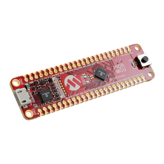
– 1.8-5.1V output voltage (limited by USB input voltage) – 500 mA maximum output current (limited by ambient temperature and output voltage) Kit Overview The Microchip PIC18F47Q10 Curiosity Nano evaluation kit is a hardware platform to evaluate the PIC18F47Q10 microcontroller. Figure 1-1. PIC18F47Q10 Curiosity Nano Evaluation Kit Overview 32.768 kHz... -
Page 4: Getting Started
Curiosity Nano and Xplained Pro boards and COM Ports. • PIC18F47Q10 Curiosity Nano website - Kit information, latest user guide and design documentation. • PIC18F47Q10 Curiosity Nano on Microchip Direct - Purchase this kit on Microchip Direct. User Guide DS40002103A-page 4 © 2019 Microchip Technology Inc. -
Page 5: Curiosity Nano
Data Gateway Interface (DGI) GPIO. On-Board Debugger The PIC18F47Q10 Curiosity Nano contains an on-board debugger for programming and debugging. The on-board debugger is a composite USB device of several interfaces: a debugger, a mass storage device, a data gateway, and a Virtual COM port (CDC). - Page 6 PIC18F47Q10 Curiosity Nano Curiosity Nano On Linux machines, the CDC will enumerate and appear as /dev/ttyACM#. On MAC machines, the CDC will enumerate and appear as /dev/tty.usbmodem#. Depending on which terminal program is used, it will appear in the available list of modems as usbmodem#.
- Page 7 PIC18F47Q10 Curiosity Nano Curiosity Nano also pushed to the USB queue at approximately 100 ms intervals, triggered by USB start-of-frame tokens. Up to 8 x 64-byte frames can be active at any time. If the host, or the software running on it, fails to receive data fast enough, an overrun will occur. When this happens, the last-filled buffer frame will be recycled instead of being sent to the USB queue, and a full frame of data will be lost.
- Page 8 PIC18F47Q10 Curiosity Nano Curiosity Nano 3.1.2.2 Configuration Words/Fuse Bytes ® Configuration Words (PIC MCU Targets) Configuration Word settings included in the project being programmed after program Flash is programmed. The debugger will not mask out any bits in the Configuration Words when writing them, but since it uses Low-Voltage Programming mode, it is unable to clear the LVP Configuration bit.
- Page 9 The voltage from the USB connector can vary between 4.4V to 5.25V (according to the USB specification) and will limit the maximum voltage to the target. The figure below shows the entire power supply system on PIC18F47Q10 Curiosity Nano. Figure 3-2. Power Supply Block Diagram 3.3.1...
- Page 10 VBUS Output Pin PIC18F47Q10 Curiosity Nano has a VBUS output pin which can be used to power external components that need a 5V supply. The VBUS output pin has a PTC fuse to protect the USB against short circuits. A side effect of the PTC fuse is a voltage drop on the VBUS output with higher current loads.
- Page 11 PIC18F47Q10 Curiosity Nano Curiosity Nano Figure 3-4. VBUS output voltage vs current Disconnecting the On-Board Debugger The block diagram below shows all connections between the debugger and the PIC18F47Q10 microcontroller. The rounded boxes represent connections to the board edge on PIC18F47Q10 Curiosity Nano.
- Page 12 PIC18F47Q10 Curiosity Nano Curiosity Nano Info: Cutting the connections to the debugger will disable programming, debugging, data streaming, and the target power supply. The signals will also be disconnected from the board edge next to the on-board debugger section. Info: Solder in 0Ω resistors across the footprints or short-circuit them with tin solder to reconnect any cut signals.
-
Page 13: Hardware User Guide
LED0 Peripherals 4.2.1 There is one yellow user LED available on the PIC18F47Q10 Curiosity Nano kit that can be controlled by either GPIO or PWM. The LED can be activated by driving the connected I/O line to GND. User Guide DS40002103A-page 13 ©... - Page 14 Edge connector 4.2.4 On-Board Debugger Implementation PIC18F47Q10 Curiosity Nano features an on-board debugger that can be used to program and debug the PIC18F47Q10 using ICSP. The on-board debugger also includes a Virtual Com port interface over ® UART and DGI GPIO. MPLAB X can be used as a front-end for the on-board debugger for programming and debugging.
- Page 15 PIC18F47Q10 Curiosity Nano Hardware User Guide Table 4-4. On-Board Debugger Connections PIC18F47Q10 Debugger Pin Function Shared Functionality CDC TX UART RX (PIC18F47Q10 RX Edge connector line) CDC RX UART TX (PIC18F47Q10 TX Edge connector line) DBG0 ICSPDAT Edge connector DBG1 ICSPCLK...
-
Page 16: Hardware Revision History
Identifying Product ID and Revision The revision and product identifier of the PIC18F47Q10 Curiosity Nano can be found in two ways; either ®... -
Page 17: Document Revision History
PIC18F47Q10 Curiosity Nano Document Revision History Document Revision History Doc. rev. Date Comment 03/2019 Initial document release. User Guide DS40002103A-page 17 © 2019 Microchip Technology Inc. -
Page 18: Appendix
PIC18F47Q10 Curiosity Nano Appendix Appendix Schematic Figure 7-1. PIC18F47Q10 Curiosity Nano Schematic User Guide DS40002103A-page 18 © 2019 Microchip Technology Inc. - Page 19 PIC18F47Q10 Curiosity Nano Appendix User Guide DS40002103A-page 19 © 2019 Microchip Technology Inc.
- Page 20 PIC18F47Q10 Curiosity Nano Appendix ™ Curiosity Nano Base for click Boards Figure 7-2. PIC18F47Q10 Curiosity Nano pinout mapping VBUS VOFF DBG3 DBG0 GND (RC1) (RC0) ID CDC RX CDC TX DBG1 DBG2 User Guide DS40002103A-page 20 © 2019 Microchip Technology Inc.
- Page 21 Even though there is an on-board debugger, external debuggers can be connected directly to PIC18F47Q10 Curiosity Nano to program/debug the PIC18F47Q10. The on-board debugger keeps all the pins connected to the PIC18F47Q10 and board edge in tri-state when not actively used. Therefore, the on-board debugger will not interfere with any external debug tools.
-
Page 22: The Microchip Web Site
PIC18F47Q10 Curiosity Nano The Microchip Web Site Microchip provides online support via our web site at http://www.microchip.com/. This web site is used as a means to make files and information easily available to customers. Accessible by using your favorite Internet browser, the web site contains the following information: •... -
Page 23: Legal Notice
SQTP is a service mark of Microchip Technology Incorporated in the U.S.A. Silicon Storage Technology is a registered trademark of Microchip Technology Inc. in other countries. GestIC is a registered trademark of Microchip Technology Germany II GmbH & Co. KG, a subsidiary of Microchip Technology Inc., in other countries. -
Page 24: Quality Management System Certified By Dnv
PIC18F47Q10 Curiosity Nano © 2019, Microchip Technology Incorporated, Printed in the U.S.A., All Rights Reserved. ISBN: 978-1-5224-4372-8 Quality Management System Certified by DNV ISO/TS 16949 Microchip received ISO/TS-16949:2009 certification for its worldwide headquarters, design and wafer fabrication facilities in Chandler and Tempe, Arizona; Gresham, Oregon and design centers in California ®... -
Page 25: Worldwide Sales And Service
New York, NY Sweden - Stockholm Tel: 631-435-6000 Tel: 46-8-5090-4654 San Jose, CA UK - Wokingham Tel: 408-735-9110 Tel: 44-118-921-5800 Tel: 408-436-4270 Fax: 44-118-921-5820 Canada - Toronto Tel: 905-695-1980 Fax: 905-695-2078 User Guide DS40002103A-page 25 © 2019 Microchip Technology Inc.
Need help?
Do you have a question about the PIC18F47Q10 Curiosity Nano and is the answer not in the manual?
Questions and answers