Table of Contents
Advertisement
Quick Links
1.0
INTRODUCTION
The PCI11414 Quick Start Guide provides a visual view of step-by-step procedures used to exercise each peripheral
system available in EVB-PCI11414. The PCI11414 is a PCIe
and 3.1 Gen2), and UART. The versatile nature of this product makes it ideal for embedded systems and industrial appli-
cations.
Detailed information is included in the following sections:
•
Section 2.0, General Considerations
•
Section 3.0, Board Setup
•
Section 4.0, Programming the Board
•
Section 5.0, Verifying Hardware
2.0
GENERAL CONSIDERATIONS
2.1
Required References
The PCI11414 implementor should have the following documents on hand:
• EVB-PCI11414 Evaluation Board User's Guide
• AN5104 MPLab Connect PCI1XXXX Options
2.2
Hardware Requirements and Setup
All the hardware devices mentioned in this quick start guide can be acquired using their part numbers from
www.microchipdirect.com. Below is a required device:
• EVB-PCI11414 Evaluation Board
2.3
Software Requirements
The following software programs are required for carrying out the procedures in this guide:
®
• Drivers. Linux
Kernel 6.1.0 is used in conjunction with the drivers below to verify the functionality of the
PCI11414. The latest drivers are mainlined into the Linux 6.1.x kernel and can additionally be found on the
PCI11414 product page.
- GP_Driver V1.0.0 or newer
2
- I
C_Driver V1.0.0 or newer
- SPI_Driver V1.0.0 or newer
- UART_Driver V1.0.0 or newer
• SW Packages
- Spi_driver_tools (must be compiled):
2
- I
C tools
- Minicom (built into Linux)
- Pymodslave (can be installed with pip install pyModSlave, which only works through Python 3.9)
- Gmodmaster (can be downloaded from https://sourceforge.net/projects/qmodmaster/)
2023 Microchip Technology Inc. and its subsidiaries
®
Linux
Quick Start Guide
®
bridge that supports SPI, I
PCI11414
2
C, GPIO, Ethernet, USB (2.0
DS50003610A-page 1
Advertisement
Table of Contents

Related Manuals for Microchip Technology PCI11414


Summary of Contents for Microchip Technology PCI11414
- Page 1 • Drivers. Linux Kernel 6.1.0 is used in conjunction with the drivers below to verify the functionality of the PCI11414. The latest drivers are mainlined into the Linux 6.1.x kernel and can additionally be found on the PCI11414 product page.
-
Page 2: Board Setup
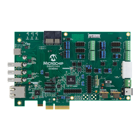
PCI11414 BOARD SETUP Figure 3-1 shows the EVB-PCI11414 Evaluation Board. FIGURE 3-1: EVB-PCI11414 EVALUATION BOARD 2023 Microchip Technology Inc. and its subsidiaries DS50003610A-page 2... -
Page 3: Programming The Board
Perform the following procedure to enable EEPROM to be programmed: Verify if there is a jumper on J8. This jumper enables the EEPROM. This allows the EEPROM to be programmed and enables the EVB-PCI11414 to load the configuration from the EEPROM. (See Figure 4-1.) - Page 4 Plug in an I C programmer (an Aardvark is used in this guide) to header J13. ® Open Flash Center for Windows . The PCI11414 configuration can be both read and written to from this appli- cation. (See Figure 4-2.)
- Page 5 ADDING ADAPTERS ON FLASH CENTER Plug in the Aardvark and click on Refresh. When the device shows up, select it and click on Add. (See Figure 4- FIGURE 4-4: ADDING THE ADAPTER 2023 Microchip Technology Inc. and its subsidiaries DS50003610A-page 5...
- Page 6 PCI11414 Select Choose Target. (See Figure 4-5.) FIGURE 4-5: FLASH CENTER TARGET 2023 Microchip Technology Inc. and its subsidiaries DS50003610A-page 6...
- Page 7 Configure the following settings as shown in Figure 4-7: • Bit rate is 400 kHz. • I C Slave Address is left as default. • Target power is disabled. • IO power is disabled. 2023 Microchip Technology Inc. and its subsidiaries DS50003610A-page 7...
- Page 8 PCI11414 FIGURE 4-7: FLASH CENTER CONFIGURATION Click on Erase Device. Select Entire Device and then click on OK. (See Figure 4-8.) FIGURE 4-8: ERASING DEVICE 2023 Microchip Technology Inc. and its subsidiaries DS50003610A-page 8...
- Page 9 Verify if the device was erased by reading the EEPROM back in. A successful erase will show all 0’s. Refer to Figure 4-9. FIGURE 4-9: SUCCESSFUL ERASE 10. Go to File>Load File. See Figure 4-10. FIGURE 4-10: FLASH CENTER LOAD FILE 2023 Microchip Technology Inc. and its subsidiaries DS50003610A-page 9...
- Page 10 11. Change the file type to Binary Files (“.”). Navigate to the configuration binary file and select it. See Figure 4-11. The contents of the binary file will appear in the Data window as indicated in Figure 4-12. FIGURE 4-11: LOADING BINARY IMAGE FIGURE 4-12: BINARY FILE CONTENT 2023 Microchip Technology Inc. and its subsidiaries DS50003610A-page 10...
- Page 11 EEPROM. Note that elevated privileges may be required to run the command. Power cycle the PC for the changes to take effect. 2023 Microchip Technology Inc. and its subsidiaries DS50003610A-page 11...
-
Page 12: Verifying Hardware
VERIFYING HARDWARE Follow the succeeding procedure to verify the hardware: ® With the PC turned off, insert the EVB-PCI11414 into one of the PCIe slots. Power on the PC. Make sure to boot into the correct kernel. Open a terminal window (CTRL+ALT+T) and run the command lspci. Verify if the output shows five PCI bridges from Microchip. - Page 13 1 or 2 depending on which way the device is plugged in. Refer to the image in Figure 5-3 for the position of the ports on the EVB board. FIGURE 5-3: USB PORT LOCATIONS 2023 Microchip Technology Inc. and its subsidiaries DS50003610A-page 13...
- Page 14 • Connect T1 to R1. • Connect T2 to R2. • Connect R1 to T1. • Connect R2 to T2. Refer to the board image in Figure 5-5 and the schematics in Figure 5-6. 2023 Microchip Technology Inc. and its subsidiaries DS50003610A-page 14...
- Page 15 PCI11414 FIGURE 5-5: WIRED UARTS FIGURE 5-6: UART SCHEMATIC DRAWING 2023 Microchip Technology Inc. and its subsidiaries DS50003610A-page 15...
- Page 16 Create a new session for each port listed in Figure 5-8. FIGURE 5-8: SAMPLE PUTTY SESSION Start typing into each session. If UART is working correctly, you will see what you type as output in a different session. 2023 Microchip Technology Inc. and its subsidiaries DS50003610A-page 16...
-
Page 17: Establishing Communication
RS-485 and RS-232 use the same UART pins, this command will show the same output that was shown in the RS-232 steps. Next, configure the PC to use RS-485. This can be done with minicom. Run minicom -D /dev/ttyS<PORT NUMBER>. See Figure 5-10. 2023 Microchip Technology Inc. and its subsidiaries DS50003610A-page 17... - Page 18 PCI11414 FIGURE 5-10: MINICOM WELCOME SCREEN Bring up the command summary by pressing ctrl-A and then Z. (See Figure 5-11.) FIGURE 5-11: MINICOM COMMAND SUMMARY 2023 Microchip Technology Inc. and its subsidiaries DS50003610A-page 18...
- Page 19 PCI11414 Press O to enter the configuration menu. See Figure 5-12. FIGURE 5-12: MINICOM CONFIGURATION MENU Select Serial port setup. See Figure 5-13. FIGURE 5-13: MINICOM SERIAL PORT SETUP 2023 Microchip Technology Inc. and its subsidiaries DS50003610A-page 19...
-
Page 20: Modbus Rtu
Start pyModSlave with sudo python3 pyModSlave. This will bring up a GUI. See Figure 5-14. FIGURE 5-14: PYMODSLAVE Go to Options>Modbus RTU to configure the connection settings. See Figure 5-15. FIGURE 5-15: MODBUS RTU 2023 Microchip Technology Inc. and its subsidiaries DS50003610A-page 20... - Page 21 12. Click on Connect. The same number of coils set in the previous step will appear. These can be changed manually or randomly by selecting the sim checkbox. (See Figure 5-17.) FIGURE 5-17: PYMODSLAVE READ 2023 Microchip Technology Inc. and its subsidiaries DS50003610A-page 21...
- Page 22 Connect the RS-485<->USB cable to the PC and open qModMaster. Note that drivers for the cable may need to be installed in the PC. (See Figure 5-18.) FIGURE 5-18: QMODMASTER Go to Options>Modbus RTU. (See Figure 5-19.) FIGURE 5-19: QMODMASTER RTU 2023 Microchip Technology Inc. and its subsidiaries DS50003610A-page 22...
- Page 23 Change the slave address and number of coils to match what was set up on the host computer and click on Con- nect. (See Figure 5-21.) FIGURE 5-21: QMODMASTER CONNECTED 2023 Microchip Technology Inc. and its subsidiaries DS50003610A-page 23...
- Page 24 First, verify that if the GPIO bank can be seen. Run gpiodetect. Note that elevated privileges may be required. Look for an entry labeled mchp_pci1xxxx_gp.gp. Note that the number after gpiochip is the bank number. In this case, it is bank 0. See Figure 5-23. FIGURE 5-23: GPIODETECT 2023 Microchip Technology Inc. and its subsidiaries DS50003610A-page 24...
- Page 25 Figure 5-25. Connect pin 67 to ground again and note the falling edge. Disconnect the ground and note the rising edge. See Figure 5-26. 2023 Microchip Technology Inc. and its subsidiaries DS50003610A-page 25...
-
Page 26: Setting Outputs
67 was already reading a 1 prior to this command. 2=0. Note the change in the monitoring window. See Figure 5-27. gpioset 0 FIGURE 5-27: GPIO INPUT AND OUTPUT 2023 Microchip Technology Inc. and its subsidiaries DS50003610A-page 26... - Page 27 Connect the SCL, SDA, and ground lines from the Aardvark to header J12. Plug the USB cable into a Windows PC. See Figure 5-29. FIGURE 5-29: I2C, SCL, SDA, AND GROUND LINES 2023 Microchip Technology Inc. and its subsidiaries DS50003610A-page 27...
-
Page 28: Control Center
Open the Control Center. See Figure 5-30. FIGURE 5-30: CONTROL CENTER To bring up the list of available adapters, click on Adapter>Connect. See Figure 5-31. FIGURE 5-31: CONTROL CENTER ADAPTER LIST 2023 Microchip Technology Inc. and its subsidiaries DS50003610A-page 28... - Page 29 In the I C Control Panel, select Slave. Set address 0x31 and then click on Enable. To set the message read by PCI11414, type a message (in hex) in the message window and then click on Set Resp. See Figure 5-33 Figure 5-34.
- Page 30 C SLAVE CONFIGURATION To list all I C devices connected to the computer that the EVB-PCI11414 is attached to, open a terminal and run -l. This will show the assigned device name as I C-<DEVICE NUMBER> for each device as well i2cdetect as the name.
- Page 31 Note that this command may need to be run with elevated privileges. If prompted to continue, type “y” and press enter. See Figure 5-37. FIGURE 5-37: CDUMP 11. This command will output the message that was set earlier in the Command Center. 2023 Microchip Technology Inc. and its subsidiaries DS50003610A-page 31...
-
Page 32: Documentation Conventions
Choice of mutually exclusive argu- errorlevel {0|1} character: { | } ments; an OR selection Ellipses... Replaces repeated text var_name [, var_name...] Represents code supplied by user void main (void) { ... 2023 Microchip Technology Inc. and its subsidiaries DS50003610A-page 32... -
Page 33: Appendix B: Revision History
PCI11414 APPENDIX B: REVISION HISTORY TABLE B-1: REVISION HISTORY Revision Level & Date Section/Figure/Entry Correction DS50003610A Initial release (11-30-23) 2023 Microchip Technology Inc. and its subsidiaries DS50003610A-page 33... -
Page 34: The Microchip Web Site
A listing of sales offices and locations is included in the back of this document. Technical support is available through the website at: http://microchip.com/support 2023 Microchip Technology Inc. and its subsidiaries DS50003610A-page 34... - Page 35 The Adaptec logo, Frequency on Demand, Silicon Storage Technology, and Symmcom are registered trademarks of Microchip Technology Inc. in other countries. GestIC is a registered trademark of Microchip Technology Germany II GmbH & Co. KG, a subsidiary of Microchip Technology Inc., in other countries. All other trademarks mentioned herein are property of their respective companies.
- Page 36 Tel: 46-31-704-60-40 Tel: 631-435-6000 Sweden - Stockholm San Jose, CA Tel: 46-8-5090-4654 Tel: 408-735-9110 UK - Wokingham Tel: 408-436-4270 Tel: 44-118-921-5800 Canada - Toronto Fax: 44-118-921-5820 Tel: 905-695-1980 Fax: 905-695-2078 2023 Microchip Technology Inc. and its subsidiaries DS50003610A-page 36 09/14/21...
Need help?
Do you have a question about the PCI11414 and is the answer not in the manual?
Questions and answers