Table of Contents
Advertisement
Quick Links
Advertisement
Table of Contents

Summary of Contents for Measurement Computing CIO-DAC08-I
- Page 1 CIO-DAC08-I CIO-DAC16-I User’s Manual Revision 3 October, 2000...
- Page 2 Information furnished by Measurement Computing Corporation is believed to be accurate and reliable. However, no responsibility is assumed by Measurement Computing Corporation neither for its use; nor for any infringements of patents or other rights of third parties, which may result from its use. No license is granted by implication or otherwise under any patent or copyrights of Measurement Computing Corporation.
-
Page 3: Table Of Contents
TABLE OF CONTENTS 1 INTRODUCTION ..........2 SOFTWARE INSTALLATION . - Page 4 This page is blank.
-
Page 5: Introduction
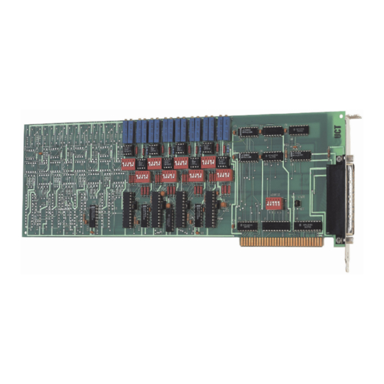
DAC's output is not updated until both bytes (first low byte, then high byte) are written. The CIO-DAC08-I and CIO-DAC16-I have a bank of nine address DIP switches. (See Figure 2-1.) There are no other switches or jumpers. 2 SOFTWARE INSTALLATION An installation program labeled InstaCal™... -
Page 6: Hardware Installation
Unless there is already a board in your system that uses address 300h (768 decimal), leave the switches as they are set at the factory. In the following examples, the board (CIO-DAC08-I or CIO-DAC16-I) are set for a base address of 300h (768 decimal). -
Page 7: Installing The Cio-Dac##-I In The Computer
Table 3-1. PC I/O Addresses FUNCTION FUNCTION RANGE RANGE 000-00F 8237 DMA #1 2C0-2CF 020-021 8259 PIC#1 2D0-2DF 040-043 8253 TIMER 2E0-2E7 GPIB (AT) 060-063 8255 PPI (XT) 2E8-2EF SERIAL PORT 060-064 8742 CONTROLLER (AT) 2F8-2FF SERIAL PORT 070-071 CMOS RAM & NMI MASK 300-30F PROTOTYPE CARD 080-08F... -
Page 8: Cabling To The Cio-Dac##-I
The CIO-DAC##-I connector is accessible through the PC/AT expansion bracket. The connector is a standard 37-pin D-type male connector. A mating female connector, such as the C37FF-2, is available from Measurement Computing. Several cabling and screw termination options are available from Measurement Computing. -
Page 9: Signal Connection- Current Loop
3.6 Signal Connection- Current Loop The basic CIO-DAC##-I current output circuit is shown in Figure 3-2. Loop power is from an external power supply. The supply voltage is from 6V to 36V, with 24V or 36V being typical choices. 4-20mA Control LLGND Figure 3-2. -
Page 10: Connector Diagram
C37FF-2, 2-foot cable with connectors. If frequent changes to signal connections or signal conditioning is required, refer to the information on the CIO-TERMINAL, CIO-SPADE50 and CIO-MINI37 screw terminal boards in the Measurement Computing catalog. -12V 19 GND 18 37 GND... -
Page 11: Register Architecture
4 REGISTER ARCHITECTURE The CIO-DAC##-I is a simple board to understand. All control and data is read/written with simple I/O read and write commands. No interrupt or DMA control software is required. Thus, the board's outputs are easy to control directly from BASIC, C or PASCAL. - Page 12 In summary form, the registers and their function are listed in the following table. Table 4-2. Register Map ADDRESS WRITE FUNCTION READ FUNCTION BASE + 0 D/A Least Significant Byte None BASE + 1 D/A Most Significant Nibble and None Channel address These two registers control all of the DACs on the CIO-DAC##-I.
- Page 13 After calculating the code required for the D/A data, combine it with the code required for the channel number. For example, to set the output on channel 3 to 11.890625mA: CODE = 11.890625mA - 4 / 16 * 4095 = 2020 The digital code for 2020 is 0111 1110 0100.
-
Page 14: Specifications
320 mA typical, 500 mA max +12V supply 150 mA typical, 190 mA max −12V supply 100 mA typical, 130 mA max CIO-DAC08-I +5V supply 320 mA typical, 500 mA max +12V supply 75 mA typical, 100 mA max −12V supply... - Page 15 EC Declaration of Conformity We, Measurement Computing Corp., declare under sole responsibility that the product: CIO-DAC16-I ISA-Type Current output card CIO-DAC08-I ISA-Type Current output card Part Number Description to which this declaration relates, meets the essential requirements, is in conformity...
- Page 16 Measurement Computing Corporation 16 Commerce Boulevard, Middleboro, MA 02346 (508) 946-5100 Fax: (508) 946-9500 Measurement Computing Corporation E-mail: info@measurementcomputing.com 10 Commerce Way Suite 1008 www. measurementcomputing.com Norton, Massachusetts 02766 (508) 946-5100 Fax: (508) 946-9500 E-mail: info@mccdaq.com www.mccdaq.com RegMapPC-CARD-DAC08.doc...


Need help?
Do you have a question about the CIO-DAC08-I and is the answer not in the manual?
Questions and answers