Table of Contents
Advertisement
Quick Links
Advertisement
Table of Contents

Subscribe to Our Youtube Channel
Related Manuals for Conel UR5i a


Summary of Contents for Conel UR5i a
- Page 1 UR5i a UR5i SL UMTS router USER’S GUIDE...
-
Page 2: Table Of Contents
OBSAH Contents Safety instruction Description of the router 2.1. Introduction 2.2. UMTS technology 2.3. HSxPA technology (High Speed Packet Access) 2.4. Delivery Identification 2.5. Antenna Connection 2.6. SIM Card Reader 2.7. Power Supply 2.8. Technical parameters 2.9. Description of the individual components of the router 2.9.1. - Page 3 CONTENTS 5.16. DynDNS Client Configuration 5.17. NTP Client Configuration 5.18. SNMP Configuration 5.19. SMS Configuration 5.20. External Port Configuration 5.21. USB Port Configuration 5.22. Startup Script 5.23. Automatic update configuration 5.24. Change password 5.25. Set real time clock 5.26. Set SMS service center address 5.27.
- Page 4 Information, notice – information, which contains useful advices or special interest. GPL licence Source codes under GPL licence are available free of charge by sending email on info@conel.cz. Conel s.r.o., Sokolska 71, 562 04 Usti nad Orlici, Czech Republic Issue in CZ, 7/30/2009 - 4 - 30.7.2009...
-
Page 5: Safety Instruction
SAFETY INSTRUCTION 1. Safety instruction Please, observe the following instructions: • The communication router must be used in compliance with all applicable international and national laws and in compliance with any special restrictions regulating the utilization of the communication router in prescribed applications and environments. •... -
Page 6: Description Of The Router
DESCRIPTION 2. Description of the router 2.1. Introduction The UMTS router is a compact electronic device based on the UMTS module which enables data transfers using UMTS/HSDPA/HSUPA/EDGE/GPRS/GSM technologies. Primarily, the router expands the capabilities of the UMTS module by the option of connecting more PC’s by means of the built-in Ethernet interface. -
Page 7: Hsxpa Technology (High Speed Packet Access)
DESCRIPTION 2.3. HSxPA technology (High Speed Packet Access) High Speed Download Packet Access and High Speed uploď Packet Access are an improved and extended version of the UMTS-TDD. HSDPA/HSUPA is available for both UMTS FDD and for UMTS TDD. HSDPA/HSUPA raises significantly bit rate for downlink. It is attained on the programmer level. -
Page 8: Antenna Connection
DESCRIPTION Basic delivered set of router includes: • UMTS router, • power supply, • crossover UTP cable, • external antenna, • plastic clips for the DIN rail with fixing screws, • installation CD containing instructions. In addition to the basics it is possible to deliver: •... -
Page 9: Sim Card Reader
DESCRIPTION 2.6. SIM Card Reader The SIM card readers for 3 V and 1.8 V SIM cards are located on the front panel of the router. To initiate the router into operation it is necessary to insert an activated SIM card with unblocked PIN in the reader. -
Page 10: Technical Parameters
DESCRIPTION 2.8. Technical parameters UMTS/HSDPA/HSUPA/EDGE/GPRS/GSM module Complies with standards EN 301 511, v9.0.2, EN 301 908-1&2, v3.2.1, ETSI EN 301 489-1 V1.8.1, EN 60950-1:06 ed.2 HSDPA parameters 3GPP rel. 5 standard bitrate 7,2 Mbps UE CAT. 1 to 6, 8, 12 HSDPA parameters 3GPP rel. -
Page 11: Description Of The Individual Components Of The Router
DESCRIPTION 2.9. Description of the individual components of the router 2.9.1. UMTS module The UMTS module is used for UMTS/HSDPA/HSUPA/EDGE/GPRS/GSM UMTS network wireless communication. It is integrated in the printed circuit board. The slide-out SIM card reader is accessible from the front panel. The FME antenna connector is accessible from the back panel. -
Page 12: User Interfaces (Connectors)
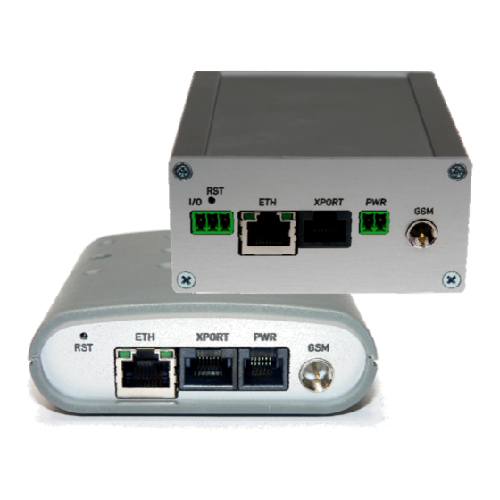
DESCRIPTION 2.10. User interfaces (Connectors) On the back panel of router the following connectors are located: • one RJ12 or MRT9 connector (PWR) – for connection of the power supply adapter, • one RJ45 connector (ETH) – for connection into the local equipment, •... - Page 13 DESCRIPTION Front panel UR5i SL Rear panel UR5i SL...
-
Page 14: Connection Of The Pwr Supply Connector
DESCRIPTION 2.10.1. Connection of the PWR Supply Connector Panel socket RJ12. Signal Description number mark Positive pole of DC supply voltage (+10 to +30 V) Signal not connected Signal not connected Positive pole of DC supply voltage (+10 to +30 V) Negative pole of DC supply voltage Negative pole of DC supply voltage Circuit example:... -
Page 15: Connection Of The Xport Connector - Rs232
DESCRIPTION 2.10.2. Connection of the XPORT Connector – RS232 Panel socket RJ45 (RS232 – DCE – Data Communication Equipment). Signal Description Data flow direction number mark Request To Send Input Clear To Send Output Data Terminal Ready Input Data Set Ready – connected to +4 V through Output 330 Ohm GROUND –... -
Page 16: Connection Of The Xport Connector - Rs485
DESCRIPTION 2.10.3. Connection of the XPORT Connector – RS485 Panel socket RJ45. Signal Description Data flow direction number mark Signal and supply ground Signal and supply ground TxRx- RS485 B (-) Input/Output TxRx+ RS485 A (+) Input/Output TxRx- RS485 B (-) Input/Output TxRx+ RS485 A (+) -
Page 17: Connection Of The Xport Connector - Rs422
DESCRIPTION At RS485 data cable more then 10m it is need to use overvoltage protection on the router side! 2.10.4. Connection of the XPORT Connector – RS422 Signal Description Data flow direction number mark SGND Signal and power supply ground SGND Signal and power supply ground RxD-... -
Page 18: Connection Of The Xport Connector - Mbus
DESCRIPTION Circuit example of the equipment with a router with data length more than 10 m: At RS422 data cable more then 10m it is need to use overvoltage protection on the router side! 2.10.5. Connection of the XPORT Connector – MBUS Panel socket RJ45. -
Page 19: Connection Of The Xport Connector - Cnt
DESCRIPTION Circuit example of the equipment with a router with data length more than 10 m: If an M-BUS data cable more then 10m it is need to use overvoltage protection on the router side! 2.10.6. Connection of the XPORT Connector – CNT Panel socket RJ45. - Page 20 DESCRIPTION Typical connection of the router measuring circuits:...
-
Page 21: Connection Of The Eth Connector
DESCRIPTION 2.10.7. Connection of the ETH Connector Panel socket RJ45. Signal mark Description Data flow direction number TXD+ Transmit Data – positive pole Input/Output TXD- Transmit Data – negative pole Input/Output RXD+ Receive Data – positive pole Input/Output RXD- Receive Data – negative pole Input/Output ATTENTION! Port ETH is not POE (Power Over Ethernet) compatible! The ETH router connection:... -
Page 22: Connection Of The Connector Usb
DESCRIPTION 2.10.9. Connection of the Connector USB Panel socket USB-A. Signal mark Description Data flow direction number Positive pole of 5V DC supply voltage USB data - USB data signal – negative pole Input/Output USB data + USB data signal – positive pole Input/Output Negative pole of DC supply voltage The USB router connection:... -
Page 23: Technical Specification Of I/O Port
DESCRIPTION 2.11. Technical specification of I/O port Port IO Environment Operating temperature -20 .. +55 °C Input/Output Binary input reed contact with trigger level 1,3 up to 1,4 V Binary output 120 mA/max. 30 V I/O port is part of the UR5i SL version only. 2.12. - Page 24 DESCRIPTION Jumper placement can be seen in the picture below (module Expansion port RS485/RS422 from TOP layer). We recommend that internal power supply is only chosen in the event that it is not possible to ensure external power supply. If internal power supply is chosen, converter RS485/RS422 is not galvanic separated.
-
Page 25: Modem Status Indication
DESCRIPTION • Expansion port CNT Expansion port CNT Power supply Internal …. Sleep 100 µA (counter is functional) Operation 2 mA Environment Operating temperature -20 .. +55 °C Storage temperature -20 .. +85 °C Standards Emission EN 55022/B Immunity ETS 300 342 Safety EN 60950 Isolation... -
Page 26: Putting Into Operation
DESCRIPTION 2.14. Putting into operation Before putting the UR5i or UR5i SL router into operation it is necessary to connect all components needed for the operation of your applications and the SIM card must be inserted (the modem is off). The modem is put into operation by connection of the power supply to the router. -
Page 27: Mechanical External Dimensions And Mounting Recommendations
DESCRIPTION 2.15. Mechanical external dimensions and mounting recommendations... - Page 28 DESCRIPTION For the majority of applications with a built-in router in a switch board it is possible to recognize two sorts of environments: • no public and industry environment of low voltage with high interference, • public environment of low voltage without high interference. For both of these environments it is possible to mount routers to switch board, the following it is not need have no examination immunity or issues in connection with EMC according to EN 60439-1 ed.2.
- Page 29 DESCRIPTION • sufficient space must be left before individual connectors for handling of cables, • for correct function of the router we recommend to use in switch - board earth- bonding distribution frame for grounding of power supply of router, data cables and antenna, •...
- Page 30 DESCRIPTION • the circuit diagram of the UR5i SL router is on the following pictures.
-
Page 31: Expansion Port Mounting
EXPANSION PORT MOUNTING 3. Expansion port mounting 3.1. Expansion port mounting for UR5i Attention! Expansion port XPORT include when the router UR5i is switch off. After unscrewed two screws (position 8) on box bottom part (position 3) and carried out box top part (position 2) the expansion port XPORT (position 6) connect to connector J3 (see below) of the router B-UR-5i motherboard (position 1) from TOP side. - Page 32 EXPANSION PORT MOUNTING Parts list and description Part Description Number UMTS router motherboard Box top part Box bottom part Rear head Front head Expansion port Distant columns for expansion port XPORT mounting to motherboard Screw for box completion...
-
Page 33: Expansion Port Mounting For Ur5I Sl
EXPANSION PORT MOUNTING 3.2. Expansion port mounting for UR5i SL Attention! Expansion port XPORT include when the router UR5i SL is switch off. After unscrewing four screws (position 10) on the rear panel (position 5) and removing it is possible to take out the B-UR-5i motherboard (position 1). The expansion port XPORT (position 2) is connected to connector J3 (see below) of the router B-UR-5 motherboard (position 1) from TOP side. - Page 34 EXPANSION PORT MOUNTING Parts list and description Part Description Number UMTS router motherboard Expansion port XPORT Left box part Right box part Rear head Front head Bottom box part Top box part Spacers for expansion port XPORT mounting to motherboard Screw for box completion...
-
Page 35: Change Of The Sim Cards
CONFIGURATION 4. Change of the SIM cards Attention! SIM cards include when the router is switch off. The SIM cards change on the front panel: Ensure that the router is disconnected from the power supply. Press the small yellow button next to the reader to eject the reader holder. Insert the SIM card into the reader holder and slide it in the reader. -
Page 36: Configuration Setting Over Web Browser
CONFIGURATION 5. Configuration setting over web browser Attention! If the SIM card is not inserted in the router, then it is impossible to operate. The inserted SIM card must have activated GPRS. Insert the SIM card when the router is switched-off. - Page 37 CONFIGURATION By each of the interfaces are then shown the following information: • HWaddr – hardware (unique) address of networks interface • inet – own IP address • P-t-P – IP address second ends connection • Bcast – broadcast address •...
-
Page 38: Dhcp Status
CONFIGURATION 5.2. DHCP Status Information about IP addresses, which was leased to the router by the DHCP server, is possible to find in menu in sum DHCP: • lease 192.168.1.2 (generally IP address) – assigned IP address • starts – information about time of assignation of IP address •... -
Page 39: Umts/Gprs Status
CONFIGURATION 5.4. UMTS/GPRS Status The item UMTS in the menu contains up-to-date information about PLMN (code of operator), cell, channel and signal quality of the selected cell, as well as neighboring hearing cells. The PPP Connection Log is in the bottom of this window where information about the make-up of the PPP connection is and pertinent problems on this formation. -
Page 40: Lan Configuration
CONFIGURATION 5.7. LAN Configuration To enter the network configuration, select the LAN menu item. In the first part of the window it is possible to define the network interface IP address (IP address), the network mask (Subnet Mask) and media type (Media Type), in the majority of cases set Auto- Negotiation. - Page 41 CONFIGURATION Example of the network interface with dynamic DHCP server: 192.168.1.2 GSM/GPRS 192.168.1.1 192.168.1.3 192.168.1.4...
- Page 42 CONFIGURATION Example of the network interface with dynamic and static DHCP server: 192.168.1.2 192.168.1.3 192.168.1.4 GSM/GPRS 192.168.1.1 192.168.1.10 01-23-45-67-89-ab 192.168.1.11 01-54-68-18-ba-7e...
-
Page 43: Vrrp Configuration
CONFIGURATION 5.8. VRRP Configuration To enter the VRRP configuration select the VRRP menu item. VRRP protocol (Virtual Router Redundancy Protocol) is a technique, by which it is possible to forward routing from main router to backup router in the case of the main router failure. If the Enable VRRP is checked, then it is possible to set the following parameters. -
Page 44: Umts/Gprs Configuration
CONFIGURATION Example of the VRRP protocol: Main router Virtual server ID 5 Host priority 255 APN 1 192.168.1.2 192.168.1.1 10.0.1.3 APN 2 Backup router 192.168.1.3 Virtual server ID 5 Host priority 100 5.9. UMTS/GPRS Configuration To enter the GPRS connection configuration select the GPRS menu item. If the Create GPRS connection option is selected, the router automatically tries to establish GPRS connection after switching-on. - Page 45 CONFIGURATION The choice Get DNS address from operator is given for easier configuration on client side. If this field is filled in, then the router tries to get an IP address of primary and secondary DNS server from the operator automatically. If the Check PPP connection option is selected, it has active control of connection over PPP.
- Page 46 CONFIGURATION Attention! We recommend checking the GPRS connection in case of uninterrupted running. The changes in settings will apply after pressing the Apply button. Annotation: • MTU (Maximum Transmission Unit) – it is the identifier of the maximum size of packet, which is possible to transfer in a given environment. •...
-
Page 47: Firewall Configuration
CONFIGURATION 5.10. Firewall Configuration By the help of a firewall it is possible to set IP addresses from which are possible to remotely access the router. The choice Allow remote access only from specified hosts is given for easier configuration of hosts. In this firewall configuration it is possible to set up to four remote accesses by the help of Source, Source IP Address, Protocol and Target Port. -
Page 48: Nat Configuration
CONFIGURATION 5.11. NAT Configuration To enter the Network Address Translation configuration, select the NAT menu item. By checking item setting Send all incoming packets to default server the Default Server item it is possible to put the router into the mode in which all incoming data from GPRS will be routed to the computer with the defined IP address. - Page 49 CONFIGURATION In these configurations it is important to have marked choice of Send all remaining incoming packets it default server, IP address in this case is the address of the device behind the router. Connected equipment behind the router must have set Default Gateway on the router.
-
Page 50: Openvpn Tunnel Configuration
CONFIGURATION In this configuration equipment wired behind the router defines the address Server IP Address. The router replies, while PING on address of SIM card. Access on web interface of the equipment behind the router is possible by the help of Port Forwarding, when behind IP address of SIM is indicating public port of equipment on which we want to come up. - Page 51 CONFIGURATION renegotiate period (reauthorization) of the OpenVPN tunnel. This parameter is possible to set only at username/password authentication or at X.509 certificate using. By parameter Max Fragment Size it is possible to define maximum sending packet size. Sending data is possible compress by lossless LZO compressions by parameter Compression, compression has to be on both tunnel ends.
-
Page 52: Ipsec Tunnel Configuration
CONFIGURATION Example of the OpenVPN tunnel configuration: 192.168.1.2 192.168.2.2 ppp0 10.0.0.2 192.168.2.0 tun 0 19.16.2.0 ppp0 10.0.0.1 192.168.1.0 tun0 19.16.1.0 192.168.1.3 OpenVPN tunnel 192.168.2.3 192.168.1.4 192.168.2.4 Default Gateway 192.168.1.1 Default Gateway 192.168.2.1 OpenVPN tunnel configuration: Protocol UDP Port 1194 1194 Remote IP Address: 10.0.0.2 10.0.0.1... - Page 53 CONFIGURATION In the IPsec Tunnel Configuration windows it is possible to define the tunnel name (Description), off - side tunnel IP address (Remote IP Address), identification of off-side tunnel (Remote ID), address nets behind off - side tunnel (Remote Subnet), mask nets behind off - side tunnel (Remote Subnet Mask), identification of local side (Local ID), local subnet address (Local Subnet), local network mask (Local Subnet Mask), sharable key for both parties tunnel (Pre shared Key), service life keys (Key Lifetime) and service life IKA SA...
-
Page 54: Gre Tunnels Configuration
CONFIGURATION Example of the IPSec Tunnel configuration: 192.168.1.2 192.168.2.2 ppp0 10.0.0.2 192.168.2.0 ppp0 10.0.0.1 192.168.1.0 192.168.1.3 IPSec tunel 192.168.2.3 192.168.1.4 192.168.2.4 Default Gateway 192.168.1.1 Default Gateway 192.168.2.1 IPsec tunnel configuration: Remote IP Address: 10.0.0.2 10.0.0.1 Remote Subnet: 192.168.2.0 192.168.1.0 Remote Subnet Mask: 255.255.255.0 255.255.255.0 Local Subnet:... - Page 55 CONFIGURATION The tunnels are active after entry of choice Create x GRE tunnel. In the singles window it is possible to define the IP address of the remote side of the tunnel (Remote External IP Address), internal IP address of the local side of the tunnel (Local Internal IP Address), internal IP address of the remote side of the tunnel (Remote Internal IP Address), address of the network behind the remote side of the tunnel (Remote Subnet) and the mask of the network behind the remote side of the tunnel (Remote Subnet Mask).
-
Page 56: L2Tp Configuration
CONFIGURATION 5.15. L2TP Configuration To enter the L2TP tunnels configuration, select the L2TP menu item. L2TP tunnel allows protected connection by password of two networks LAN to the one which it looks like one homogenous. The tunnels are active after enter of choice Create L2TP tunnel. In the window it is possible to define L2TP tunnel mode (Mode) on the router side, in case of client IP address of server (Server IP Address), start IP address in range, which is offered by server to clients (Client Start IP Address), end IP address in range, which is... -
Page 57: Dyndns Client Configuration
(Hostname), user name (Username) and password (Password). The changes in settings will apply after pressing the Apply button. Example of the DynDNS client configuration with domain conel.dyndns.org, username conel and password conel: If DNS servers are not assigned by the operator, then it is possible to configure it by inserting of script into start up window: echo “nameserver xxx.xxx.xxx.xxx“... -
Page 58: Ntp Client Configuration
CONFIGURATION 5.17. NTP Client Configuration NTP client Configuration can be called up by option NTP item in the menu. In the window can be defined the address prime (Primary NTP server Address) and secondary NTP server (Secondary NTP server Address), by the help of which the router, after first Example of NTP interface to the GPRS from make power supply, will adjust the inner clock. - Page 59 CONFIGURATION Every monitor value is uniquely identified by the help of number identifier OID - Object Identifier. OID is finished by „.9“. For the expansion port CNT the following range of OID is used: Description .1.3.6.1.4.1.30140.2.1.1.0 Analogy input AN1 (range 0-4095) .1.3.6.1.4.1.30140.2.1.2.0 Analogy input AN2 (range 0-4095) .1.3.6.1.4.1.30140.2.1.3.0...
-
Page 60: Sms Configuration
It is important to set the IP address of the SNMP agent (router) in field Remote SNMP agent. After enter the IP address is in a MIB tree part is possible show object identifier. The path to objects is: iso->org->dod->internet->private->enterprises->conel->protocols. 5.19. SMS Configuration... - Page 61 CONFIGURATION It is possible to send SMS in the form: Description go online sim 1 Switch to SIM1 card go online sim 2 Switch to SIM2 card go online Switch router in online mode go offline PPP connection termination set out=0 Set output on 0 on the Expansion port CNT set out=1 Set output on 1 on the Expansion port CNT...
- Page 62 CONFIGURATION After powering up the router, at introduction of the telephone number comes SMS in the form of: UR5i (Unit ID) has been powered up. PLMN:xxxxx,Cell:xxxx,Channel:xx,Level:-xxdBm. Where PLMN is – number of mobile operator, Cell – number of cell, Channel – used channel, Level –...
- Page 63 CONFIGURATION Example of the router onfiguration for SMS sending via serial interface: The SMS is possible to do for example in HyperTerminal program. After establishing connection with the router via serial interface or Ethernet, it is possible to do with SMS by the help of the next AT commands (more about AT commands see reference [1]): AT commands Description...
- Page 64 CONFIGURATION It is possible to find the new SMS by the help of command AT+CMGL=ALL. This command reproaches all SMS messages. Enter AT+CMGL=ALL +CMGL: <index>, <status>,<sender number>, ,<date>,<time> SMS text. +CMGL: 1,“REC UNREAD“,“+420721123456“, ,“08/02/02, 10:33:26+04“ Hello World! where <index> is ordinal number of the SMS, <status>...
-
Page 65: External Port Configuration
CONFIGURATION 5.20. External Port Configuration The expansion port configuration can be called up by airbrush option External Port in menu. Inside the window can be defined Baudrate, number of Data bits, Parity, number of Stop bits, Protocol and Mode. Split timeout is for messages. In mode TCP server it is necessary to enter the TCP port, on which the router will listen to incoming requests about TCP connection. -
Page 66: Usb Port Configuration
CONFIGURATION ppp0 10.0.0.2 RS232 ppp0 10.0.0.1 RS232 Settings in the router Settings in the router Mode: TCP server Mode: TCP client Server Address: - Server Address: 10.0.0.2 TCP Port: 2000 TCP Port: 2000 5.21. USB Port Configuration The USB port configuration can be called up by airbrush option USB Port in menu. Inside the window can be defined Baudrate, number of Data bits, Parity, number of Stop bits, Protocol and Mode. -
Page 67: Startup Script
CONFIGURATION Example of USB port configuration: Equipment ppp0 10.0.0.2 ppp0 10.0.0.1 192.168.1.1 192.168.1.100 Settings in application on PC: Settings in the router TCP connection on 10.0.0.2:2000 Mode: TCP server Server Address: - Default Gateway 192.168.1.1 TCP Port: 2000 Equipment ppp0 10.0.0.2 ppp0 10.0.0.1 Settings in the router Settings in the router... -
Page 68: Automatic Update Configuration
CONFIGURATION 5.23. Automatic update configuration In the window Automatic update it is possible to set automatic configuration update. This choice enables that router automatically downloads configuration and the newest firmware from the server itself. The configuration and firmware are stores on the server. -
Page 69: Set Sms Service Center Address
CONFIGURATION 5.26. Set SMS service center address In some cases it is need to set phone number of the SMS service centre because of SMS sending. This parameter can not be set when the SIM card has set phone number of the SMS service centre. -
Page 70: Backup Configuration
CONFIGURATION 5.29. Backup Configuration The router configuration is possible to save by help of the Backup Configuration menu item. After clicking on this menu it is possible to check a destination directory, where it will save the router configuration. 5.30. Restore Configuration In case it is needed to restore the router configuration, it is possible in Restore Configuration menu item to check configuration by help Browse button. -
Page 71: Default Settings
CONFIGURATION 5.33. Default settings LAN Configuration 5.33.1. VRRP Configuration 5.33.2. Firewall Configuration 5.33.3. -
Page 72: Nat Configuration
CONFIGURATION UMTS/GPRS Configuration 5.33.4. NAT Configuration 5.33.5. -
Page 73: Openvpn Tunnel Configuration
CONFIGURATION OpenVPN Tunnel Configuration 5.33.6. -
Page 74: Ipsec Tunnel Configuration
CONFIGURATION IPsec Tunnel Configuration 5.33.7. -
Page 75: L2Tp Tunnel Configuration
CONFIGURATION GRE Tunnels Configuration 5.33.8. L2TP Tunnel Configuration 5.33.9. DynDNS Configuration 5.33.10. NTP Configuration 5.33.11. -
Page 76: Snmp Configuration
CONFIGURATION SNMP Configuration 5.33.12. SMS Configuration 5.33.13. -
Page 77: Usb Port Configuration
CONFIGURATION Expansion Port Configuration 5.33.14. USB Port Configuration 5.33.15. -
Page 78: Startup Script
CONFIGURATION Startup script 5.33.16. Automatic update 5.33.17. -
Page 79: Configuration Setting Over Telnet
CONFIGURATION 6. Configuration setting over Telnet Attention! If the SIM card isn’t included in the router, it is impossible for the router to operate. The Included SIM card must be activated for GPRS transmissions. Insert the SIM card when the router is switched off. Monitoring of status, configuration and administration of the router can be performed by means of the Telnet interface. -
Page 80: Possible Problems
PROBLEMS, FAG AND KEEPING Possible problems Some network cards are able to be set in situation, when it is not possible to connect the router. It is possible to solve this problem in the following steps: hand by selection communication rates 10 MB/s in property network cards, connect router over switch, starts computer only after finalization start router. -
Page 81: Customers Support
During cleaning of the router do not use aggressive chemicals, solvents and abrasive cleaners! Conel Company hereby declares that the router narrated in this user’s guide fits all basic demands of directive 1999/5/EC (R&TTE). -
Page 82: Product Disposal Instructions
PROBLEMS, FAG AND KEEPING 11. Product disposal instructions The WEEE (Waste Electrical and Electronic Equipment: 2002/96/EC) directive has been introduced to ensure that electrical/electronic products are recycled using the best available recovery techniques to minimise the impact on the environment. This product contains high quality materials and components which can be recycled. -
Page 83: Guarantee Claim Guidelines
GUARANTEE 12. Guarantee Claim Guidelines Dear customer, The product that you have purchased was tested by the manufacturer and, before it was sold, the product’s functions were checked once more by our company’s technician. However if, in spite of the above-mentioned measures, a breakdown of this product occurs during the guarantee period, which makes proper utilization of the product impossible, we ask you to observe the Guarantee Claim Guidelines when asserting a guarantee claim. - Page 84 GUARANTEE hereupon onto the seller, and the ownership of the new product, onto the buyer. A new guarantee period starts running from the date of acceptance of the new product. In the event that the seller, upon agreement with the customer, has settled the guarantee claim by exchanging the object of the guarantee claim for a faultless product, the new guarantee of the product shall expire as follows: 1.
- Page 85 GUARANTEE Other guarantee claim conditions The fact that the object of the guarantee claim does not correspond to parameters that have been set for other similar types of products can not be considered to be a defect. For the assessment whether a defect has occurred, the product parameters included in the technical documentation of the product are decisive.
-
Page 86: Guarantee Certificate
GUARANTEE CERTIFICATE 13. Guarantee certificate Type of the device Serial number Guarantee period (in months) Seller Date of sale Stamp of the seller... - Page 87 GUARANTEE CERTIFICATE Date of reception of the guarantee claim by the seller Number of the guarantee claim report Date of reception of the device into the repair shop Date of completion of the repair by the repair shop Number of the receipt form of the repair shop Guarantee repair...
Need help?
Do you have a question about the UR5i a and is the answer not in the manual?
Questions and answers